G.R.A.S. 41AC-4 LEMO User manual

Instruction Manual
G.R.A.S. 41AC-4 LEMO Outdoor Microphone for
Community and Airport Noise (0 V pol.)
www.gras.dk
LI0171 – 18 February 2015

2LI0171 – 18 February 2015
Revision History
Revision Date Description
1 18 February 2015 First edition
Copyright Notice
© 2015 G.R.A.S. Sound & Vibration A/S
http://www.gras.dk
Any technical documentation that is made available by G.R.A.S. is the copyrighted work of
G.R.A.S. and is owned by G.R.A.S.
The content in this document is subject to change without notice. G.R.A.S. Sound & Vibration A/S
is not liable or responsible for any errors or inaccuracies that may appear in this document.
Trademarks
Any product names mentioned in this document may be trademarks or registered trademarks of
their respective companies and are hereby acknowledged.

3
LI0171 – 18 February 2015
Contents
Introduction.................................................................................. 4
Delivered Items............................................................................. 4
Installation .................................................................................. 6
System Integration ...................................................................... 12
Maintenance .............................................................................. 12
Accessories ................................................................................ 13
Specifications ............................................................................. 13
Calibration, Warranty and Service................................................... 17

4LI0171 – 18 February 2015
Introduction
The G.R.A.S. 41AC-4 Outdoor Microphone for Community & Airport Noise is a precision micro-
phone set (IEC 61672-1) for monitoring community noise and the noise of overhead aircraft.
It can be used for monitoring of noise with 90 degrees of incidence, typically community noise.
With the proper correction data, it can be used for 0 degrees of incidence, typically noise from
overhead aircraft. A USB flash drive with correction data is part of the delivery.
It is waterproof, rated at IP-55, and can operate unattended over a wide range of weather condi-
tions and temperatures for a very long period, i.e. a year or longer.
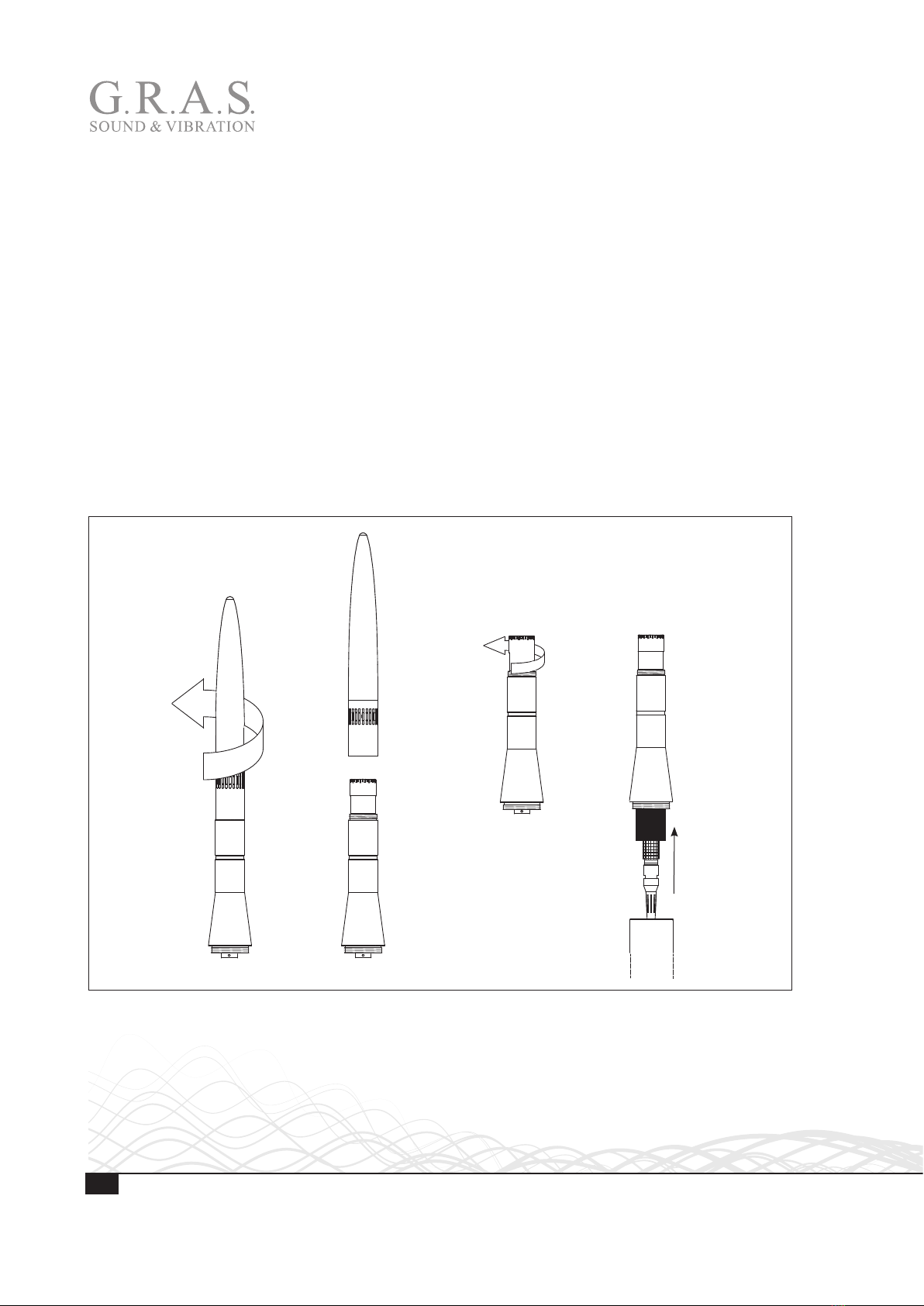
It uses a G.R.A.S. 40AE-S2 1/2” Prepolarized Free-field Microphone, High Sensitivity and a
G.R.A.S. 26AK 1/2’’ Standard Preamplifier with LEMO Connector. It is designed for use with a
Sound Level Meter with LEMO connector and power supply, and 0 V polarization voltage.
Important. The 40AE-S2 microphone and its protective grid have been modified for the 41AC-4.
Therefore, microphone and grid cannot be replaced by standard items.
Delivered Items
1/2" Prepolarized Free-Field Microphone, High Sensitivity 40AE-S2
1/2’’ Standard Preamplifier with Integrated LEMO Connector 26AK
O-ring for preamplifier OR2038
USB flash drive with correction data for 0° (resolution: 1/12 octave)
Wind Screen AM0378
Release Tube (for LEMO connector) GR1794
Top cone -
Upper housing -
Lower housing -
1” pole mount adapter RA0286
Tripod Adapter GR1096
Tripod thread adapter SK0017

5
LI0171 – 18 February 2015
41AC-4 is delivered pre-assembled except for the windscreen and thread adapter.
2-piece
1” pole mount
adapter RA0286
Lower housing
Windscreen
AM0378
Top cone
Preamplifier 26AK
Upper housing
½" microphone
40AE-S2
Release tube
GR1794
Tripod and thread
adapter SK0017
O-ring OR2038
Fig. 1. The parts of 42AC-4.

6LI0171 – 18 February 2015
Installation
Mounting 41AC-4 on Tripod or Pole Mount Adapter
The 41AC-4 is designed for permanent installation and therefore comes with an adapter for
mounting on a 1” pole. See Fig. 2 and Fig. 3, 3. The 41AC-4’s housing is attached to the mount-
ing fittings with a M18 x 1.5 thread.
Two-piece pipe adapter with
1” pipe thread (ISO 228/1-G1)
M18 x 1.5
GR1096 Tripod
thread adapter
with SK0017 1/4”
threaded bushing
Tripod thread adapter
with 3/8” thread (without
bushing)
Fig. 2. The 41AC-4 lower housing’s thread and adaptors for tripod and pole mounting.

7
LI0171 – 18 February 2015
Attaching the Lower Housing
1. Unscrew the upper part from the lower body.
2. Set the upper part aside and ensure that it is protected from dirt and moisture.
3. Slide the microphone cable through the adapter and through the lower housing, and screw the
housing onto the pole mount adapter.
4. Ensure that the lower housing is properly fastened to the pole mount adapter.
23
4
1
6
5
7
23
4
1
6
5
7
1 2 3 4
Fig. 3. Attaching the lower part of the housing to the pole mount adapter.

8LI0171 – 18 February 2015
Connecting the Cable to the Preamplifier
Important. Before connecting cable and preamplifier, you must ensure that the upper housing
can turn independently of microphone, preamplifier and cable. This is done by loosening the
microphone from the preamplifier by approximately half a turn.
Doing this ensures that the microphone-preamplifier and the preamplifier-cable connections are
not subjected to strain when the upper housing is screwed onto the lower housing. Also it makes
attachment of the cable to the preamplifier safe.
1. Unscrew the top cone.
2. Set it aside. Make sure it is protected from dirt and moisture.
3. Loosen the microphone housing by half a turn. Hold at the preamplifier connector and the
lower part of the microphone body while turning.
Important. Make sure to loosen the microphone housing and not only the protective grid!
4. Connect the cable to the preamplifier.
1 2 3 4
3
4
3
4
Fig. 4. Loosening the microphone-preamplfier: This must be done to avoid strain to the microphone-preamplifer assembly
when connecting the cable and mounting the upper part.

9
LI0171 – 18 February 2015
Mounting the Upper Housing and the Top Cone
When the microphone has been loosened from the preamplifier, you can safely mount the upper
housing onto the lower housing and subsequently mount the top cone.
1. Screw the upper part of the housing onto the lower part.
2. Fasten the microphone by turning it clockwise.
3. Screw on the top cone.
4. Ensure that the top cone is properly fastened.
1 2 3 4
6
5
6
5
Fig. 5. Mounting the upper housing and the top cone.

10 LI0171 – 18 February 2015
Mounting the Windscreen
The windscreen is lined with a plastic tube that ensures that it can be positioned correctly in
relation to the microphone’s diaphragm.
• When pushed down, the windscreen tube is prevented from going too far by the upper hous-
ing’s conical shape.
• When the windscreen is pushed as far down as it will go, it will be kept in place by a locking
groove. Because of this, it cannot be dislocated unintentionally, and incorrect measurements
due to an incorrectly positioned windscreen are avoided.
1. Slide the tube down over the top cone.
2. Ensure that the tube is pushed as far down as it will go.
1 2
End
stop
Locking
groove
Top of microphone
(diaphragm)
Fig. 6. Mounting the windscreen. When locked in the groove, the
center plane of the windscreen will be flush with the microphone diaphragm.
Table of contents
Other G.R.A.S. Microphone manuals


