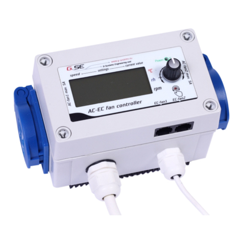
G-Systems 16A User manual

User manual 16Aventilation controller 16A
Version: 1:00:00
Date: 27/06/16
Approved for: All
Created by: G-Systems ngineering Ltd
Table of Contents
User manual 16Aventilation controller 16A ...........................................................................1
Introduction Foreword:.......................................................................................................2
Technical specifications:....................................................................................................2
Assembly:..........................................................................................................................2
Operation of the keypad: ..................................................................................................2
Description of the elements:..............................................................................................4
Menu structure:..................................................................................................................5
Function diagram:..............................................................................................................6
Menu functions:..................................................................................................................7
Main screen part 1.........................................................................................................7
Main screen part 2.........................................................................................................7
Main screen part 3.........................................................................................................7
Main menu:........................................................................................................................7
Submenu ventilator settings:.........................................................................................8
Settings of switched outputs XIT1: ...............................................................................10
Disabled:......................................................................................................................10
Output Sensor 1 heat:.................................................................................................10
Output sensor 1 cool:...................................................................................................11
Output sensor 1 humidify/moisturise:..........................................................................11
Output sensor 1 dehumidify/drying; Output sensor 2 heat; Output sensor 2 cool:.....11
Output 1 timer:.............................................................................................................11
Settings of switched outputs XIT2:................................................................................12
Submenu general settings:..............................................................................................12
Time and date settings:...............................................................................................12
Language settings:......................................................................................................13
Light sensor settings:...................................................................................................13
LCD Display settings:..................................................................................................13
Alarm settings:.............................................................................................................13
Recording of historical data (Only for model with USB recording):.............................14
Reset to factory settings:.............................................................................................14
page 1 of 15

Introduction Foreword:
Thank you that you have chosen the G-Systems ngineering Ltd 16A fan controller
product.
The 16A fan controller is a climate controller which can measure the air temperature
humidity and water temperature. The controller integrates several measurements
simultaneously and continuously controls devices such as intake- and exhaust fans and 2
switched channels can be individually and user definied programmed on / off. The 16A fan
controller controls based on the measurement data all functions, depending on the model
saves all setpoints and actual values to an external USB memory stick in a .csv format
(comma-separated values). These values can be evaluated on a computer at a later time,
or with the free of charge GS Growthanalizer software.
Technical specifications:
Operating voltage: 230V / 50Hz
Depending on the country the maximum power rating of the power-cord is variable:
VD L typ max: 16A, Schuko
VD F type max: 16A, France
VD type max:13A, Switzerland
VD U type max 13A, ngland
Loading of the individual outputs:
Intake fan max: 10A 2300W cos 1
xhaust fan max : 10A 2300W cos 1
xit 1 max: 10A 2300W cos 1
xit 2 max: 10A 2300W cos 1
The sum of all the currents can not exceed prescribed maximum current of the country
socket!
Assembly:
Mount the 16A fan controller with the included mounting bracket to a non-flammable
surface such as brick concrete and never on wood, plastic carboard, etc. Make sure that
on your choice of the place have sufficient ventilation in the location and the heat can be
dissipated. Avoid small unventilated rooms or cabinets. Improper installation will result a
overheating of the controller!
Operation of the keypad:
The controller is operated by four menu keys.
With the arrow keys UP and DOWN the various menu lines can be selected. Press
page 2 of 15

NT R to go one level deeper into the submenu and SAV / XIT one level back.
If settings get changed with the two arrow keys you don't have to confirm with NT R, the
values get stored with SAV / XIT
! All values get stored in an internal memory and are also after a power failure or
prolonged disconnection available. Time and date have a back-up capacitor which runns
about 72 hours. After this time they have to be setted again.
page 3 of 15

Description of the elements:
1. Connection for exhaust fan
2. Connection for intake air fan
3. Programmable exit 1
4. Programmable exit 2
5. Temperature L D
6. xit 1 L D
7. Humidity L D
8. Day / night L D
9. Alarm L D
10. xit 2 L D
11. UP arrow
12. DOWN arrow
13. SAV / XIT
14. NT R
15. Powersupply
16. Sensor cable for temperature and humidity (only gases)
17. Sensor cable for temperature (liquids and gases)
18 LCD display with 2x16 characters
19 USB L D
20. USB port
page 4 of 15

Menu structure:
page 5 of 15

Function diagram:
page 6 of 15

Menu functions:
Navigate the main menu with the UP / DOWN buttons.
Main screen part 1
Temperature T1 ° C Shows the measured in ambient air temperature.
Humidity in RH Shows the measured in the room relative humidity.
Temepratur T2 in C ° Displays measured in the water temperature.
Time Displays the current time in hours and minutes.
Main screen part 2
Fanspeed 1 shows in% the fan speed of the exhaust air fan.
Fanspeed 2 shows in% the fan speed from the supply air fan.
Main screen part 3
Alarms of the exceeded maximum values.
T1 = Temperature sensor 1 max.
RH = Humidity sensor 1 max.
T2 = Temperature sensor 2 max.
Alarms of underrun minimum values.
T1 = Temperature sensor 1 min.
RH = Humidity sensor 1 min.
T1 = Temperature sensor 2 min.
Confirm with the SAV / XIT button an alarm. The 9. alarm L D will switch off should the
actual value be below the set value. Depending on the model there is located a dry contact
in the inside the 16A controller. This contact is closed on alarm.
Main menu:
Go with the NT R button one level deeper into the menu. Here is a selection of the four
main menu items.
1. Set fan settings = Ventilator settings
2. Set exit 1 = Output setting of exit 1
3. Set exit 2 = Output setting of exit 2
4. General settings = General Settings
page 7 of 15
Mainscreen 1
T1=23.4C° RH=60%
T2=19.1C° 09:13
Fanspeed 1 90%
T1--- T2--- H---
Fanspeed 2 70%
T1--- T2--- H---

Scroll with the UP / DOWN keys to receive the downward hiden records.
The function to select is displayed flashing. Press the NT R key to select and to get into
the submenu.
Submenu ventilator settings:
Here you find all settings for both fans-outputs " xhaust fan" and "Intake fan" exhaust fan
on the left and right supply air fan. On AC fans can be loaded max 2200W per output,
depending on the country and plug type, but you can connect a maximum of 3600W total
load. Depending on model you have, there are in the inside of the 16A controller 2 outputs
for C-fan 0-10V and PWM signal paralel connected to the AC socket.
1. Set temperature = Temperature setting
2. Set humidity = Humidity setting
3. Fan settings = Ventilator Setting
Scroll with the UP / DOWN keys to display the below information.
1. Fan day = Ventilation day
2. Fan night = Ventilation night
3. Hysteresis = hysteresis
What is hysteresis? Hysteresis refers to the value between the lowest and the highest
value of the controlling range.
xample: We set the temperature to 25°C with a hysteresis of 2°C. The fan starts from
25°C to controll and reaches the maximum speed + 2°C hysteresis at 27°C. In this 2°C
hysteresis of 25°C to 27°C, the fan speed changes linearly according the temperature
difference.
The function to select is displayed flashing. Press the NT R key to select them.
page 8 of 15
Set fan settings
Set e it 1
Set e it 2
Generl settings
Set temperature
Set humidity
Fan settings

Select the desired setting, which you like to change, e.g. "Vent. Day. " Now, the value
starts flashing which can be changed with the UP DOWN buttons. Press once to change
by 0.1 or hold the button to change the value fast. If you have set the desired value, save
the new setting with the SAV / XIT button.
Repeat this procedure to change all other values in the menu.
With the SAV / XIT button to return back to the sub menu fan settings. Repeat this
procedure for the humidity setting. The third setting you can find the fan settings. Under
this sub menu, you get the following settings:
1. Minimum speed = Minimum speed setting (exhaust fan)
2. Maximum speed = Maximum speed setting (exhaust fan)
3. Negativepressure = Negative pressure setting (intake air fan)
Here you can set the minimum and maximum speed of the exhaust fan. These values will
never be exceeded in day and night mode and are always the same. The supply air fan
don't have a minimum speed value and will turn off when the temperature and humidity
undercuts the set value. By setting of the minimum speed value at the exhaust fan you
avoid odours escape through small openings in the room. By setting the maximum speed
value you avoid the fans making to much noise on full load. The third setting you have the
negative pressure, this setting reduces the intake fan speed according the value of the
exhaust fan speed and work synchrony together. For example: If we set a -20% negative
pressure, the exhaust air fan operates at full load 100%, the intake fan will have 80%. The
xhaust fan removes more air from the room as the intake fan blows inside and you obtain
a guaranteed negative pressure during the regulation. If the exhaust fan runs at 50% then
the intake air fan runs at 40%. -20% of its power. You can see this current ratio in the main
page 9 of 15
Fan day 22.8C°
Fan night 20.3C°
Hysteresis 2.5C°
Sub menu fan setting
Set temperature
Set humidity
Fan settings
Fan settings
Minimum speed
Ma imum speed
Negativepressure
Fan1 10%
Fan1 100%
Fan2 -50%

screen part 2.
Settings of switched outputs XIT1:
In the main menu you find “Set exit 1” = Settings output exit 1. Push the NT R button to
get one level deeper into the menu. Than push again to “choose function”. The following
functions are available:
x = disabled = Output disabled
x = T1 heat = Output sensor 1 heat
x = T1 cool = Output sensor 1 cool
x = Rh humidify = Output sensor 1 humidify/moisturise
x = Rh dehumidi = Output sensor 1 dehumidify/drying
x = T2 heat = Output sensor 2 heat
x = T2 cool = Output sensor 2 cool
x = timer = Output timer
Scroll with UP / DOWN buttons to the desired function and confirm with NT R. If a
function has already been selected, you can use "set value" to change the values. If you
like to switch to another function, select the new function in"Set exit 1". Change the values
or confirm the new function with the SAV / XIT button.
Disabled:
This function turns off the output.
utput Sensor 1 heat:
This function is measuring the air temperature and can be to connected a heater. In the
submenu you can make the following settings:
page 10 of 15
Choose function
E 1= S1 heat
E 1= S1 cool
E 1= S2 humidify
E 1= S2 dehumidi
E 1= S3 heat
E 1= S3 cool
E 1= timer
E 1= disabled
E it 1 Sensor 1
Heat day 24.0C°
Heatnight 24.0C°
Hyst. -02.0C°

Heat day = Heater temperature by day time
Heatnight = Heater temperature by night time
Hyst. = Hysteresis setting
Select e.g: "Heat day" here you can adjust the temperature on the day time. Proceed as
usual, pressing NT R the value starts to blink, change the value with UP / DOWN
buttons, you can store the value with SAV / XIT. Go to the next setting "Heatnight" and
repeat the procedure.
The hysteresis determines the quiescent condition of the contact. e.g: If the hysteresis is
set to -2.0°C and a set value to 24.0°C, then the heater will at 24.0°C - 2.0°C = 22.0°C and
among switch on and reaching the value of 24.0°C switch off again. This contact will
remain off until the value again drops below 22.0°C.
utput sensor 1 cool:
The procedure is the same as in "Output Sensor 1 heat" only the hysteresis works in
reverse mode during the cooling. e.g: If the hysteresis is set to + 2.0°C and a set value is
24.0°C, the cooling capacity becomes 24.0°C + 2.0°C = 26.0°C and by reaching 24.0 °C is
off again. This contact will remain off until the value rises above 26.0°C.
utput sensor 1 humidify/moisturise:
The procedure is the same as before. When connecting a humidifier, choose the relative
humidity = rH in % at day and at night time and set the desired hysteresis.
utput sensor 1 dehumidify/drying; utput sensor 2 heat; utput
sensor 2 cool:
The procedure is repeated for all other outputs as previously.
utput 1 timer:
If you choose the timer function it allows you to enter the start and end time in 24 day
cycles. Start time in hours and minutes, end time in hours, minutes and seconds. There
are 25 cycles per output programmable.
Select the " x = timer" xit 1 timer 1. The first five character 00:00 represents the on-time
in hours and minutes from 00:00 to 23:59. The next eight character 00:00:00 stand for off-
time in hours, minutes and seconds from 00:00:00 to 23:59:59 in 24hour format.
page 11 of 15
E it 1 timer 01
E it 1 timer 02
E it 1 timer 03
00:00 00:00:00
00:00 00:00:00
end disabled
h h : m m h h : m m : s s

Press NT R button, the first two character of the switch on time starts to blink. Now you
select the hours for the on-time. Change the value with UP / DOWN buttons and confirm
with NT R. Now the next two minutes-character of the on time starts to blink. Repeat the
process, and confirm with NT R. Now blinks the hours of the off time, repeat the process
and set the minutes and seconds of the off time. Save the first program step with SAV /
XIT. With the DOWN button to enter the next programming step, it shows on the display
xit 1 timer 02 for the second programming step. Repeat everything again until you reach
the next programming step xit 1 timer 03. When you are finished, press the SAV / XIT
button to save and return to reach the selection menu "Set xit 1"
To delete a program step, set the time back to 00:00 00:00:00.
When you have finished programming the " xit 1" press SAV / XIT to return to the main
menu.
Settings of switched outputs XIT2:
Select "Output 2" and repeat the same procedure as described for "Output 1"
Submenu general settings:
Navigate in the main menu to "General settings.", press NT R to get the selection.
Select one of the following settings that you want to change.
Here can be made all the general settings for the 16A fan controller:
Set date / time = Time and date settings
Set language = Language settings
Set photosensor = Light sensor settings
Set display = LCD Display settings
Set alarm = Alarm settings
Set log file = Recording of historical data (Only for model with USB recording)
Res. factory set = Reset to factory settings
page 12 of 15
Set time
Set language
Set photosensor
Set display
Set alarm
Set log file
Res. factory set

Time and date settings:
Press NT R to set date and time in the sub menu "Set date / time". As first you have to
set the date in the format day, month, year. After this set the time in hours and minutes.
The first day field starts to blink, now you can set the day with the buttons UP / DOWN.
Press NT R to confirm and move to the next months field. Repeat the procedure and
make set the year. Press NT R again and set the hours field, repeat the procedure for
the minutes. Save the settings you have made with SAV / XIT and return to the
selection menu "General settings."
Language settings:
Go to the menu "Language Settings.Press NT R to set Languages in the sub menu "Set
language" The preferred language starts blinking. Select with the UP / DOWN buttons the
desired language, confirm with SAV / XIT. The new language is activated now.
Light sensor settings:
Go to the menu "Set photosensor". This is used for day> night or night> day change over.
Depending on the state day or night, the controller selects the appropriate settings you
have set previously in the controller. Here you will see the current value of the light sensor,
this occurs in daytime almost 100%. As darker it is, as lower is this value. Set the switching
threshold. press again NT R the value begins to blink, change the value with UP /
DOWN buttons and save with SAV / XIT to return to the light sensor menu. Now select
the "Switch time". The switching time is a time delay which starts a count down after
reaching the light sensor level. During this time the switching threshold remains. Only after
expiration of the delay time, the controller will perform the switching threshold. If this time
gets interrupted, the time delay starts to count down again from beginning. This function is
used to prevent an immediate change over e.g: A door gets opened briefly. Press NT R,
the value starts to blink, change the value with UP / DOWN save it with SAV / XIT.
LCD Display settings:
Go to the sub menu “Set display” this is used to change the state of the LCD back light.
You have the choice of Automatic, on or off. Change the value with UP / DOWN buttons
and save it with SAV / XIT.
Alarm settings:
Here you can set the maximal and minimal alarm values of the sensors. In case of an over
page 13 of 15
Photosensor 35%
Switch at: 50%
switch time 300s
LCD back light
automatic
on
off

or under cut of the set value you will receive an alarm message on the 9. Alarm L D on
the foil. Depending on the model you have there is a free contact in the inside of the
controller which is closed by alarm. You can read the alarm in the main screen part 3 and
confirm it with SAV / XIT button. Should the measured value still exceed the set alarm
value than the alarm get immediately activated again.
Go to the menu “Set alarm”. Choose the sensor and confirm with NT R, choose now the
alarm value with UP / DOWN buttons. Push the NT R button to change the value with
UP / DOWN buttons, save it with SAV / XIT button. Repeat this this procedure to
change all the other alarm values.
Recording of historical data ( nly for model with USB recording):
Depending on the model you have, Recording of historical data is only for controllers with
USB connection.
Go to the menu “Set log file” under the sub menu “Rating” you can choose the Repetition
rate e.g: 5minutes. The controller will save all the data's every 5minutes to your USB
memory stick. Push NT R button the value begins to blink, change the value with the UP
/ DOWN buttons, save it with SAV / XIT.
General limitations:
All firmware versions support BOMS devices formatted in FAT12, FAT16 or FAT32 file
systems only where the sector size is 512 bytes. No other file systems or sector sizes are
allowed.
Format only the USB memory stick on your computer (Windows 7, 8, 10) Plug the USB
memory stick into the USB socket on the controller. If you have set the memory frequency
to 5minutes so every 5minutes once will be written the current measurement data and
settings to the USB memory stick. Make sure when unplugging the USB memory stick
from the controller he is not saving the data's in this moment. Should this happens the file
can be damaged or even freeze the controller. A restart of the controller is required. Plug
the power cord for about 20 seconds from the mains.
Reset to factory settings:
Go to the sub menu "Res. factory set" change with UP / DOWN buttons from No? to Yes?
page 14 of 15
Ma .temp. 32.3C°
Ma .temp. 32.3C°
Min.temp.-12.6C°
Min.temp.-12.6C°
Sensor T1 temperature
Sensor T2 temperature
Ma .humidity 60%
Min.humidity 10%
Sensor Rh humidity

Confirm with NT R. The controller reset all the data back to the original factory settings
except time and date settings.
page 15 of 15
Table of contents
Other G-Systems Controllers manuals