G2 LHD-INT User manual

LHD-INT & LHD-EOL
Digital Linear Heat Cable Interface
Installation Guide
Introduction
This guide gives an overview of the installation of the digital linear heat cable interface and end of
line unit. There are 2 distinct parts; LHD-I T and LHD-EOL but they operate as a pair. The units
are a universal unit and should operate with most digital linear heat cables available on the market.
However we supply and have tested these units exclusively with the LHDC supplied by PATOL.
The purpose of the 2 units is to act as an interface between the fire control equipment and the digital
linear heat cable. This allows for a flexible cable to be routed to the initial position of the digital
linear heat cable and then for end to end monitoring and testing between the LHD-I T and LHD-
EOL. At the I T position the status of the cable can be seen by the 3 LED status indicators and by
pressing the two buttons on the EOL unit a fault and fire condition can be simulated without the
need to open either terminating enclosure.
LHD-INT & LHD-EOL Installation Guide Page 1 Rev.1.7 ©G2 ecurity Pty Ltd

General Specification
The general parameters of LHD-I T and LHD-EOL can be found in table 1 and table 2
respectively.
Model LHD-I T
Operating Voltage 24Vdc
Voltage Range 16Vdc to 28Vdc
Current Standby <20mA
Current Fire
Condition <30mA
Current Fault
Condition <25mA
Operating
Environment Temp -55oC to 60oC
Operating
Environment
Relative Humidity
95%
Protection class IP66
Dimensions Enc. 90mm x 85mm x 52mm
Overall Dimensions 130mm x 85mm x 52mm
Table 1 – General pecification LHD-INT
Model LHD-EOL
Operating Voltage o Active Elecronics
Operating
Environment Temp -55oC to 60oC
Operating
Environment
Relative Humidity
95%
Protection class IP66
Dimensions Enc. 90mm x 85mm x 52mm
Overall Dimensions 130mm x 85mm x 52mm
Table 2 – General pecification LHD-EOL
LHD-INT & LHD-EOL Installation Guide Page 2 Rev.1.7 ©G2 ecurity Pty Ltd
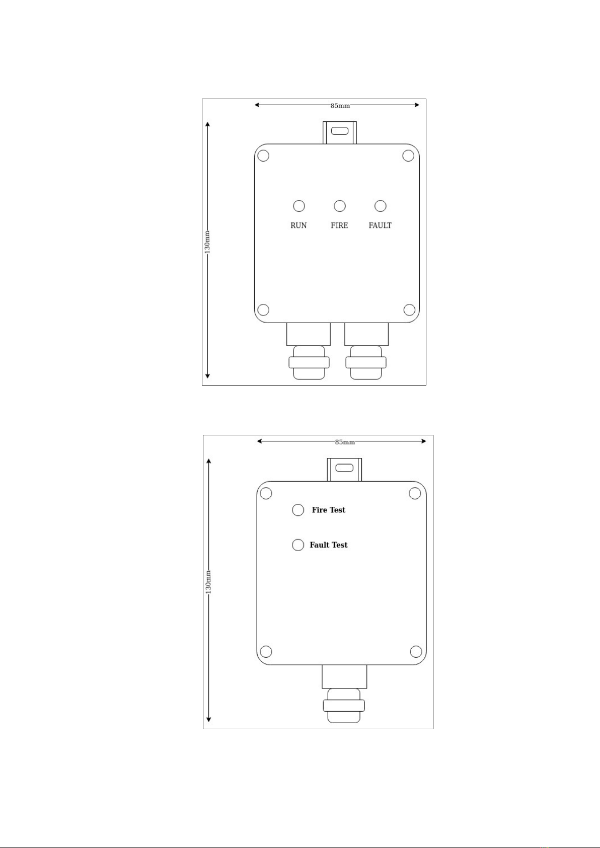
Physical Characteristics
Diagram 1 – Physical Layout LHD-INT
Diagram 2 – Physical Layout LHD-EOL
LHD-INT & LHD-EOL Installation Guide Page 3 Rev.1.7 ©G2 ecurity Pty Ltd
Installation
The devices are attached to a suitable structure by use of the top anchor point. This allows for firm
connection without compromising the weatherproofing of the enclosure.
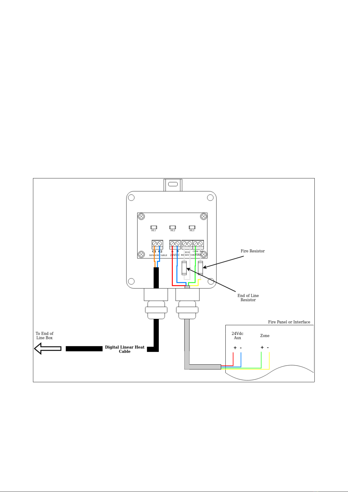
The LHD-I T unit has two cable glands, the left hand gland facilitates the entry of the digital linear
heat cable so that it can be terminated in the LHD-I T as shown in diagram 3. The right hand cable
gland allows for a 4 core cable to enter the LHD-I T unit to terminate the 24Vdc power and the
zone interface. The LHD-I T can be connected directly to a conventional fire panel zone and
auxiliary power output or to an input interface from an addressable fire detection panel.
The termination into the I T-EOL is simply one core of the digital linear heat cable into each
terminal, there is no need to observe any polarity.
PLEASE OTE neither the LHD_I T OR LHD_EOL will operate correctly without both being
installed on the digital linear heat cable.
Diagram 3 – LHD-INT Cable termination
Fire and EOL resistors are dependent on the fire alarm control equipment specification.
LHD-INT & LHD-EOL Installation Guide Page 4 Rev.1.7 ©G2 ecurity Pty Ltd

LHD-EOL Operation
Pressing the Fire Test button (diagram 4) results in placing a simulated fire condition on the digital
linear heat cable. The corresponding LHD-I T should indicate a fire condition as detailed in the
follow section of this document. In addition any connected fire alarm equipment should also signal
a fire condition.
Pressing the Fault Test button (diagram 4) results in placing a simulated fault on the digital linear
heat cable. The corresponding LHD-I T should indicate a fault condition as detailed in the follow
section of this document. In addition any connected fire alarm equipment should also signal a fault
condition.
Diagram 4 – LHD-EOL operation
LHD-INT & LHD-EOL Installation Guide Page 5 Rev.1.7 ©G2 ecurity Pty Ltd
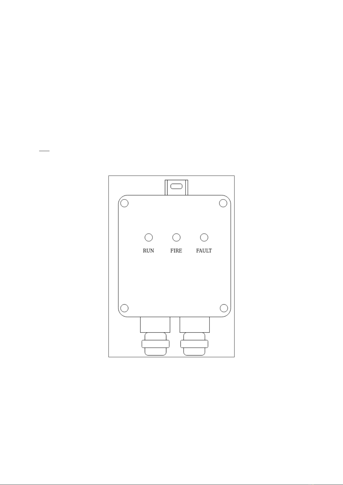
LHD-INT Operation
The LHD-I T comes with 3 external LED indicators;
RU – This is illuminated at all times showing that the unit has voltage applied and is powered on.
FIRE – This LED is only illuminated in the event of a fire condition, or simulated fire condition
from EOL testing. It will also indicate that it has triggered the fire event through to the fire control
equipment
FAULT – This LED is only illuminated in the event of a fault condition, or simulated fault condition
from EOL testing. It will also indicate that it has triggered the fault event through to the fire control
equipment
If NO LED indicates are lit then the LHD-I T is not operational.
Diagram 5 – LHD-INT operation
LHD-INT & LHD-EOL Installation Guide Page 6 Rev.1.7 ©G2 ecurity Pty Ltd

aintenance
The device should be inspected and cleaned on a schedule determined on site based on the
environment that the device has been fitted.
The testing of the device should be done in accordance with the site schedule and in-line with local
installation fire detection codes of practice. Testing is simply achieved by carrying out the
operational steps as detailed in the above sections of this manual.
If the device does not perform as expected then both the LHD-I T and LHD-EOL units should be
opened and cable terminations be inspected.
Should these appear to be fault free then the digital linear heat cable should be removed from the
termination and tested with a multi-meter.
If this proves to provide unsatisfactory results then the digital linear heat cable will need to be
inspected to ascertain where the physical fault has occurred.
If the digital linear heat cable is performing correctly yet the LHD-I T and LHD-EOL are not
performing as expected, then either the 24Vdc powers supply is not working or the unit themselves
are faulty. There are no serviceable parts within either unit so exchange for know working units and
repeat maintenance testing.
LHD-INT & LHD-EOL Installation Guide Page 7 Rev.1.7 ©G2 ecurity Pty Ltd
This manual suits for next models
1
Table of contents


