G3LIV ISOTERM-MULTIMODE User manual

ISOTERM-MULTIMODE
INSTRUCTIONS for
DATA-CW-FSK-INTERFACE
de G3LIV
July 2012 Series 5

Welcome to the World of DATA.
ISOTERM-MULTIMODE
The ISOTERM MULTIMODE as its name implies is designed to be used with AFSK DATA/CW/FSK
andbeing fully isolated it reduces the chance of RF and Earth type feedback problems. Which can result in
unacceptable signals being radiated. There are no physical connections between the Computer and Rig
grounds. This helps reduce any possible earth loop problems.
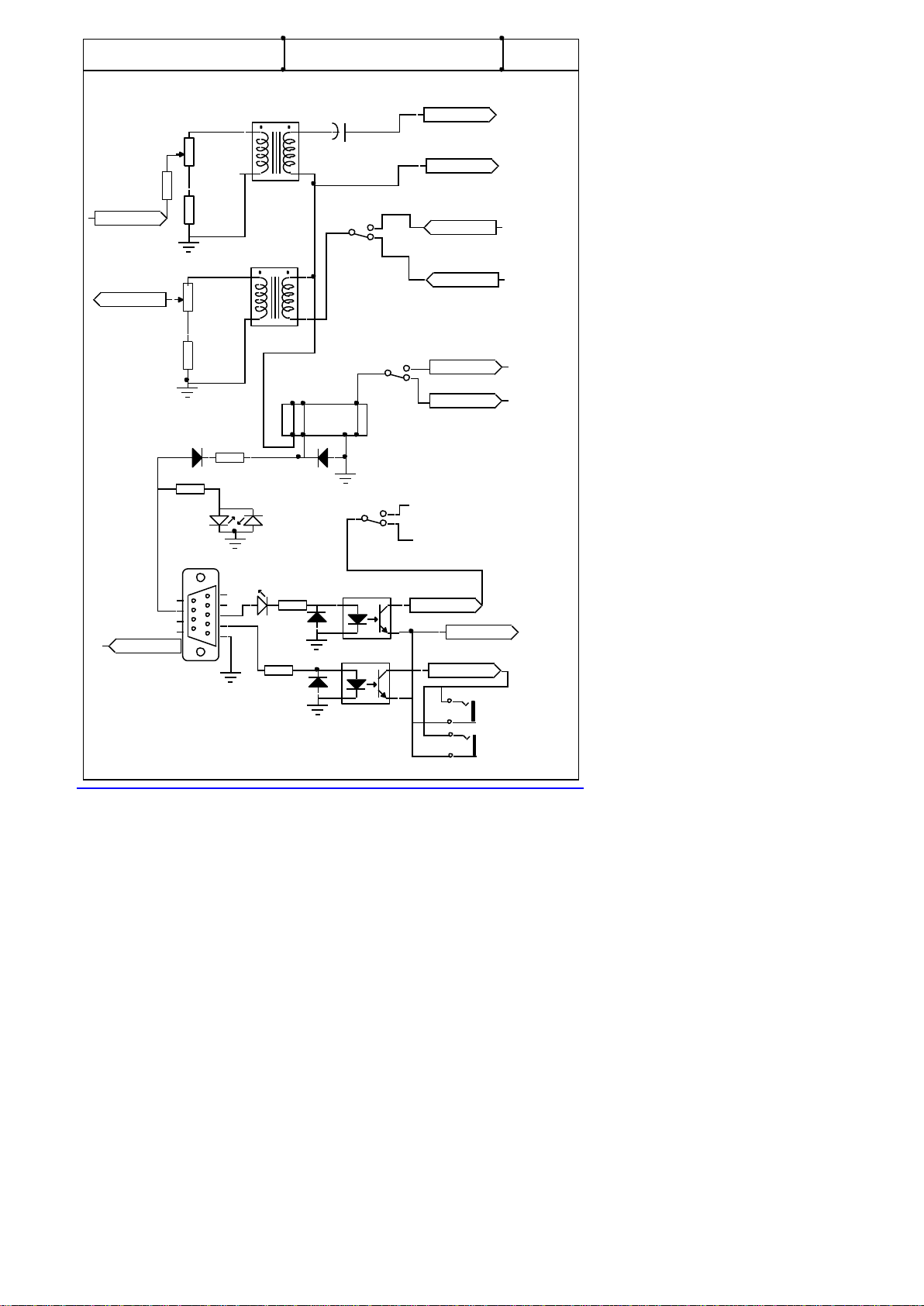
Both Audio paths between the Computer and Rig are Transformer coupled, whilst the PTT is coupled
through a Miniture DIL Relay and both the CW and FSK isolated through Opto Isolators.
ALL leads in and out of the ISOTERMs are screened, however it is still good practice to keep leads as
short as possible. Good practice like keeping leads apart from antenna and other computer I/0 cables can
only help in obtaining a good clean signal on the bands.
I won’t go into setting up the transmitter parameters as these are well covered in the HELP FILES on the
popular software programmes. Including the supplied ones. But you must make sure that you go to SET
UP and designate COM's port and sample rate ,enter 11025 to start with if you are requested. PRINT
OUT THE HELP FILES ON THE SOFTWARE YOU DECIDE TO USE and READ them.
You will on inspection of the MULTIMODE interface see that there are 2 cables coming out from the rear.
One has 2-3.5mm Jack Plugs on a 2 core screened cable. One with a marker band on it.
This should be inserted into LINE IN on the SOUNDBOARD or Mike if using a laptop.
It carries the AUDIO from your RX through the MULTIMODE to the Soundboard to drive theWaterfall.
The other 3.5mm Jack should be inserted into LINE OUT on the SOUNDBOARD or HEADPHONEs if
using a Laptop. This carries the AUDIO OUTPUT of the SOUNDBOARD through the MULTIMODE to
the rigs Mike or alternative mike inputs on rear of rig. The Rig cable is a replaceable one so as to give
choice of rig type used. Many transceivers can be catered for from the AFSK output of the 6 Pin Mini Din
socket.
The front panel of the Multimode is fitted with 2 attenuators . The RIGHT side of the pair with GREEN
control will reduce the drive voltage from the Rigs AUDIO OUTPUT into the Soundboards LINE IN, and
used in conjunction with the SOUNDBOARDs LINE IN slider, will allow correct level of drive to be
presented to the WATERFALL for best Waterfall apperance. This control should be set to MID position
when setting up the LINE In slider on the Soundboards control panel.. The LEFT control with a RED
conrol will reduce the drive from the soundboards Line Out and should be set to suit your individual TX
drive requitements. Again it is a good idea to set this at MID position when setting up the Soundboards
control panel. Standard 100 watt SSB rigs should not be driven harder than 50 watts. 30 to 40 watts is
adequate for DATA transmissions.
The other lead has a 9 pin D connector fitted. This should be inserted in COM's port you have selected in
the software, this 9 pin D lead carries CW/FSK/PTT inputs. The interface is wired for RTS when PTT is
set up.
I have enclosed a CD with various popular programs, Please use DIGIPAN at first. I am more experianced
in this program and more able to help you should you have problems at first setting up.
DIGIPAN has not been updated for VISTA or Win7. I therefor recommend AIRLINK EXPRESS.
I am not allowed to add this to my CD .The writer would not give me permission, so it needs tro be
downloaded from the Web.
Page 1… ISOTERM MULTIMODE Feb 2010. Series 5

On the soundcards control panel, The VOLUME and WAVE sliders controls the amount of audio
being fed to the Rig Via the Multimodes RED attenuator And the Line IN or MIKE sliders the
amount of Receiver Audio driving the Soundboard input. A little play with these controls will make
there function obvious.
All my interfaces can of course be used with most Soundboard Data programmes.
Further along the rear panel from the 2 screened cables. Is a 6 Pin mini din socket, this carries AFSK Data
signals from and to the selected transceiver. This cable is supplied to the customers information an which
model of tranceiver he wishes to use.
This is an interchangeable cable and is prewired to suit your selected rig at purchase.
Depending on the type of rig selected True FSK signals can be switched to this 6 Pin Mini din socket with an
internal on board switch designed for this purpose.
But only on tranceivers that have the FSK Mode in the main Data input port. Most are Icoms.
Please note that if your selected Transceiver has a DATA Port on its REAR panel then this should be used.
And not the Mike socket input. The Data ports are designed with Data modes in mind.
Don't forget that the mike should be switched off ( NOT mike gain turned down ) or unplugged during
Data transmissions. Unless as on some rigs a rear DATA socket can, if correct pin is selected the Mike is
disconnected automatically. Not all rigs have this facility most Kenwoods seem to have in there 13 Pin
ACC2 inputs.
USB is the sideband used for PSK31 and LSB for RTTY. and do not have Speech Processors switched on.
COMPUTER CONNECTIONS
WHITE or YELLOW 3.5mm Jack plug with marker fitted into LINE IN of SOUNDBOARD.
RED or BLACK 3.5mm Jack plug (no marker) into LINE OUT of SOUNDBOARD.
GREY 9 Pin D Socket to COM's port as selected in software.
That it is Receiving PSK31 signals on the DIGIPAN waterfall.
Being able to switch the rig from the Software TX Icon. This will be indicated by the front panel Leds going
From RX GREEN to TX RED.
And the transmitter showing some POWER OUTPUT poviding some TX Audio from the SB is applied
If you have not got all these 3 criteria working do not be tempted to load other programs till this DIGPAN is
working first .
PSK-31 is a wonderful new mode and requires only quite modest power. Most stations seem to run only 25
to 40 watts. The most popular freq. used at this time is 14070 kHz and 3580 Khz all of the programs have a
waterfall indication of signals that make tuning a simple process.
I would suggest connecting one lead at a time, and checking its function as you go. RX audio would seem
the first choice. Followed by PTT then Audio to mike input would see a logical progression.
It is good practice to make notes as you are setting up. As to what works or as importantly what does not
work.
Page 2 of ISOTERM MULTIMODE Feb 2010 Series 5

CW OPERATION
When you are satisfied that the main DATA AFSK side is working.
You can now start on the CW TX/RX mode.
I have supplied CWTYPE v1.6 and CWGET v1.5 on a CD.
It is always worth checking for later updates as this is being done at regular intevals.
I find CW receive progams work quite well on GOOD CW like those sent on a computer
keyboard.
But less well on hand sent with variable timings.
But its use will improve your CW receiving skills.
There is a multy core cable that is terminated in a 9 pin D socket
The following pins are wired
PIN 3 TXD for FSK triggering
PIN 4 DTR for CW Keying
PIN 7 RTS for PTT switching This is used for both AFSK and FSK modes.
PIN 5 for ALL grounds.
DTR is used to key an opto isolator fitted on board. So as to Key the rigs CW input jack
From the 3.5mm MONO REAR Jack socket.
The FRONT 3.5 mm MONO jack socket is for a standard morse key or a keyier.
Please note NOT a paddle key.
Rigs should be set into CW mode and Semi Break in keying to start with.
It is a worth while test to plug the CW cable into your rigs CW key input and short out the
mono plug that will be later fitted into the interface.
The rig if correctly set up and the Mono Plug is shorted should go ito TX,
Correct the Rigs settings if this does not happen.
In CWTYPE
Set Key PTT Port type to Via Windows API
Kep Port Number With 9 Pin D Connector try Com 1 or 2.
PTT = OFF
Key = DTR
Pin connections of the 6 pin Mini Din.
1Transmit tones out to Mike circuits. <Brown>
2Ground. RED and SCREEN
3PTT. <Orange>
4N/C
5Receive Audio. <Green>
6FSK if required into main Data Port <Black>
Page 3 ISOTERM MULTIMODE Feb 2010 Series 5

FSK RTTY OPERATION
There are 2 main ways the FSK input of the Transceiver can be driven.
This all depends on whether the rig has a separate RTTY FSK INPUT or it
is part of the Main Data Port.
In the case of it being in the Main DATA Port I will supply the DATA cable with the
FSK drive going to the designated pin. Please note NOT ALL rigs have an FSK Mode.
If the FSK input is not part of the Main DATA port on the rig.
Then a separate cable will be supplied.
This depending on the rig will be a 4 pin Mini Din plug with the correct termination for the rig end.
Or in the case or rigs like the newe FT-2000 a 4 pin mini din to 4 pin standard Din Connector.
The FRONT PANEL PUSH SWITCH will then redirect PTT and RX Audio from the 6 pin mini
din to the 4 pin Mini din. I have also added 2 pads on the PC board, that if are shorted with a link
allow BOTH the 6 Pin and 4 Pin sockets to have the FSK switching signal present.
Ask me about this if you need further clarifacation.
The FSK function of the rig should be set to 170Hz Shift and tones of 1275/1445 hz.
If the computer is generating FSK correctly the YELLOW Led should flicker .
I use MMTTY to check out the FSK Interfaces.
Go to <options>
* <set up MMTTY> <Select Demodulator> set HAM DEFAULT to 1445…170. Save = OK
* <Select DEMODULATOR> Baud Rate 45.5 Baud . Save = OK
* <Select TX > set PTT to required Coms port. Usually COM 1 save =OK
* <Select MISC > TX Port set to SOUND if AFSK is required.
* Or Sound+COM Tdx. FSK save = OK.
Go back to main page.<select HAM + BPF.>
LSB should be selected on the rig for RTTY modes
Located thru a hole in the bottom of the interface is a CHANGE OVER SLIDER. This will switch
the FSK keying signal from Pin 3 of the 4 Pin output to PIN 6 of the 6 pin . That allows some rigs to
receive the FSK keying via the main 6 Pin mini Din socket.(not all rigs allow this facility )
The slider is set to the 6 Pin output unless I am requested otherwise
This position for the switch is TOWARDS the Front panel.
If at some time you decide to use an RS232 to USB adaptor cable to drive the interface.
Please be aware that these leads will not work on 5 Bit Baudo code FSK RTTY.
And a small routine EXTFSK needs to me added to MMTTY.
This then shows up in COMS port settings and should be selected.
FSK/AFSK it maybe that some are not aware of the difference between
FSK which is Frequency Shift Keying and the rig to work under this mode needs a TTL signal fed
into the FSK input of the rig. This is basically a 5 volt ON/OFF signal level.
And is fed from Pin 3 Of the 9 Pin D Connector when in a Coms port.
Not all tranceivers have this FSK facility.
While AFSK is Audio Frequency Shift Keying. Where a varing tone is output from the Line Out
Or Headphones of the computer into the mike circuits of the transceiver.
4 Pin socket connections
1 Grounds
2 Receive Audio input
3 FSK keying output
4 PTT. this goes short circuit on transmit.
Page 4 ISOTERM MULTIMODE Feb 2010 Series 5

ADDITIONAL NOTES FOR the MULTIMODE INTERFACE
Although KENWOOD and ICOM 706 rigs use the same 13 Pin Din Plug.
The wiring IS NOT the same. If a KENWOOD wired plug is inserted
into a ICOM 706 this will cause THE INTERNAL FUSE TO RUPTURE.
Further notes.
On some later rigs with MENU selections check these out in case various ones need to be set for rear
socket use.
On TS-570S, if using 13 pin rear socket. Set Menu # 33 AF IN to 0….. Set Menu # 34 AF OUT to 9.
On TS-870S, if using 13 pin rear socket. Set Menu #20 PKT IN to 0…. Set Menu # 21 PKT OUT to 9.
On FT-847, it has been noted that if to high an audio transmit level is used. The PTT will drop out. The
Audio in from computer be raised to obtain required 30/40 watts output, with regard to PTT staying on
transmit
YAESU FT-1000 RANGE. Some rigs in this range will not allow USB to be selected while in PKT
mode and using the 5 Pin rear din. SELECT PKT on front panel.
However this really is not a problem as PSK-31 BSPK is not sideband sensitive ,one side of QSO can be on
USB while the other can be on LSB. Only in QSPK is there a need for both stations to be on the SAME
sideband.
YAESU FT-920 and 990 Check that MENU 45 is set to No Offset.
ICOM 706MK11G Set Menu 29 to 1200 speed and Menu 30 to OFF.
YAESU FT857 Set Mode to DIGI.
On some earlier rigs like FT990 –FT920 they need to be switched to PKT on front panel for 5 Pin ACC
ports to be active.
If your rig is a recent design it may have a mode marked DIGI, this will need to be selected to bring rear
port into use.
The FT-2000 when RTTY is selected, transfers the PTT and Audio signals to the 4 Pin Din on the rear of
the rig.
This is taken care of with the press switch on the front panel and the 4 Pin Mini Din cable supplied.
Page 5 ISOTERM MULTIMODE Feb 2010 Series 5

TROUBLE SHOOTING NOTES FOR INTERFACEING OF ISOTERM.
It would appear from phone conversations I am having with various customers, that a number of
people are not reading the instructions supplied either with the ISOTERM or the HELP file in
DIGIPAN or other programs.
I will attempt here to cover the common problems discussed.
IT WONT PUT RIG INTO TRANSMIT. I mean by this the PTT in not being triggered
Check the CONFIG file in DIGIPAN. It will request that you select the COMs port you are
wanting to use it also asks for you to select RTS or CTS switching. All ISOTERMs are wired for
RTS. If you don’t know what Coms port you are using. Select one at a time and try each one, to see
if it will trigger rig into transmit. Also on later rigs with PACKET input socket, make sure you
select PACKET on front panel.
ITS NOT RECEIVING.
Again go to CONFIG file. Go to WATERFALL DRIVE.
You will be presented with slider controls. ( This is not so in VISTA you need to go to them from
The computers control s
These are Soundboard LINE IN controls. Make sure non are MUTED.
Take all controls to MAX as you monitor the WATERFALL.
Usual controls are marked LINE IN. Not all Soundboards are marked the same. So play around and
check the operation on receive. Set slider for blue background with yellow specks.
You should be able to see PSK-31 signals as YELLOW streaks. Monitor 14.070 while looking to set
up system.
Unless band is closed there are usually a good number of signal around this frequency.
ITS NOT TRANSMITTING. I mean by this the PA meter on rig is not showing POWER
OUT.
Again go to CONFIG file. Select Transmitter Drive.
Again you will see a set of Sliders controlling the soundboard OUTPUT. But don’t forget, to have
your mike control on the rig, at least in the position that would drive it for SSB.
ALSO THE ATTENUATION CONTROL IN THE ISOTERM IS FOR YOUR USE..
I can’t set it here to suit all rigs. It has been set to suit my setup. But differing positions of your
MIKE GAIN. SOUNDBOARD OUTPUT and ISOTERM ATTENUATOR will all mean that
my set-up will differ from yours.
One other test you can carry out.
Plug a set of headphones into the LINE OUT jack socket of your soundboard. Go into transmit on
DIGIPAN, you should hear a tone in the headset. Play around with the SLIDERS to find which one
turns volume up/down. Its usually WAVE and OUTPUT Reconnect the 3.5mm jack into your
LINE OUT and check PA current shown on rig when you go to transmit. Set PA output for maybe
30/40 watts.
So just think what you are trying to achieve and work towards that goal. One step at a time.
With out exception all cases reporting that the ISOTERM is NOT WORKING have been no other
than lack of reading the instructions. And ignoring the DIGIPAN help files.
Page 6 ISOTERM MULTIMODE Feb 2010 Series 5

I hope I have covered most of the setting up in the last pages if you feel some item has not been fully covered please
make suggestions as to how I can improve them.
Please read also the software HELP files.
If you find you are really stuck don’t loose more hair, ring me on 0191 2843028.
But please to have read the instructions fully before you do.
Thanks again for buying this interface
De Johnny G3LIV
Page 7 ISOTERM MULTIMODE July 2012 Series 5
FSK
SEL1
.
Pin 2-6 Pin
Pin 2-4 Pin
Pin 1-6 Pin
Pin 5-6 Pin
Pin 3-6 Pin
SW1/A
Pin 4-4 Pin
SW1/B
Pin 3-4 Pin
Pin 6-6 Pin
RL-1
G3LIV
ISOTERM MULTIMODE Print V.1 Jan 2009
See Instruction book
for COMs Pin Connections
D3
ComPort
TXRX
FSK Keyi
D4
IC-1
IC-2
RIG
KEY
CW Keyin
Rig Gnd
FSK PTT
DATA PTT
D1D2
RX A Dat
RX A FSK
Rig Gnd
TX Out
Line In
Line Out
+
4.7uF
10k
10k
220R
220R
2K
220R
33K
470R
470R
This manual suits for next models
1
Table of contents
Popular Recording Equipment manuals by other brands

Extron electronics
Extron electronics DSC HD-HD 4K Plus A Series Setup guide

DUTCH
DUTCH MSM1 manual

ATTO Technology
ATTO Technology FastFrame NQ41 Installation and operation manual

Heritage Audio
Heritage Audio R.A.M 1000 user manual

EVS
EVS LSM-VIA Installation and configuration manual

Dräger
Dräger Babylog 8000 Instructions for use