Gabarron GTV Manual

INSTALLATION SETUP MAINTENANCE
WATER HEATERS
GTV CERAMIC VERTICAL RANGE FROM 75 TO 200 L
GTH HORIZONTAL RANGE OF 100 AND 150 L
GTE SMALL CAPACITY RANGE OF 30 AND 50 L
STEEL TANK
VITRIFIED COTING (GTV, GTH AND GTE)
We are grateful for the confidence you have shown by choosing a Gabarrón electric water heater,
conceived and manufactured with the permanent objective of perfection. This apparatus will fully satisfy
your needs for years.
Please read this manual carefully before installing the water heater. We do not take responsibility for
damage caused by incorrect installation or by not following the instructions described in this document.
Most importantly we would like to remind you that the installation must be made by a qualified person
and respecting the Electrical-Technical Regulations for Low Voltage.
This instructions leaflet must be kept and when there is a change in owner, given to the new owner.
INSTALLATION MEASUREMENTS
CERAMIC VERTICAL RANGE – GTV
Capacity
Litres
weight
Power W
Maintenance
Consumption at
65º(kWh/24h)
A**
mm
B
mm
C
mm
D
mm
E
mm
Net
weight
(kg)
75 1200 0,83 725 - 35 570 118 28
100 1200 1,02 894 498 35 748 109 33
150 1800 1,39 1216 798 35 1048 131 43
200 2400 1,69 1543 798 35 1048 458 52
**HEIGHT WITH TRIPOD ADD 492mm

HORIZONTAL RANGE – GTH
Capacity
Litres
Powe
r
W
Maintenance
Consumption at
65° (kWh/24h)
A
mm
B**
mm C
mm
D
mm
Net
weight
(kg)
100 1600 1,16 860 600 580 600 34
150 2200 1,54 1182 800 580 600 45
**DISTANCE BETWEEN SUPPORTS
SMALL CAPACITY RANGE – GTE
Capacity
Litres
Powe
r
W
Maintenance
Consumption
at 65° (kW/24h)
A*
mm
B
mm C
mm
D
mm
E
mm
Net
Weight
(kg)
30 2000 0,73 623 338 463 345 81 13
50 2000 0,9 918 338 750 345 81 18
INSTALLATION
The water heater must be installed as close as possible to the point of use and protected
from possible freezes. When choosing the place, you must take into account the fact that
the water entry and exit tubes must be easily accessible and avoid the use of bends as far
as is possible, so it can be de-assembled and so any of its components can be replaced
without a problem.
NOTE: Before setting it up, it is essential to ensure the water heater is adapted to the
voltage available in the network (see Electrical Connection section).

FITING
The wall on which the water heater is installed must be able to support the weight of the
apparatus when full of water. In the event that the wall is resistant but thin, guard-plates
must be used on the other side of the wall.
Attach the water heater with 10 mm diameter wall-plugs and screws attached to the wall
beforehand. The outline printed on the packaging aids the positioning of the screws.
The attachment supports are in the polystyrene packaging. For round water heaters,
screw the supports of the apparatus directing the notches of the supports downwards.
(Warning: do not place metal nuts on the screws).
Vertical walls: In order to make it possible to replace the heating element at a particular
moment in time, leave a free space where the heating element is positioned of at least
250 mm (GTV 75 L), 300 mm (GTV 100 L, GTE 30 L and GTE 50 L), 390 mm (GTV
150 L) and 480 mm (GTV 200 L).
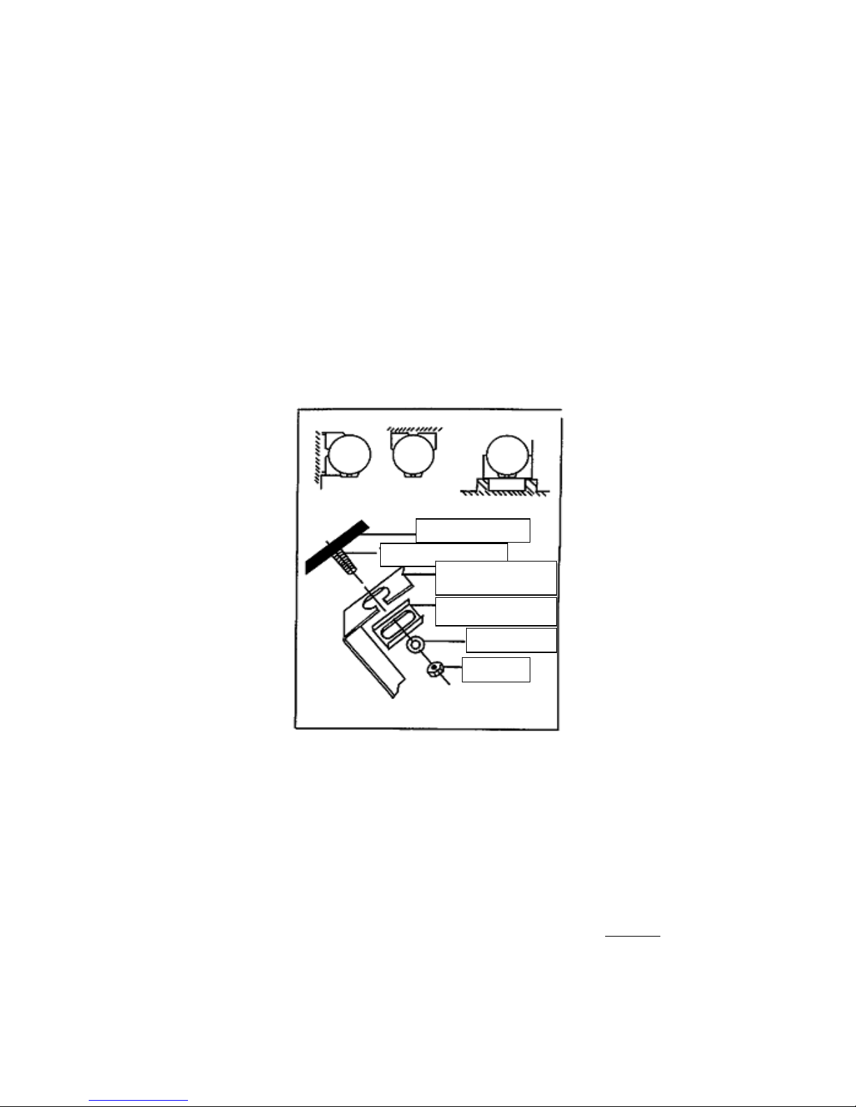
Horizontal: there are 3 possibilities for installation:
WARNING! Once the water heater is in place, the water entry and exits tubes must be
in a vertical position below the water heater. Leave free space in the heating element of
a minimum of 400 mm.
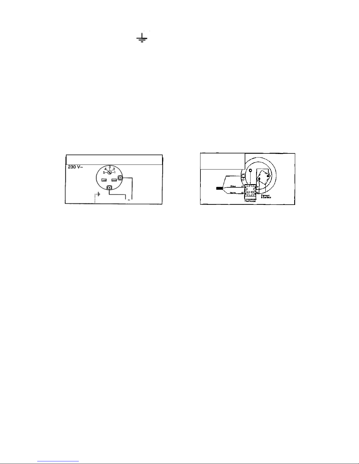
HYDRAULIC CONNECTION
Before making the hydraulic connection, it is essential to clean the entry tubes in order
to prevent the entry of metal and foreign particles into the water heater. Warning: Never
connect the water entry and exit points directly to the tubing because this would cause
galvanic pairs that generate corrosion. It is compulsory to employ anti-electrolytic pipe
couplings on the entry points. If there were corrosion in the tank and the apparatus had
no pipe couplings, the guarantee would be invalidated.
WALL OR CEILING
ATTACHMENT
ATTACHMENT
SUPPORT
ATTACHMENT PIECE
WASHER
NUT

LOW PRESSURE ASSEMBLY. If supply pressure exceeds 5.5 bars, it is compulsory
to install a pressure reducer in the entry point of the house. Recommended pressure is
from 3 to 4 bars.
The installation is made with a 7 bar membrane safety valve connected to the water
entry of the water heater equipped with an anti-return device. The apparatus is only
guaranteed if it is equipped with this accessory and respects the installation outlines
described in this manual.
The drainage or flow of water arising from excess pressure must never be obstructed.
This means the drainage tube must be sufficiently sloped and continuous. And its
section can never be smaller than the orifice of the safety valve outlet. No type of
hydraulic accessory can be installed between the safety valve and the cold water entry.
We recommend the installation of a siphon funnel connected to the drainage in order to
easily verify the workings of the safety valve.
During the water heating period, it dilates, so some of the water is lost in drips through
the drainage (approximately 3% of the capacity per heating cycle). Do not worry, this is
a normal phenomenon.
HYDRAULIC OUTLINE
Low pressure water heater assembly
75-100450400 L
ELECTRICAL CONNECTION
The water heater is equipped with a thermostat with dry contacts that can only work in
alternating current networks. The connection must be made in line with the outlines
printed on the cover of the electrical protection.
The installation must be made with an omnipolar cut-off device with a contact opening
distance of at least 3 mm. This apparatus is not designed to be connected to an
optimizing relay.
-The apparatus must be connected to a fixed channelling with a rigid cable with a
section of 2.5mm2.
Hot water tube Cold water tube
Safet
y
g
rou
p
or valve Reducer for pressure
above 5.5 bars
Cut-off valve
Empty – Drainage
Safety group or valve
Reducer for pressure
above 5.5 bars
Cold water tube
Cut-off valve
Siphon funnel
Empty – Drainage
Hot water exit

-The earth of the apparatus is compulsory (there is a connection with the
following symbol ). You must ensure it is connected to a fixed socket
with an earth device.
Thermostat: It is a high quality component built, calibrated and monitored carefully.
Its mission is to maintain and limit the temperature of the water at a chosen value. It is
sealed and must never be subjected to adjustments or repairs except for its normal
regulation by means of the rotation of the indicator, which can only be carried out by
qualified personnel after disconnection from the network. Not respecting this point
invalidates the guarantee.
In order to economize electrical energy consumption, the calibrated temperature of the
water heaters has been limited in the factory to approximately 65ºC; resistance to
corrosion and calcareous deposits is therefore also improved.
Safety thermal limit control: All our water heaters are equipped with a safety thermal
limit control that disconnects the heating element if the temperature reaches an
abnormal level.
The thermal limit control is integrated into the thermostat. In the event that the water
heater is disconnected by the safety thermal limit control, verify the installation before
setting it up again.
Never bridge across the thermal safety!
Armoured horizontal 150-200 L Ceramic
vertical

SETUP
WARNING! Never connect the apparatus without it being full of water.
It is necessary to completely ‘drain’ the water heater, the tubes and the taps of air that
could be inside to avoid disagreeable noises. Before connecting the water heater to the
network, fill it completely with water by leaving the hot water tap on. Do not turn the
tap off until the water exits evenly and without noise through the tubes and turn other
taps on successively.
MAINTENANCE
IMPORTANT: On a regular basis (once a month) the safety valve must be placed
in the emptying position in order to check it is not obstructed. If it were, it must be
replaced by a new one.
In areas where the water has high lime content, we recommend an annual cleaning of
scale: 1 – Turn off the electric current. 2 – Empty the water heater of water using the
safety valve. 3 – Disassemble the heating element and the thermostat by removing the
attachment screws. 4 – Remove the scale deposited as balls or sheets at the bottom of
the tank and carefully clean the components in contact with the water. Do not remove
the scale attached to the wall of the tank, since this constitutes an effective protection
against corrosion. 5 – After cleaning, assemble the components once again and replace
the connection flange. 6 – Set the water heater up again as described in the “setup”
section.
If you notice the continual escape of vapour or boiling water through the drainage outlet
or when you turn on a tap, turn of the electrical input and notify the Technical Help
Service.
As part of the policy of continuous product improvement, ELNUR S.A. reserves the right to alter specifications without notice.
This manual suits for next models
2
Table of contents
Other Gabarron Water Heater manuals
Popular Water Heater manuals by other brands

Premier Equestrian
Premier Equestrian Water Wagon Setup guide

Profile
Profile P4AAKASBRTD owner's manual

HTP
HTP Hydra Smart RT-150 Series User's information manual

Radiant
Radiant SF 14 user manual

Eurofred
Eurofred daitsu WITD-AQUATANK HP Series Installation and maintenance manual

Eccotemp
Eccotemp EL5 manual