GAGEMAKER MIC TRAC MT-4000 User manual

M
MI
IC
C
T
TR
RA
AC
C
M
MT
T-
-4
40
00
00
0
OPERATION MANUAL

M
MI
IC
C
T
TR
RA
AC
C
M
MT
T-
-4
40
00
00
0
O
Op
pe
er
ra
at
ti
io
on
n
M
Ma
an
nu
ua
al
l
2
©2012 Gagemaker, Inc.
OMMT400012-99

M
MI
IC
C
T
TR
RA
AC
C
M
MT
T-
-4
40
00
00
0
O
Op
pe
er
ra
at
ti
io
on
n
M
Ma
an
nu
ua
al
l
3
Contents
Introduction
What is the MIC TRAC Measurement System? 7
Gagemaker’s Philosophy of Accuracy 7
Technical Support 7
Unpacking and Handling 8
Returning the MIC TRAC 10
System Components
Component List 11
MIC TRAC Base Unit Component Descriptions 12
MIC TRAC Setup Procedures
Removing Lifting Lugs 15
Releasing the Weight Holder 16
Connecting the Computer 18
Connecting the MIC TRAC to the Computer 20
Setting Up the Optional Support Table 21
Finding Home Position on the MIC TRAC 22
Changing the Measuring Force Direction 23
Mounting the Carbide Anvils (TF-2R Blocks) 25
Measurement Procedures
Measuring Parts 29
Care and Maintenance
Maintenance Tips 31
Maintenance Note 31
Safety Tips 31
MIC TRAC Calibration 32
Warranty Information 32
Technical Information
Specifications 33
Cable Wiring Diagrams 34
Weight System 35
General Dimensions 36

M
MI
IC
C
T
TR
RA
AC
C
M
MT
T-
-4
40
00
00
0
O
Op
pe
er
ra
at
ti
io
on
n
M
Ma
an
nu
ua
al
l
4

M
MI
IC
C
T
TR
RA
AC
C
M
MT
T-
-4
40
00
00
0
O
Op
pe
er
ra
at
ti
io
on
n
M
Ma
an
nu
ua
al
l
5
Congratulations! Your decision to purchase a Gagemaker product above all others on the market
demonstrates your confidence in our quality and workmanship.
This precision measurement center will quickly become one of the most important pieces of equipment in
your facility. The MIC TRAC™ System has developed into what it is today due to response to the needs
of industries just like yours. The MIC TRAC System addresses gage setting and calibration issues that
were never possible before. All it takes is a little imagination.
But, for those who don’t have time to imagine, Gagemaker provides gages and fixtures to accompany the
MIC TRAC to make your job easier and more precise.
To ensure the high performance and operation of our product, we urge you to use the included reference
materials. They contain important information for proper set up and use of the equipment. Also, we
recommend that you follow the care and maintenance tips in this manual to keep the equipment working
in top condition.
If your questions have not been addressed in our reference materials, contact your local
representative or a customer service representative at 713-472-7360.

M
MI
IC
C
T
TR
RA
AC
C
M
MT
T-
-4
40
00
00
0
O
Op
pe
er
ra
at
ti
io
on
n
M
Ma
an
nu
ua
al
l
6

M
MI
IC
C
T
TR
RA
AC
C
M
MT
T-
-4
40
00
00
0
O
Op
pe
er
ra
at
ti
io
on
n
M
Ma
an
nu
ua
al
l
7
Introduction
What is the MIC TRAC?
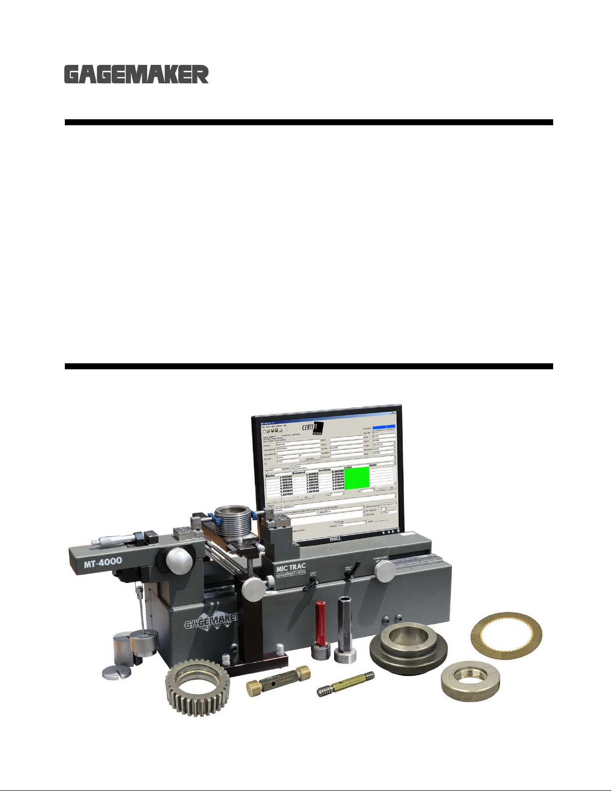
The MIC TRAC™ System is an electronic, adjustable calibration and measurement center that will
improve your ability to inspect parts, preset indicator style gages, and calibrate a variety of hand held
inspection gages, as well as non-split, cylindrical ring and plug gages.
The MT-4000 measurement system includes the base unit, which houses an optical scale. This glass
scale provides the MIC TRAC with its precision measuring capability with accuracies to .00005”. The
base unit includes receiver pads and anvils that are manufactured and precision ground to within .00005”
to provide parallel surfaces for measuring. The MT-4000 also contains a weight system that supplies the
necessary measuring forces to meet national standards.
For gage calibration, this system comes complete with a computer containing the CERTIFI Software.
The software is an integrated package. The software is comprised of a computerized digital readout
(INSPEX), calibration report writer, and a database (Recall Database) for tracking gage information.
Refer to the CERTIFI Software manual for information about using this software.
As an option, the MT-4000 measurement system includes the CAL-PAK, for calibrating gages. The CAL-
PAK is an assortment of fixtures that attach to the base unit for holding gages securely during the
calibration process. Proper positioning of the gage improves the accuracy of the calibration and provides
more consistent results. Refer to the MIC TRAC MT-4000 Calibration Reference Cards and the Gage
Calibration Setup Poster for information about using the CAL-PAK fixtures.
Gagemaker’s Philosophy of Accuracy
Over a decade of research and development of calibration and measuring equipment has provided us
with many eye opening experiences into the realities of what accuracy means. Accuracy is subjective.
Accuracy is controlled by many physical elements, all of which have their own variables. Temperature
and humidity are just two factors that can affect accuracy.
It is critical to stabilize, monitor and adjust both temperature and humidity in order to maintain an
accurate environment. 68°F (20°C) and 50% humidity have been established by NIST as the
temperature at which measurements should be taken. Measurement or calibration in any other
environment should be evaluated prior to certification.
All equipment manufactured by Gagemaker LP is accurate when operated according to our instructions
and under suitable environmental conditions. In many cases, to improve accuracy, you may need to
improve environmental conditions.
Technical Support
Phone: 713-472-7360
Hours: Monday – Friday 8AM – 5PM (CST)
Product Information and Updates
Visit our web site at: www.gagemaker.com

M
MI
IC
C
T
TR
RA
AC
C
M
MT
T-
-4
40
00
00
0
O
Op
pe
er
ra
at
ti
io
on
n
M
Ma
an
nu
ua
al
l
8
Unpacking and Handling
Before removing the unit, be sure you have a flat, secure surface to place it on. A granite or
marble surface is ideal to reduce vibration, but a good solid wood top bench with sturdy legs
is acceptable. Also, since the MIC TRAC requires an electrical power source, locate the unit
within four feet of an electrical outlet.
1. After opening the cover of the shipping carton,
check for signs of damage.
Note: If the unit appears damaged, contact
Gagemaker immediately at 713-472-7360.
2. To release the unit from the shipping carton,
loosen and remove the wing nuts and washers.
3. Remove the wood strips. The unit is ready to
be lifted from the shipping carton.
4. For removing the unit, there are four lifting lugs
attached to the sides of the MIC TRAC.
5. Secure two 36" X ¾" durable lifting
straps around the lifting lugs on each
side.

M
MI
IC
C
T
TR
RA
AC
C
M
MT
T-
-4
40
00
00
0
O
Op
pe
er
ra
at
ti
io
on
n
M
Ma
an
nu
ua
al
l
9
Unpacking and Handling (continued)
6. Since the MT-4000 weighs in excess of 100
pounds, use a crane or hoist to remove it from
the shipping carton and place it on a secure
surface. If this is not available, we recommend
using two people to lift the unit out of the
shipping carton.
Lift the unit from the shipping carton by
picking up on the bottom only. Do not
use the upper carriage.
7. Once in place, clean all bare metal surfaces to
remove any debris from packaging and
shipping and apply a thin coat of lightweight
gage oil to these surfaces.
8. After unpacking the MIC TRAC do not destroy
or discard the shipping carton or shipping
materials. If for any reason you need to return
the MIC TRAC to our factory, you'll need to use
the original shipping carton.
If the unit is returned in any container
other than the original shipping carton,
there will be a charge of $150.00 for
carton replacement when the gage is
returned to you.
Gagemaker is not responsible for any
damages incurred during return
shipment due to poor packing.

M
MI
IC
C
T
TR
RA
AC
C
M
MT
T-
-4
40
00
00
0
O
Op
pe
er
ra
at
ti
io
on
n
M
Ma
an
nu
ua
al
l
10
Returning the MIC TRAC
1. Contact Gagemaker for a Return Authorization Number at 713-472-7360.
No shipments will be accepted without a Return Authorization Number.
2. If you have removed the lifting lugs, reattach them before shipping the unit back to the factory.
3. Attach the bracket, originally shipped with the MIC TRAC, to the weight holder to secure the
weight system during shipping.
4. Tighten the coarse adjust and fine adjust locks before packing the unit.
5. Place two 36" X ¾" durable lifting straps around the lifting lugs and place the unit in the original
shipping carton. The lifting lugs will fit into the grooves in the bottom of the carton.
If the unit is returned in any container other than the original shipping carton, there will be a
charge of $525.00 for carton replacement when the gage is returned to you. Gagemaker is
not responsible for any damages incurred during return shipment due to poor packing.
6. Place the wood strips over the bolts in the shipping carton.
7. Place the washers and wing nuts over the boards and tighten.
8. Close the lid and secure the flap to the velcro on the side of the carton.
9. Secure the three strap latches on the outside of the shipping carton.
10. Secure the shipping carton to a pallet.
11. Display the Return Authorization Number clearly on the shipping carton.
12. Ship to the following address by motor freight only. UPS shipments will not be accepted.
Gagemaker
712 East Southmore Ave.
Pasadena, Texas 77502
MIC TRAC Secured in Original Shipping Carton

M
MI
IC
C
T
TR
RA
AC
C
M
MT
T-
-4
40
00
00
0
O
Op
pe
er
ra
at
ti
io
on
n
M
Ma
an
nu
ua
al
l
11
System Components
Take some time to become familiar with all the parts that make up the MIC TRAC system by
reviewing the labeled diagram and descriptions that follow. The part names are important to
understand the assembly and operating instructions.
Component List
Item
Description
Quantity
1 MIC TRAC Base Unit 1
2 Right Carriage (Y Axis) 1
3 Y Axis Adjust Knob 1
4 Y Axis Locks 2
5
Weight System (includes weight holder, compensator
and 2 weights)
1
6 X Axis Adjust Knob 1
7 Left Carriage (X Axis) 1
8 Fine Adjust Spindle 1
9 Carbide Anvils (TF-2R Blocks) 2
10 Receiver Pads 2
11 X Axis MT Cable 1
12 Y Axis MT Cable 1
13 MT-4-USB 1
14 USB Data Link Cable 1
15 CPU Power Cable (may not include transformer box) 1
16 Mouse (may be wireless) 1
17 Keyboard (may be wireless) 1
18 CPU (Central Processing Unit, all-in-one computer) 1
1
3
4
2
10
8
7
6
5
18
17
16
15
12
14
11
13
9

M
MI
IC
C
T
TR
RA
AC
C
M
MT
T-
-4
40
00
00
0
O
Op
pe
er
ra
at
ti
io
on
n
M
Ma
an
nu
ua
al
l
12
MIC TRAC Base Unit Component Descriptions
Receiver Pads
Located on the right and left carriages
and are used to hold fixtures, such as the
carbide anvils (TF-2R blocks). The
receiver pads are ground in matched sets
so the mounting surfaces are flat and
parallel.
Y Axis Adjust Knob
Used for positioning the right receiver
pad. This knob moves the carriage left
and right in large increments (4.000” with
each revolution) and is used for quick
positioning.
X Axis Adjust Knob
Used for moving the left receiver pad left
and right. Pulling out on this knob
releases the left carriage, which allows it
to float during a measurement and
eliminates any mechanical interference.
Only release the X axis adjust
knob once you reach the point of
measurement.
Y Axis Locks
(Lock 1 and Lock 2)
Secure the left carriage during
measurement.
Do not attempt to turn the Y axis
adjust knob when the locks are
secured.
Fine Adjust Spindle
Located on top of the left carriage. This
knob moves the left receiver pad in small
increments and allows for close
positioning. The spindle provides for
approximately 1.00” of fine adjustment.

M
MI
IC
C
T
TR
RA
AC
C
M
MT
T-
-4
40
00
00
0
O
Op
pe
er
ra
at
ti
io
on
n
M
Ma
an
nu
ua
al
l
13
MIC TRAC Base Unit Component Descriptions (continued)
Weight System
Includes a weight holder and three
weights. Weights consist of: internal
measurement compensator (4 oz), a 1.0
lb, and 2.0 lbs. weights. During the
measurement process, the weights are
used to achieve the recommended
measuring force. The internal
compensator is used to overcome the
spring pressure of the probe when set for
internal measurements. The direction of
the measuring force is determined by the
position of the force lugs (refer to the
procedure for Changing the Measuring
Force Direction in this manual).
Support Table
(Optional)
Used to support parts or gages during
measurement. The adjustable height
support base includes clamps that hold
the work piece for measuring.

M
MI
IC
C
T
TR
RA
AC
C
M
MT
T-
-4
40
00
00
0
O
Op
pe
er
ra
at
ti
io
on
n
M
Ma
an
nu
ua
al
l
14

M
MI
IC
C
T
TR
RA
AC
C
M
MT
T-
-4
40
00
00
0
O
Op
pe
er
ra
at
ti
io
on
n
M
Ma
an
nu
ua
al
l
15
MIC TRAC Setup Procedures
The accuracy and repeatability of your MIC TRAC depends on the correct attachment of the
components. If the components are attached improperly, the gage will perform incorrectly.
Each of the procedures on the following pages will help you to setup your MT-4000 properly.
Removing Lifting Lugs (Optional)
Materials Needed:
•MIC TRAC MT-4000 base unit
•3/8" and 5/16" hex wrenches
•Button head cap screws (included with unit)
When the unit is in place, you may want to remove the (4) lifting lugs. However, if you do remove
the lugs, keep the lugs and bolts handy. You will need to reattach them if the unit needs to be
relocated or shipped back to the factory.
1. Remove the four lugs with a 3/8" hex wrench.
2. Replace each lug bolt with one of four
button head cap screws, using a 5/16"
hex wrench.

M
MI
IC
C
T
TR
RA
AC
C
M
MT
T-
-4
40
00
00
0
O
Op
pe
er
ra
at
ti
io
on
n
M
Ma
an
nu
ua
al
l
16
Releasing the Weight Holder
Materials Needed:
•MIC TRAC MT-4000 base unit
•1/8" hex wrench
•Lightweight gage oil
The weight holder on the MT-4000 is secured in place for shipping. It is important to
remove the shipping bracket before using the equipment.
1. Remove the foam wrapping from the weight
holder.
2. Turn the fine adjust spindle on top of the left
carriage counterclockwise to loosen.
3. Turn the X axis adjust knob
counterclockwise until the weight holder
releases.
4. Using a 1/8" hex wrench, remove the bracket
from the weight holder.
Note: Be sure to keep the bracket in case the unit
needs to be shipped back to the factory.

M
MI
IC
C
T
TR
RA
AC
C
M
MT
T-
-4
40
00
00
0
O
Op
pe
er
ra
at
ti
io
on
n
M
Ma
an
nu
ua
al
l
17
Releasing the Weight Holder (continued)
5. Be sure that the cords that hold the weights are
properly seated on their pulleys (refer to the
Weight System diagram at the back of this
manual).
Note: During the measurement process, you will
place the proper combination of the three
weights on the weight holder to achieve the
necessary measuring force.

M
MI
IC
C
T
TR
RA
AC
C
M
MT
T-
-4
40
00
00
0
O
Op
pe
er
ra
at
ti
io
on
n
M
Ma
an
nu
ua
al
l
18
Connecting the Computer
Materials Needed:
•All-In-One Computer •Wireless plug-in module
•
Power cord
•Wireless Keyboard
•Wireless Mouse
The computer, which is included with the MT-4000, should be used exclusively with the MIC
TRAC. We recommend that you do not install other software programs on this computer. The
CERTIFI Software is a 32-bit Windows based calibration program that comes installed on the
computer.
1. Plug the female end of the power cord into the
power port on the back of the Computer. Plug
the other end of the power cord into an
electrical outlet.
2. Plug the keyboard/mouse wireless module into
one of the USB ports on the back of the
Computer.
3. Plug the USB Data Cable into one of the USB
ports on the back of the computer.
4. Install AA batteries into the mouse and
keyboard.
Inserting
power cord
Inserting wireless module Inserting USB Data cable
Installing batteries in keyboard and mouse

M
MI
IC
C
T
TR
RA
AC
C
M
MT
T-
-4
40
00
00
0
O
Op
pe
er
ra
at
ti
io
on
n
M
Ma
an
nu
ua
al
l
19
Connecting the Computer (continued)
5. If you have a printer, plug the USB printer cable
into one of the USB ports on the back of the
computer. Refer to the instructions that came
with your printer, if you need additional help
connecting the printer.
Inserting USB cable to printer

M
MI
IC
C
T
TR
RA
AC
C
M
MT
T-
-4
40
00
00
0
O
Op
pe
er
ra
at
ti
io
on
n
M
Ma
an
nu
ua
al
l
20
Connecting the MIC TRAC to the Computer
Materials Needed:
•MIC TRAC MT-4000 base unit
•USB Data Cable
•MT-4-USB Interface Box
The data link cable feeds information from the MIC TRAC to the computer. It has a large connector on
one end and three small connectors on the other end. The small connectors represent the X axis, Y axis,
and an optional remote switch, which can be used for saving measurements during calibration without
using your mouse.
1. Plug the B end of the USB Data Cable into the
data port on the backside of the MT-4-USB
box.
2. Plug the X axis data cable into the X axis port,
and the Y axis cable into the X axis port of the
MT-4-USB box.
Table of contents
Other GAGEMAKER Industrial Equipment manuals
Popular Industrial Equipment manuals by other brands

ADCA
ADCA FLT16 Series Installation and maintenance instructions

Giacomini
Giacomini R553FPDB instruction manual

Vestil
Vestil P-HOP Series quick start guide

WNT
WNT ZSG mini 100 Installation and operating instructions

Aerotech
Aerotech ALAR LP Series Hardware manual

CTC Giersch
CTC Giersch RG20 Technical information installation instructions

ABB
ABB HT612326 Operation manual

ITW Gema
ITW Gema EASY 1-L Operating instructions and spare parts list

Aeroflex
Aeroflex S Series instruction manual

HOLZMANN MASCHINEN
HOLZMANN MASCHINEN ZX7045 operating manual

ProMinent
ProMinent CHLORINSITU V operating instructions

Mid-West Instrument
Mid-West Instrument 522 Installation and operating instruction