GAGEMAKER PN-3000 Series User manual

Pin Nose Gages and Seal Gage Operation Manual
Pin Nose Gages and Seal Diameter Gages
OPERATION MANUAL
PN-3000SERIES

Pin Nose Gages and Seal Gage Operation Manual
2

Pin Nose Gages and Seal Gage Operation Manual
3
Introduction
Technical Support 5
Product Information and Updates 5
System Components
PN-3001/2/3 Ext. 6
PNI-3001/2/3 VMB Int. 7
PNA-3001/2/3 VMA Ext. 8
PN-31VM-30 Int./Ext. 9
PN-33VM-30 Int./Ext. 9
PN-3001/2/3 JFE Ext. 10
Setting Standards
Box or Pin Fram Standards 11
Box or Round Standard 11
Full Form Box or Pin Sitting Standard 11
PNS-3000 Pin Seal Gage Setting Master 12
PN-3000/T Pin Seal Standoff Plates 12
Setup Procedures
PN-3001/2/3 Ext. 13
PNI-3001/2/3 VMB Int. 14
PNA-3001/2/3 VMA Ext. 15
PN-31VM-30 Int./Ext. 16
PN-33VM-30 Int./Ext. 16
PN-3001/2/3 JFE Ext. 17
Care and Maintenance
Maintenance Tips 18
Warranty Information 18
CONTENTS

Pin Nose Gages and Seal Gage Operation Manual
Congratulations! Your decision to purchase a Gagemaker product above all others on the market
demonstrates your confidence in our quality and workmanship.
To ensure the high performance and operation of our product, we urge you to use the included
reference materials. They contain important information for proper installation, setup, and use of
the equipment. Also, we recommend that you follow the care and maintenance tips in this
manual to keep the equipment working in top condition.
If your questions have not been addressed in our reference materials, contact your local
representative or a customer service representative at 713-472-7360.
4

Pin Nose Gages and Seal Gage Operation Manual
ThePin Nosegages measurecritical pinseal diametersand widths.These gagesadjust
to cover all sizes ofseal diameters. The standard pin nose gage measures seal
diameters from 2 3/8” – 13 3/8”.
ThePin Nose can be used to measurestraight ortapered seal diameters, shallow bores,
andholelocations.
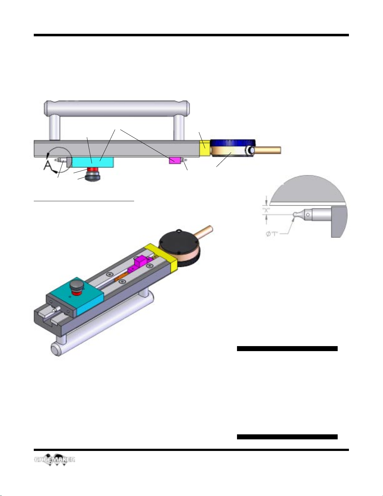
The pin nose gages use precision contact points to accurately measure the ring groove
diameter and width at the critical sealing point of the face groove.
Before inspecting parts, the pin nose gages must be preset to a nominal predetermined
dimension. The Seal Inspection Tolerances and Setting Dimension tables in this manual
determine the gage’s setting dimensions and gauging tolerances. The pin nose gages can be
preset using gage blocks, Frame Standards, or Gagemaker’s Pin Nose Diameter Gage
SettingMaster.
To inspect parts, the contact points are placed in the seal of the part and the gage is
positioned by sweeping to obtain an indicator reading. Gage indicators show actual deviation
from the preset master dimension. Taking measurements in several different locations along
the seal will provide an average seal diameter or width. It is also recommended that the gage
be zeroed periodically during use to maintain accurate readings.
Technical Support
Phone: 713-472-7360
Hours: Monday – Friday 8AM – 5PM (CST)
Product Information and Updates
Visit our web site at: www.gagemaker.com
INTRODUCTION
5

Pin Nose Gages and Seal Gage Operation Manual
PN-3001 PinNoseDiameterGage 23/8"-51/2" (0"-5.750")
PN-3002 PinNoseDiameterGage 6"-95/8" (0"-9.750")
PN-3003 PinNoseDiameterGage 10"-133/8" (0"-13.750")
PN-3001/2/3 Ext.
SystemComponent
HOW TO ORDER
1.SelectthePN-3001Ext.Seriesgage
model,based on the size oftheconnector.
2. Specify the distance from the face of the
connectorto themeasuringplane “X”.
3.Specifythe contactpoint diameter“T”
neededforselection of the proper contact
points(not included in the priceofthe gage
andsold individually).
Specifythestand-offplatemodel,ifnecessary
“Y” (sold separately).
1 Dial Indicator (#803) 1
2 Contact Points 2
3 EndCap/SliderAssembly(FactoryInstalled)
4 Slider Knob 1
5 Slider Spacer 1
6 T-Nut 1
Item Description Qty
6
21
3
6
4
5
PN-3000/T
StandoffPlates
(2perset)
CustomertoSpecity
ThicknessofTaperPlates
(SeePage12)
CustomertoSupply
StandoffandPointSize

Pin Nose Gages and Seal Gage Operation Manual
PNI-3001/2/3 - VMB Int.
SystemComponent
Item Description Qty
1 Dial Indicator (#803) 1
2 Contact Points 2
3 SliderAssembly (FactoryInstalled)
4 Slider Knob 1
5 Slider Spacer 1
6 T-Nut 1
7 End Cap 1
8 Point Extension (#PE 500) 1
7
(A)CustomertoSupply
StandoffandPointSize
PNI-3001-VMB Internal “Ball Contact” Seal Diameter Gage 2 3/8"-5 1/2"
PNI-3002-VMB Internal “Ball Contact” Seal Diameter Gage 6" - 9 5/8"
PNI-3003-VMB Internal “Ball Contact” Seal Diameter Gage 10" - 13 3/8"
1
2
3
4
5
67
8
HOW TO ORDER
1.SelectthePN-3001Ext.Seriesgage
model,based on the size oftheconnector.
2. Specify the distance from the face of the
connectorto themeasuringplane “X”.
3.Specifythe contactpointdiameter “T”
neededforselection of the proper contact
points(not included in the priceofthe gage
andsold individually).

Pin Nose Gages and Seal Gage Operation Manual
PNA-3001-VMA 30° External Apex Diameter Gage, Anvils 2 3/8" - 5 1/2"
PNA-3002-VMA 30° External Apex Diameter Gage, Anvils 6" - 9 5/8"
PNA-3003-VMA 30° External Apex Diameter Gage, Anvils 10" - 13 3/8"
PNA-3001/2/3 -VMA Ext.
System Components
HOW TO ORDER
1.Select thePNA-3001 Ext. Series gages
model,based on the size oftheconnector.
Item Description Qty
1 Dial Indicator (#803) 1
2 Upper Anvil (Factory Installed) 1
3 Lower Anvil 1
4 Slider Block 1
5 Slider Knob 1
6 Slider Spacer 1
7 T-Nut 1
8 End Cap 1
8
1
2
3
4
5
6
78

Pin Nose Gages and Seal Gage Operation Manual
PN-31VM-30 Int./Ext.
PN-33VM-30 Int./Ext.
System Components
Item Description Qty
9
PN-31VM-30 30° Internal/ExternalApexSealDiameter“V” 23/8"-65/8"Int4"-65/8"Ext
PN-33VM-30 30° Internal/ExternalApexSealDiameter“V” 23/8"-14"Int/4"-14"Ext
1 Dial Indicator (#803) 1
2 Upper Anvil (Factory Installed) 1
3 Lower Anvil 1
4 Slider Block 1
5 Slider Knob 1
6 Slider Spacer 1
7 T-Nut 1
8 End Cap 1
1
2
3
4
5
6
78
7
HOW TO ORDER
1.SelectthePN-31/33VM Ext.Series gages
model,based on the size oftheconnector.

Pin Nose Gages and Seal Gage Operation Manual
PN-3001/2/3 JFE Ext.
System Components
HOW TO ORDER
1.SelectthePN-3001JFEExt.Series
gagesmodel, based on the sizeofthe
connector.
ContactJFE forpoint sizs.
PN-3001JFE External SealDiameter 2 3/8”-5”
PN-3002 JFE External Seal Diameter 2 3/8”-9 5/8”
PN-3003JFE External Seal Diameter 2 3/8”-13 3/8”
No Parts or Assembles
Available from Factory
10
1
2
3
5
67
4
Item Description
1 DialIndicator (#863)
2 SpecialContact Point
3 LowerAnvil
4 Slider T-Nandle
5 Slider Spacer
6 T-Nut
7 SliderBlock
8 End Cap
8

Pin Nose Gages and Seal Gage Operation Manual
SETTING STANDARDS
Box or Pin
Frame Standards
Boxor PinRoundStandard
Full Form Box or Pin
SettingStandard
The Full Form Flat style setting standards are
designed to preset all models of the PN-
3000 JFE Series gages for accurate
inspection of API pin end seal and seal taper
diameters of premium connectors. These
standards consist of a rigid, non-adjustable
steel block precision machined to proper size
to tolerances of ±.0003".
The round and frame style setting standards
are designed to preset all models of the PN-
3000 Series gages for accurate inspection of
API pin end seal and seal taper diameters of
premium connectors. These standards
consist of a rigid, non-adjustable steel block
precision machined to proper size to
tolerances of ±.0003".
11
For API threads and ring grooves, Gagernaker
manufacturessettingstandardsdesignedtothe
latestAPIstandards and tolerances.
ForpremiumconnectionsGagemaker
manufacturessettingstandardstoour
customersrequirements.
Gagemakerwillnot manufacture premium
connectionsetting standards for a third party
without the written permission of the premium
connectionowner.

Pin Nose Gages and Seal Gage Operation Manual
SETTING STANDARDS
PNS-3000
Pin Seal Gage
Setting Master
PN-3000/T Pin Seal Standoff Plates (2 per set)
(See Page 6)
ThePNS-3000pinsealdiameter gage setting
standard is an adjustable standard used to preset
thePN-3000seriespinsealgages.ThePN-3000
gages use a dial indicator to compare a known
diameterto the diameter of the machinedpiece.
ThePNS-3000is adjusted to any diameter within
the range of the standard. The standard is easy to
setupandprovidesanaccuratemaster on which
tonullthePN-3000 indicator.
ThePNS-3000has two adjustable blocks that ride
on 2 precision ground rails. The upper block is
connectedto a fine adjustment thumbscrew,the
lower block slides on the rails and is locked in
place with 2 setscrews located on the bottom of
the block.
Thecontact points of the PN-3000 gagecontact
thehardened pads that are insetintothe upper
andlowerblocks. The setting dimension for the
standardis the dimension over these2 pads.
12
PNT-3000TaperPlatesforPN-3001/2/3Gages
SizesnotListedareAvailableuponCostomer’sRequest.

Pin Nose Gages and Seal Gage Operation Manual
PN-3001/2/3 Ext.
Setup Procedures
Sweep Gage to
Locate Largest Indicator
Reading
StandoffPlates
AvailableinaVariety
ofThickness
seePage12
The round and frame style setting standards are designed to preset
all models of the PN-3000 Series gages for accurate inspection of
API pin end seal and seal taper diameters of premium connectors.
These standards consist of a rigid, non-adjustable steel block
precision machined to proper size to tolerances of ±.0003".
13

Pin Nose Gages and Seal Gage Operation Manual
PNI-3001/2/3 Int.
Setup Procedures
Sweep Gage to
Locate Largest Indicator
Reading
The round and frame style
setting standards are
designed to preset all
models of the PN-3000
Series gages for accurate
inspection of API pin end
seal and seal taper
diameters of premium
connectors. These
standards consist of a rigid,
non-adjustable steel block
precision machined to
proper size to tolerances of
±.0003".
14

Pin Nose Gages and Seal Gage Operation Manual
PNA-3001/2/3 Ext.
Setup Procedures
Sweep Gage to
Locate Largest Indicator
Reading
The round and frame style
settingstandardsaredesigned
to preset all models of the PN-
3000 Series gages for
accurate inspection of API pin
end seal and seal taper
diameters of premium
connectors. These standards
consist of a rigid, non-
adjustable steel block
precision machined to proper
size to tolerances of ±.0003".
15

Pin Nose Gages and Seal Gage Operation Manual
PN-31VM-30 Int./Ext.
PN-33VM-30 Int./Ext.
Setup Procedures
Int.
Ext.
Sweep Gage to
Locate Largest Indicator
Reading
The round and frame style setting
standards are designed to preset
all models of the PN-3000 Series
gages for accurate inspection of
API pin end seal and seal taper
diameters of premium connectors.
These standards consist of a rigid,
non-adjustable steel block
precision machined to proper size
to tolerances of ±.0003".
16

Pin Nose Gages and Seal Gage Operation Manual
PN-3001/2/3 JFE Ext.
Setup Procedures
Ext.
Sweep Gage to
Locate Largest Indicator
Reading
The Full Form Flat style setting
standards are designed to preset all
models of the PN-3000 JFE Series
gages for accurate inspection of API
pin end seal and seal taper diameters
of premium connectors. These
standards consist of a rigid, non-
adjustable steel block precision
machined to proper size to tolerances
of ±.0003".
17

Pin Nose Gages and Seal Gage Operation Manual
Maintenance Tips
•Keep all unprotected metal surfaces coated with light oil.
•Avoid dropping the gage or subjecting it to any vibration or impact.
•Keep the gage dry and away from any machine coolant spray.
•Do not force the movement of any of the mechanical parts. The mechanics are
designed to move freely.
•Keep the indicator face clean.
Warranty Information
GAGEMAKER warrants its products to be free from defects in material and
workmanship for one year from the date of shipment.At our option, we will repair or
replace any defective product upon return, prepaid, properly packed to our factory in
Pasadena, Texas. This warranty applies to all products when used in a normal
industrial environment.Any unauthorized tampering, misuse or neglect will make this
warranty null and void. Under no circumstances will GAGEMAKER or any affiliate
have any liabilities for loss or for any indirect or consequential damages. The
foregoing warranties are in lieu of all other warranties expressed or implied, including
but not limited to, the implied warranties of merchantability and fitness for a particular
purpose.
CARE and MAINTENANCE
18

Pin Nose Gages and Seal Gage Operation Manual
19
The following diagrams display the proper setup
and operation of the PN-3000 Pin Seal Diameter
Gage.
1. Adjust the lower block of the PN-3000 gage to
a location that the contact points or Anvil fit
around the seal diameter of the setting standard.
2. Continue to adjust the lower block position
until adequate preload of the indicator has been
achieved. Lock the lower block lock knob. Normal
preload is approximately 1/2 - 1 revolution.
3. Sweep the gage to locate the largest indicator
reading (the point a which the indicator needle
changes direction). When the largest diameter is
located, rotate the indicator bezel to align the
zero with the needle. Tighten the indicator bezel
clamp.
4. Remove the gage from the standard and
place the gage against the connector face.
5. Using the lower (fixed) contact point or Anvil
as a pivot, sweep to locate the largest reading.
6. When the largest reading has been located,
record the deviation from zero on the proper
inspection report form.
Slider
Knob
Tapered
Seal
Surface Zero
Indicator
Round
Setting
Standard
RecordDeviation
TaperedSeal
Slider
Block
SweepGageto
LocateLargestIndicator
Reading
GAGE OPERATION
Connector

Pin Nose Gages and Seal Gage Operation Manual
Gagemaker, LP, P.O. Box 87709, Houston, Texas 77287-7709
712 East SouthmoreAve., Pasadena, Texas 77502
Phone:713-472-7360
Fax:713-472-7241
Web site: www.gagemaker.com
This manual suits for next models
14
Table of contents
Other GAGEMAKER Industrial Equipment manuals
Popular Industrial Equipment manuals by other brands

meibes
meibes LogoFresh Compact Technical information for installation and operation

ABB
ABB HT846784 Operation manual

SCHUNK
SCHUNK ROTA-S plus 2.0 Assembly and operating manual

Regulus
Regulus BIO 55 MIX-BP G75 1F Installation and operation manual

Grizzly
Grizzly G0931L manual

Pilz
Pilz PITestop operating manual

Whitmore
Whitmore EasiPump Installation & maintenance manual

ABB
ABB HT562397 Operation manual

Opex
Opex Envelopener Omation 206 Operator's guide

Neis
Neis NECA 169 Installing and maintaining

Baileigh Industrial
Baileigh Industrial RDB-250 Operator's manual

Benzlers
Benzlers BS Series Installation & maintenance