Satin American etc-12 G series User manual

etc-12 G Series
Direct Programmer Replacement for
GE MicroVersaTrip units.
Section 1 Installation Manual
shelton, ct 1-800-272-7711
www.satinamerican.com

Intentionally Blank

CONTENTS
Introduction ……….......................
4
1.0
Required Tools …................
5
2.0
Reference Material ……...…
5
4.0
Installation …………………..
5
5.0
Installation on Powerbreak ...
8
6.0
Settings ……………………..
13

Instructions for use of etc-12/etd G Series Direct Replacement Trip Unit
page 4 of 13
revision B,
8/20/10
Introduction:
The Satin American etc-12 G series can be
used to replace various OEM trip units while
utilizing current sensors and flux trip devices
that are already on the circuit breaker. The
G-series trip unit contains the same
hardware and operates using the same
curves as the etc-12 trip unit but is packaged
in an enclosure that makes it plug-in
compatible with several original General
Electric trip units.
This manual provides instructions for
individuals with circuit breaker maintenance
experience to use the etc-12 to replace
General Electric MicroVersaTrip,
MicroVersaTrip RMS-9 MicroVersaTrip Epic,
MicroVersaTrip Plus and MicroVersaTrip PM*
The etc-12 trip unit is supplied with all
protective functions. Unneeded protection
bands can be shut off. The unit is adaptable
to all frame sizes without the need for ratings
*The etc-12 / etd G series is compatible with current
transformers and flux trip device on breakers retrofitted
with MicroVersaTrip PM but advanced features such as
voltage / power monitoring and plug-in compatible
communications are not available.
plugs. The etc-12 is compatible with
residual-sensing ground fault for 3 and 4 wire
applications.
In the special instance when ground fault
protection is being added on a 4-wire
system, an additional neutral sensor, copper
details and secondary disconnects may be
required. Contact the factory before
beginning a conversion of such a system
Installation requires familiarity with circuit
breaker operation and maintenance, careful
workmanship and compliance with
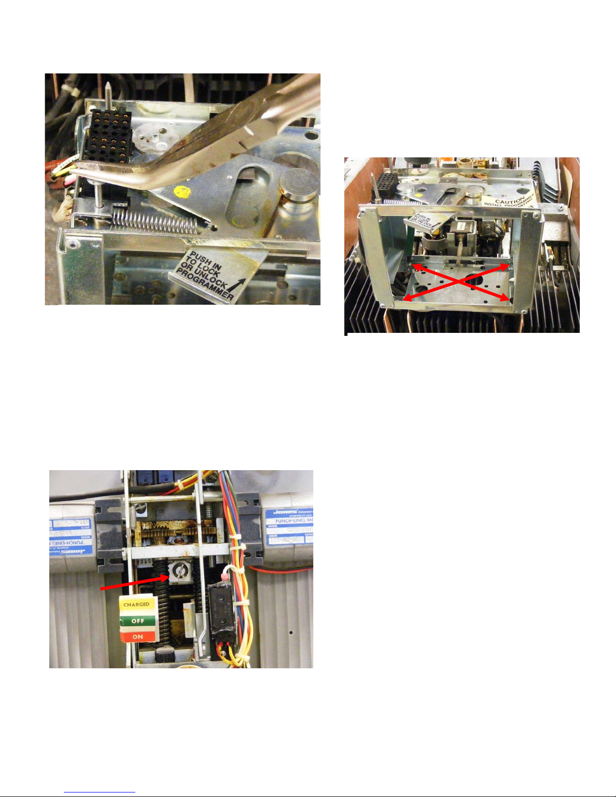
instructions. Conversion requires removal of
the original trip unit, installation of the new
trip device and minor rewiring. In the event
that any of the original components are found
to be defective, Satin American can provide
compatible replacements. Qualified
individuals can usually accomplish the
upgrade in less than an hour.
IMPORTANT!!
RETROFITTED BREAKERS MUST BE PERFORMANCE TESTED BEFORE BEING RETURNED
TO SERVICE. PRIMARY INJECTION TESTING IS STRONGLY RECOMMENDED. REFER TO
THE
TESTING
SECTION IN THE
SECTION II
MANUAL FOR DETAILED INSTRUCTIONS.
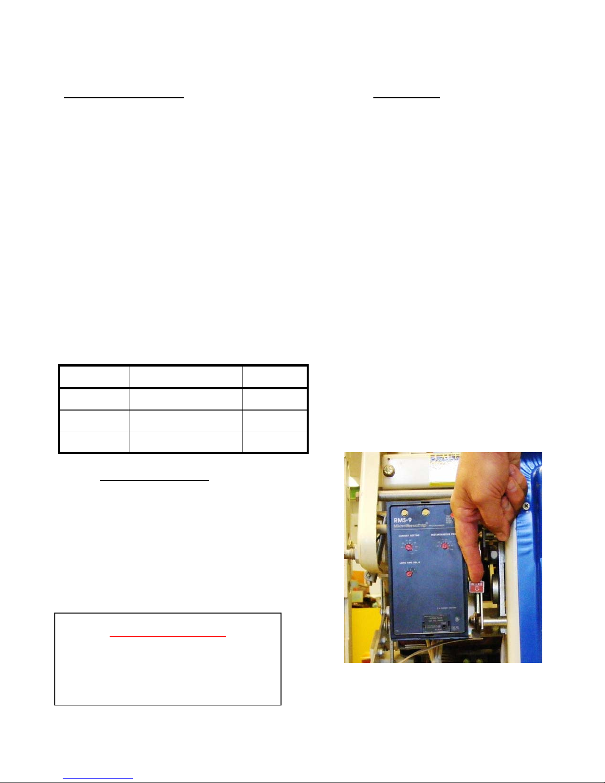
WARNING!!
TO PREVENT ELECTRICAL SHOCK AND INJURY, DISCONNECT THE BREAKER FROM ALL
PRIMARY AND SECONDARY POWER SOURCES AND CONFIRM THAT THE BREAKER IS
OPEN AND CHARGING SPRINGS ARE DISCHARGED BEFORE BEGINNING WORK.
REFER TO NFPA-70E FOR COMPREHENSIVE ELECTRICAL SAFETY
GUIDELINES

Instructions for use of etc-12/etd G Series Direct Replacement Trip Unit
page 5 of 13
revision B,
8/20/10
1.0 Required Tools:
1.1. Installation of this trip unit does not
require tools but since minor repairs and
adjustments are generally made at the same
time as the trip unit is upgraded, it is
recommended that a full set of basic hand
tools be available. When upgrading the trip
unit on breakers above 2000A, an included
jumper must be added to the existing wiring
harness. If this modification is required, it is
recommended that the pin extraction tool
listed in table 1 be available. This is because
it is not possible to remove and reposition the
jumper without the tool if it inserted
incorrectly in error. The table lists several
commercial sources of this tool. It can also
be obtained through Satin American.
Table 1
Sources for TYCO/AMP pin extraction tool #455822-2
Source Phone / URL Stock
Number
Allied
Electronics
(866) 433-5722
http://www.alliedelec.com/
527-0181
Digi-Key
Corporation
(800) 344-4539
http://www.digikey.com/
A9954-ND
Mouser
Electronics
(800) 346-6873
http://www.mouser.com/
571-4558222
2.0
Reference Material:
2.1. Manufacturers Circuit Breaker
Maintenance Manual.
3.0 Manual and time-current curves for
original trip unit.
3.1. etc-12 Section II Programmer
Instruction Manual
4.0
Installation:
4.1. Verify that the proper kit was supplied
and thoroughly inspect it for damage or
missing components.
4.2. Read and understand these
instructions before beginning the retrofit.
4.3. Place the breaker on a solid bench in
a clean work area were there is sufficient
access to all sides of the breaker.
4.4. Perform a detailed mechanical
inspection of the breaker. At a minimum,
verify that the breaker opens and closes
properly. Any mechanical problems should
be fixed prior to beginning the retrofit.
Normal maintenance can be performed prior
to or during kit installation.
4.5. Remove and existing solid state
tripping device by sliding the RELEASE
leaver on the existing programmer mount.
See figure 1. Before discarding original trip
unit, be sure to make note of settings.
IMPORTANT!!
BEFORE PROCEEDING, VERIFY
THAT THE BREAKER IS OPEN AND
CHARGING SPRINGS ARE
DISCHARGED
FIGURE 1, REMOVING EXISTING TRIP UNIT

Instructions for use of etc-12/etd G Series Direct Replacement Trip Unit
page 6 of 13
revision B,
8/20/10
4.6. Inspect existing wiring harness. The
etc-12 only requires wires connected to 10
locations on the harness connector. There
may be additional wires routed to this
connector. These additional wires should be
removed before installing the new trip unit.
Figure 2 indicates which positions in the
existing harness should be populated.
4.7. To remove a contact from the
connector, place the extraction tool into the
cavity from the front of the connector as
shown in figure 3. Press extraction tool
firmly into the connecter then depress the
plunger. Note that if the tool is not pressed
firmly into the connector before the plunger is
depressed, the contacts being extracted will
be damaged.
4.8. The jumper required for breaker
frames above but not including 2000A is
inserted in locations 35 and 36 of the
harness connector. These locations are
indicated in blue in figure 2. Location
numbers of each cavity are molded into the
rear of the connector but it is often possible
to install this jumper without removing the
programmer mount.
IMPORTANT!!
IF THE BREAKER FRAME SIZE IS
ABOVE (BUT NOT INCLUDING)
2000A, AN ADDITIONAL WIRING
JUMPER MUST BE ADDED AS
DETAILED IN STEPS 4.8 AND 4.9.
FAILURE TO INSTALL THIS JUMPER
CAN RESULT IN NUISANCE
TRIPPING
FIGURE 2,
PIN CONNECTIONS ON EXISTING HARNESS
LOCATIONS INDICATED YELLOW ARE
NECESSARY FOR PROPER OPERATION
LOCATIONS INDICATED IN GREEN ARE
REQUIRED ONLY IF A NEUTRAL CT IS UTILIZED
A JUMPER MUST BE PLACED IN THIS
LOCATION IF THE BREAKER IS LARGER THAN
2000A FRAME.
FIGURE 3, REMOVING UNNEEDED WIRES
FROM CONNECTOR

Instructions for use of etc-12/etd G Series Direct Replacement Trip Unit
page 7 of 13
revision B,
8/20/10
4.9. Figure 4 shows a rear view of the
existing mounting bracket with the supplied
jumper inserted. It is critically important that
the jumper snaps into place so that it cannot
be pulled out. When properly installed, the
contacts of the jumper should be flush with
the contacts already on the connector.
Figure 5 shows this connector not inserted
fully. Failure to fully jumper contacts can
result in nuisance trips.
4.10. Install the etc-12 G Series trip unit by
pulling down the RELEASE lever on the box
mount and inserting the brass retention pin
into the mating slot on the existing boxmount.
Pressing the retention pin against the flat
spring will cause the RELEASE lever to
move into the locked position. Refer to
figures 6 and 7.
4.11. Make certain that the new trip unit is
securely latched into place and its connector
is properly mated with the connector on the
box mount
FIGURE 4, REAR VIEW OF EXISTING BRACKET
SHOWING INSERTION OF JUMPER FOR FRAMES
GREATER THAN 2000A
JUMPER
FIGURE 5, CLOSE-UP VIEW OF CONNECTOR
SHOWING CONTACT NOT FULLY INSERTED
CONTACT IMPROPERLY
INSERTED
FIGURE 6, REAR VIEW SHOWING RETENTION PIN
FIGURE 7, NEW UNIT INSTALLED ON BREAKER
RETENTION PIN
SNAPS INTO
EXISTING LATCH

Instructions for use of etc-12/etd G Series Direct Replacement Trip Unit
page 8 of 13
revision B,
8/20/10
5.0
Installing on a PowerBreak
5.1. Remove trip unit bezel assembly by
removing the 4 screws indicated in figure 8.
5.2. Remove front cover by removing the 4
screws indicated in figures 9 and 10.
5.3. Remove the existing solid state trip
unit by pulling the release lever as indicated
in figure 12.
5.4. Inspect the wire harness and add
jumper if the breaker is above 2000A frame.
Refer to step 4.6.
FIGURE 9, REMOVE INDICATED SCREWS
FIGURE 11, REMOVE INDICATED SCREWS
FIGURE 10, REMOVE INDICATED SCREWS
FIGURE 12, Pull Lever to Release Existing Unit

Instructions for use of etc-12/etd G Series Direct Replacement Trip Unit
page 9 of 13
revision B,
8/20/10
5.5. Examine the back of the trip unit. If
the connector extends above the back plane
of the trip unit as shown in figure 13, the
mating connector must be repositioned as
detailed in steps 5.6 to 5.12If the connector
is flush, proceed directly to step 5.13
5.6. Remove the plastic connector housing
from the trip unit mounting bracket as shown
in figure 14. If necessary the metal tabs
retaining the plastic housing can be bent
slightly to allow the housing to be removed.
5.7. Slide the supplied “horseshoe”
adapter bracket over the plastic housing.
The notches in the plug body should fit
through the notches of the “horseshoe”.
Refer to figure 15.
5.8. After the plastic housing is properly
nested, the tabs on the horseshoe bracket
should be bent slightly as so to lock the
housing in place.
5.9. Slide the horseshoe bracket over the
positioning pins on the existing programmer
mounting bracket. Take care not to pinch
wires during this process. Secure horseshoe
in place with supplied push-nuts. See figure
16. Note: There may not be enough slack
left on the wiring harnesses on some
breakers. If this is the case, the programmer
mount must be removed as detailed in steps
5.10 through 5.12.
FIGURE 13, ORIGINAL TRIP UNIT WITH
CONNECTOR EXTENDING BEYOND THE BACK
PLANE OF THE UNIT
FIGURE 14, REMOVING THE CONNECTOR
HOUSING
FIGURE 15, HORSESHOE BRACKET INSTALLED
ON PLASTIC HOUSING

Instructions for use of etc-12/etd G Series Direct Replacement Trip Unit
page 10 of 13
revision B,
8/20/10
5.10. f there is not enough slack in the wire
harness, the existing programmer mount
may need to be removed in order for the
horseshoe bracket to be slid over the
positioning pins on the mounting bracket. To
remove the programmer mount, the front
mechanism of the breaker must be removed.
This is accomplished by loosening the screw
indicated in figure 17.
5.11. Carefully remove the front mechanism
from the breaker. When doing so, be
prepared to support both halves of the
breaker. Remove the existing box mount by
removing the 4 screws indicated in figure 18.
5.12. After the programmer mount is
removed, there should be enough slack in
the cable to slide the horseshoe over the
guide pins as described in step 5.9. Once
the horseshoe is secured in place, remount
the programmer mount and front mechanism.
5.13. Mount the etc-12 onto the existing
bracket by pulling the release lever and
sliding the guide pins into the holes in the
back of the trip unit. The brass retention pin
will mate with the existing mechanism on the
mounting bracket and lock into place. Make
certain that the connector on the programmer
is properly seated onto the mating connector
on the bracket. See figure 19.
FIGURE 16, SECURING HORSESHOE WITH
PUSH NUTS
FIGURE 17, LOOSEN INDICATED SCREW TO
REMOVE FRONT MECHANISM
FIGURE 18, REMOVE INDICATED SCREWS

Instructions for use of etc-12/etd G Series Direct Replacement Trip Unit
page 11 of 13
revision B,
8/20/10
5.14. Install the new escutcheon plate on
the trip unit bezel using the supplied 6-32 x
1/2 “ long flat head screw. See figure 20.
5.15. Replace the front cover of the breaker,
the trip unit bezel and install the Plexiglas
cover on the escutcheon.
FIGURE 19, etc-12 INSTALLED ON BRACKET
FIGURE 20, ESCUTCHEON PLATE

Instructions for use of etc-12/etd G Series Direct Replacement Trip Unit
page 12 of 13
revision B,
8/20/10
6.0
Settings
6.1. Trip settings must be determined by a
qualified engineer who has performed a
comprehensive study on the distribution
system where the breaker is to be used. The
etc-12 Section II manual provides detailed
instructions entering these settings into the
etc-12.
6.2. Table 2 lists the current sensor
secondary current rating for the current
sensors originally supplied with various
original trip units. In order to ensure proper
protection and prevent nuisance tripping, it is
important that this information be properly
entered into the etc-12 during set-up. Note
that the screens for selecting the 400 and
500mA will not be available unless the trip
unit is connected to the harness and the
jumper is installed per 4.8. The unit must be
completely powered down at the time it is
plugged into the jumpered harness or a self-
calibration error will occur. If the trip unit is
inadvertently plugged into the harness when
it is operating under battery power, it will
erroneously report phase currents when it is
not connected to a current source. This
problem can be remedied by powering down
the unit then re-powering it when it is already
connected to the jumper.
Table 2, CT Secondary Ratings
Original Trip Unit
Breaker Frame
Size
CT Secondary
Rating
RMS-9, RMS-9 Epic,
MicroVersaTrip,
MicroversaTrip Plus,
MicroVersaTrip PM
2000A and
below 200mA
RMS-9, RMS-9 Epic,
MicroVersaTrip,
MicroversaTrip Plus,
MicroVersaTrip PM
Above but
not
including
2000A
400mA
6.3. Table 3 provides a cross-reference of
the long-time delay bands on original GE
MicroVersaTrip units to the delays that are
available on the etc-12.
Table 3, Long-Time Delay
Cross-Reference
MicroVersaTrip
delay
Closest available
etc-12 delay
1
Custom, 3.5 sec @ 6L
2
Custom, 7 sec @ 6L
3
INT
4
MAX
6.4. Table 4 provides a cross-reference of
the short time delay bands on original GE
MicroVersaTrip units to the delays that are
available on the etc-12.
Table 4, Short-Time
Delay Cross-Reference
MicroVersaTrip
delay
Closest available
etc-12 delay
MIN
.150 seconds
INT
.300 seconds
MAX
.400 seconds
6.5. Table 5 provides a cross-reference of
the ground fault delay bands on original GE
MicroVersaTrip units to the delays that are
available on the etc-12.
Warning!
This retrofit kit was not designed to
increase the current rating of the circuit
breaker. Do not operate the breaker
above the manufacturer’s maximum
ampere rating. Failure to adhere to this
warning will result in damage to, failure
of, or shortened circuit breaker life
expectancy.

Instructions for use of etc-12/etd G Series Direct Replacement Trip Unit
page 13 of 13
revision B,
8/20/10
Table 5, Ground-Fault
Delay Cross-Reference
MicroVersaTrip
delay
Closest available
etc-12 delay
MIN
.150 seconds
INT
.300 seconds
MAX
.400 seconds
7.0
Testing
7.1. Conduct a full performance test of the
trip unit and breaker. Primary injection
is strongly
recommended for newly retrofitted
breakers. Refer to the etc-12 Section II
manual for detailed test procedures and
specifications.
NOTE: MicroVersaTrip, MicroVersaTrip Epic,
MicroVersaTrip RMS-9, MicroVersaTrip Plus and
MicroVersaTrip PM are products of General Electric.

Table of contents
Popular Other manuals by other brands

HAKO
HAKO Cleanserv C34 instruction manual

Thetford
Thetford C-200 CS D3 installation instructions

Sharper Image
Sharper Image SHP921 manual

BOERBOEL
BOERBOEL Heavy Duty 8" Double Strap Hinge installation instructions

Pittsburgh Automotive
Pittsburgh Automotive 64982 Owner's manual & safety instructions

Delton
Delton BERTA Technical installation manual