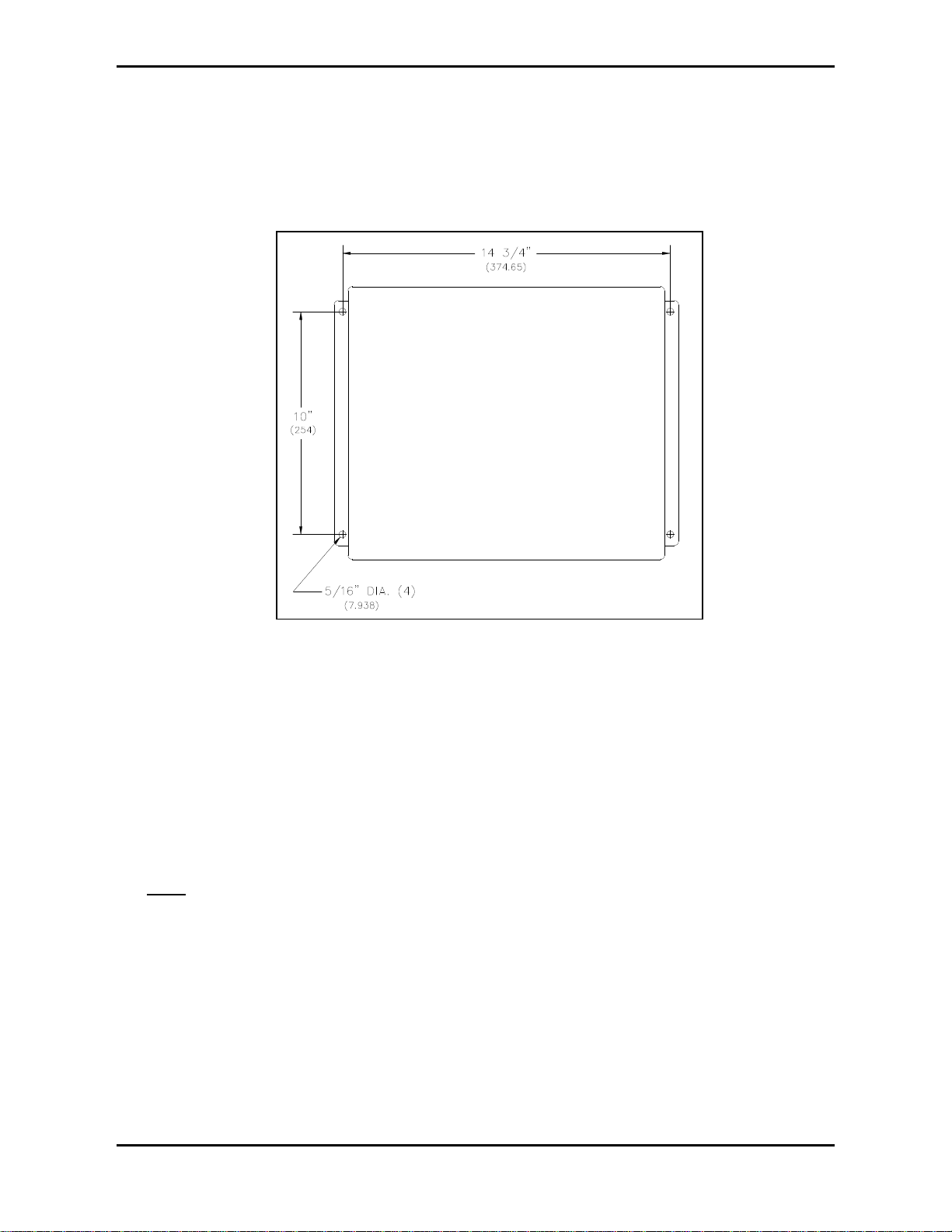
GAI-Tronics 1931888-3011 User manual

Pub. 42004-245A
GAI-Tronics Corporation P.O. Box 1060, Reading, PA 19607-1060 USA
610-777-1374 n800-492-1212 nFax: 610-775-6540
GAI-TRONICS CORPORATION
Model 1931888-3011
Page/Party®to Radio Coupler
Confidentiality Notice
This manual is provided solely as an operational, installation, and maintenance guide and contains
sensitive business and technical information which is confidential and proprietary to GAI-Tronics. GAI-
Tronics retains all intellectual property and other rights in or to the information contained herein, and
such information may only be used in connection with the operation of your GAI-Tronics product or
system. This manual may not be disclosed in any form, in whole or in part, directly or indirectly, to any
third party.
Introduction
The Model 1931888-3011 Coupler, when connected to a GAI-Tronics Two Channel Radio, allows a
GAI-Tronics Page/Party®or Call/Talk system to communicate with other Two Channel Radio hand-held
or mobile units. Radio users traveling outside the facility at a remote location or inside a plant, can
communicate with Page/Party®or Call/Talk users. Please see Figure 1for installation layouts.
Installation and Wiring
Punch or drill a hole in the left side or left bottom of the coupler and install a conduit fitting. This entry
is for system cable from the Page/Party®or Call/Talk system to the coupler. Sealed threaded hubs, such
as Myers Scru-Tite (1.25-inch) are recommended.
Figure 1. Installation Layout

Page: 2of 10
Model 1931888-3011 Page/Party®to Radio Coupler Pub. 42004-245A
f:\standard ioms - current release\instr. manuals (42004)\42004-245a.doc
01/98
Since the Model 1931888-3011 coupler must be connected to a Two Channel Radio, mount the coupler
and radio in a place where the antenna for the radio may be appropriately positioned. See the Two
Channel Radio manual, GAI-Tronics publication 42004-252 for antenna placement information.
The coupler should be wall-mounted using the four 5/16-inch (7.938 mm) mounting holes. See Figure 2
for dimensions.
Use GAI-Tronics 60038-101 system cable to connect the closest Page/Party®or Call/Talk station to the
coupler:
1. Connect the 120 V ac power conductors, black, white, and green with yellow, from the Page/Party®or
Call/Talk station to TB-1, TB-2, and TB-5 respectively in the coupler.
2. Use the red with blue and blue with red twisted pair to connect the page line L1 and L2 in the station
to TB-3 and TB-4 respectively.
3. Use the red and tan with red twisted pair to connect party line 5 (or designated party line) L1 and L2
from the station to TB-7 and TB-8 respectively.
Note: Party line 5 is used here for explanation purposes.
4. TB-6, and TB-9 through TB-14 are factory connections.
Figure 3and Figure 4show the terminal blocks in the Page/Party®and Call/Talk stations, respectively, as
well as the 14-lug terminal block in the coupler. Cables with three-prong and four-prong military style
MS connectors are included with the coupler. These cables connect from the bottom of the coupler to the
top of the radio.
Figure 2. Mounting Details

Page: 3of 10
Model 1931888-3011 Page/Party®to Radio Coupler Pub. 42004-245A
f:\standard ioms - current release\instr. manuals (42004)\42004-245a.doc
01/98
Figure 3. Wiring/Termination Details for Page/Party®

Page: 4of 10
Model 1931888-3011 Page/Party®to Radio Coupler Pub. 42004-245A
f:\standard ioms - current release\instr. manuals (42004)\42004-245a.doc
01/98
Figure 4. Wiring/Terminations for Call/Talk

Page: 5of 10
Model 1931888-3011 Page/Party®to Radio Coupler Pub. 42004-245A
f:\standard ioms - current release\instr. manuals (42004)\42004-245a.doc
01/98
Modification of Two Channel Radio Unit for use with Coupler
In order to be used with the Model 1931888-3011 coupler, the Two Channel Radio must be modified by
relocating jumper, J2 from the factory setting. J2 is located on the main motherboard WBA4448SYNxx
inside the radio unit. Perform the following steps to make the modification:
1. Remove all cables from the radio.
2. Remove the 4 screws securing the front cover.
3. The 3-pin connector, J2 is located to the left and adjacent to TB1. Use small needle-nose pliers to
move the shorting jumper from position 1-2 to 2-3.
4. Reinstall the cover to the unit.
5. Reconnect the cables.
Operation
The Model 1931888-3011 Coupler connects one radio frequency (channel) to one party line in the
Page/Party®or Call/Talk system, usually party line 5. When a remote radio is not in use, the coupler
monitors party line 5.
In order for a Page/Party®or Call/Talk user to contact a radio user, the caller must go off-hook on party
line 5. The resulting communication is simplex. This means that the radio user controls the flow of the
conversation with the push-to-talk, release-to-listen mechanism of the radio.
Call Originated by a Page/Party®or Call/Talk User to a Radio User:
Audio Path from Page/Party®to Radio:
The caller from a Page/Party®, Call/Talk or U/A station goes off-hook on the designated party line. This
causes the station’s output transformer to load the line (loop current on the line begins) at the Model
1931888-3011 coupler’s TB-7 and 8 and is detected by the Model WBA2757 Sensing PCBA inside the
coupler. The following relay functions occur:
1. The sensing PCBA detects the off-hook condition on the party line and activates the XFR relay and
illuminates LED 3.
2. The XFR (transfer) relay is activated by the sensing PCBA. It transfers the audio path from the
‘Radio-Page’ line to the ‘Radio-Party’ line.
3. The VOX board detects audio from the system party line. When sufficient system party line audio is
present, it activates VX1 relay and illuminates LED 1.
4. VX1 (VOX) relay toggle operation is activated by the Voice Operated Switch (VOX) PCBA. While
the relay is activated:
•It provides the audio connection path from the party line to the radio’s microphone-in circuit
(TB-12 and 13) via the coupler’s RADIO VOL control (VC1).
•It disables SQ1 (squelch) relay during party line talk mode for uninterrupted communication.
•It provides a contact closure at TB-11 to ground to key the radio transmitter circuitry.

Page: 6of 10
Model 1931888-3011 Page/Party®to Radio Coupler Pub. 42004-245A
f:\standard ioms - current release\instr. manuals (42004)\42004-245a.doc
01/98
Audio Path from Radio to Page/Party®:
1. After the Page/Party®caller has finished talking, the radio user answers the call by simply keying the
microphone and talking.
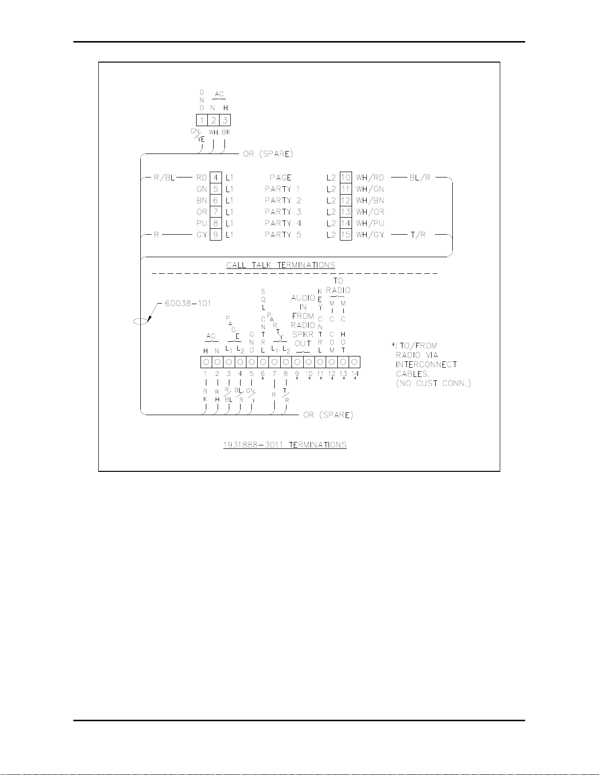
2. When the coupler’s radio receives the signal, the audio signal appears at the coupler’s TB-9 and 10
via the 3-wire interconnect cable assembly. Squelch control is also provided from the radio to the
coupler’s TB-6 via the same interconnect cable.
3. With the squelch control present, the following relay functions occur:
•SQ1 (squelch) relay is activated by SQUELCH control from the radio and illuminates LED 2.
This provides the audio connection path from ‘Radio-Party’ line via the UA VOL control
(VC2), and disables VX1 relay for uninterrupted party communications from the radio.
•XFR (transfer) relay stays active to maintain the audio path from the radio to the Page/Party®
system’s party line.
•VX1 (VOX) relay is disabled by SQ1 relay for uninterrupted party communications from the
radio.
The signal path continues in this manner until both parties have completed their conversation.
Call Originated by Radio User to Page/Party or Call/Talk System Page Line:
Audio path from radio to Page/Party®:
1. The radio user makes a call by simply keying the microphone and talking (push-to-talk/release-to-
listen) after first insuring that the channel is clear.
2. When the coupler’s radio receives the signal, the audio signal will appear at the coupler’s TB-9 and
10. Also, the SQUELCH control signal is provided from the radio at TB-6 via 3-wire interconnect
cable assembly.
3. With SQUELCH control signal present, the following relay functions occur:
•XFR (transfer) relay is inactive (no party line loop current is present [Page/Party®stations on-
hook]) and LED 3 is off. This results in maintaining the audio path from the radio to the
Page/Party® system’s page line.
•SQ1 (squelch) relay is activated by SQUELCH control signal from radio and illuminates
LED 2. This provides the audio connection path from ‘Radio-Page’ line (page line TB-3 and
4) via the UA VOL control (VC2), and disables VX1 relay for uninterrupted communications
from radio to the Page/Party®system’s paging speakers.
•VX1 (VOX) relay is disabled by SQ1 relay.
Audio path from Page/Party® to radio:
The called party goes to a Page/Party®station, selects the dedicated party line, and goes off-hook. This
causes the Page/Party®station’s output transformer to load the line (loop current on the line begins) at the
Model 1931888-3011 Coupler’s TB-7 and 8 and is detected by the sensing PCBA within the coupler. For
a continued explanation of the subsequent events, refer to the Call Originated by Page/Party®or Call/Talk
User to Radio section.

Page: 7of 10
Model 1931888-3011 Page/Party®to Radio Coupler Pub. 42004-245A
f:\standard ioms - current release\instr. manuals (42004)\42004-245a.doc
01/98
Time Out Timers
The coupler is equipped with two 2 timer boards labeled TMR #1 and TMR #2. The function of the
boards are provided to limit the transmission times of both the system and radio.
TMR #1
The TMR #1 board is controlled by the VOX board during party line communication from the
Page/Party®system to the radio. When VOX control signal is present at TMR #1’s pin 1 (system talk
mode), the output at pin 2 is pulled low to activate the VX1 relay. When party line audio is no longer
present on the line, the VOX output is removed and the VX1 relay drops-out to permit radio response.
However, if the station remains off-hook on the party line and noise levels occur, the VOX will detect the
levels on the line, and key the radio. Under this condition, the timer board will time-out and disable the
VX1 relay to remove radio keying control after approximately one minute.
TMR #2
The TMR #2 board is controlled by SQUELCH control from the radio to Page/Party®system’s party line
communications. When the SQUELCH control signal is present at TMR #2’s pin 3 (radio talk mode), the
output at pin 2 is pulled low to activate the SQ1 relay.
When radio SQUELCH control and audio is no longer present, the SQ1 relay drops-out to permit system
response. However, if the radio remains in receive mode with SQUELCH control, party line audio cannot
be transmitted back to the radio system. Under this condition, the timer board will time-out and disable
the SQ1 relay to remove radio SQUELCH control after approximately one minute.
Maintenance
Control Functions:
The Model 1931888-3011 Coupler contains four adjustment controls which have been pre-adjusted at the
factory. Minor adjustments may be necessary for optimum system performance. Refer to Figure 5.
Control Description:
•UA VOL: Adjusts the audio level being coupled to the Page/Party® or Call/Talk system from
the radio’s speaker out. Clockwise rotation of the control increases the audio drive level.
•RADIO VOL: Adjusts the audio level being coupled to the radio’s microphone-in circuitry
from the Page/Party® or Call/Talk system. Clockwise rotation of the control increases the
audio drive level.
•VOX SENS: Adjusts the threshold level (activation point] for the Voice Operated X switch
circuitry to activate. Clockwise rotation of the control increases the sensitivity level.
•TRANSFER SENS: Adjusts the threshold level for the TRANSFER detection circuitry to
activate. Clockwise rotation of the control increases the threshold level for XFR relay
activation when an associated Page/Party® station is off-hook.

Page: 8of 10
Model 1931888-3011 Page/Party®to Radio Coupler Pub. 42004-245A
f:\standard ioms - current release\instr. manuals (42004)\42004-245a.doc
01/98
Typical audio signal levels within coupler from Page/Party® station to coupler:
With approximately 1.5 Vrms on Page/Party® system party line (TB-7 and 8); with an associated
Page/Party® station off-hook:
Audio signal at TB-12(com) and 13; Mic In = approximately 0.45 Vrms, nominal
(Radio Vol. Min/Max range = 0 V / 1.24 Vrms)
Typical audio signal levels from coupler to Page/Party® station:
•With approximately 10 Vrms of received speaker audio at TB-9 and 10; with XFR relay’s LED 3
NOT illuminated and all associated Page/Party® stations on-hook:
Audio signal at TB-3 and 4 (page line) = 0.5 Vrms** nominal.
(UA Vol. Min/Max range = 0 V / 3.0 Vrms**)
•With approximately 10 Vrms of received speaker audio at TB 9 and 10; with XFR relay’s LED 3
illuminated and an associated Page/Party® station off-hook:
Audio signal at TB-7 and 8 (party line) = 0.5 Vrms** nominal.
(UA Vol. Min/Max range = 0 V / 3.0 Vrms**)
**Voltages indicated are typical with indicated signal levels, actual voltages measured may vary with
different audio drive levels.
Figure 5. Part Location Diagram

Page: 9of 10
Model 1931888-3011 Page/Party®to Radio Coupler Pub. 42004-245A
f:\standard ioms - current release\instr. manuals (42004)\42004-245a.doc
01/98
Troubleshooting
Symptom/Possible Solutions
Symptom: Visual LED
Indication: Cure:
The radio operator can not
make a page to the
Page/Party® or Call/Talk
system’s paging speakers,
but can communicate on
designated party line.
XFR relay LED is
illuminated. 1. Check for possible off-hook Page/Party®
stations and/or low resistance on the
designated party line and correct as
necessary.
2. Check adjustment of “TRANSFER SENS”
pot. Factory setting = approx. ¼ turn CW
from minimum. (Fully CCW)
Page/Party® system user
has low modulation audio
to radio operator.
N/A 1. Check adjustment of RADIO VOL. pot.
readjust as necessary.
Factory setting = approximately mid range.
2. Check for proper jumper location of J2
inside the associated radio unit.
[For coupler operation, J2 must be in Pos. 2 and
3 versus Pos.1 and 2 (factory setting)]
While Page/Party® station
is off-hook, the associated
coupler’s XFR relay
activates ,but VX1 relay
does NOT activate when
speaking into handset.
XFR relay LED is
illuminated and VX1
relay LED is NOT
illuminated.
1. Check adjustment of “VOX SENS” pot.
(Factory setting = approx. ¼ turn CW from
minimum. (Fully CCW)
2. Check for defective VOX PCB assembly.
Replace WBA4417, if necessary.
No communications in
either direction. No relay LEDs are lit in
any mode. 1. Check for proper ac supply voltage to
coupler at TB-1 and 2.
2. Check FU1. Replace, if necessary, with
fuse of the same value and rating.
3. Check CO1B power supply. Replace, if
necessary.
4. Check external wiring connections.
If SQ1 relay LED is
NOT illuminated:
1. Check CC1 module. Replace WBA4259, if
necessary.
2. Check speaker cable assembly (3-wire
connector) connections.
No communication from
radio operator to
Page/Party® station is
possible, but
communications from
Page/Party® station to
radio operator are OK. If SQ1 relay LED IS
illuminated: 1. Replace SQ1 relay.
2. Check external page connections to
Page/Party® system.

Page: 10 of 10
Model 1931888-3011 Page/Party®to Radio Coupler Pub. 42004-245A
f:\standard ioms - current release\instr. manuals (42004)\42004-245a.doc
01/98
Specifications
Construction/Finish: ..... ................................16-gauge steel, oil resistant gasket, ANSI #61 gray polyester
coating, NEMA-12 rated
Mounting:..................... ..........Four 5/16-inch (7.9mm) mounting holes, center to center measurements of
14.75 x 10 inches L x H (374.65 x 254 mm)
Dimensions:.................. ....................................14 x 12 x 6 inches L x W x D (354.0 x 304.8 x 152.4 mm)
Shipping Weight:.......... .....................................................................................................28 lb. (12.72 kg)
Power Requirements:.... .........................................Voltage: 108-132 V ac (50/60 Hz), 120 V ac, nominal
..................................... ......................................................................... Power Consumed: 24 VA, 9 watts
REPLACEMENT PARTS (Refer to Figure 5 for locations)
Item # Part Number Description
124870-006 LED, Red T-1
243276A-7011 Cable Assembly, Microphone
343276A-7012 Cable Assembly, Speaker
4C01B PCBA, Power Supply
5 WBA4417 PCBA, VOX Board Assembly
6 WBA4259 Module, Squelch Control (CC1)
7 05839 Relay
851812-001 Fuse 2 amp, 125 V
Table of contents
Other GAI-Tronics Telephone System manuals