3. 18VAC appears at TBC as described in sec-
tion 5.2d, if required for customer provided
buzzer signaling. Refer toCD-0423-000for more
details.
MUSIC-ON-HOLDINSTALLATION
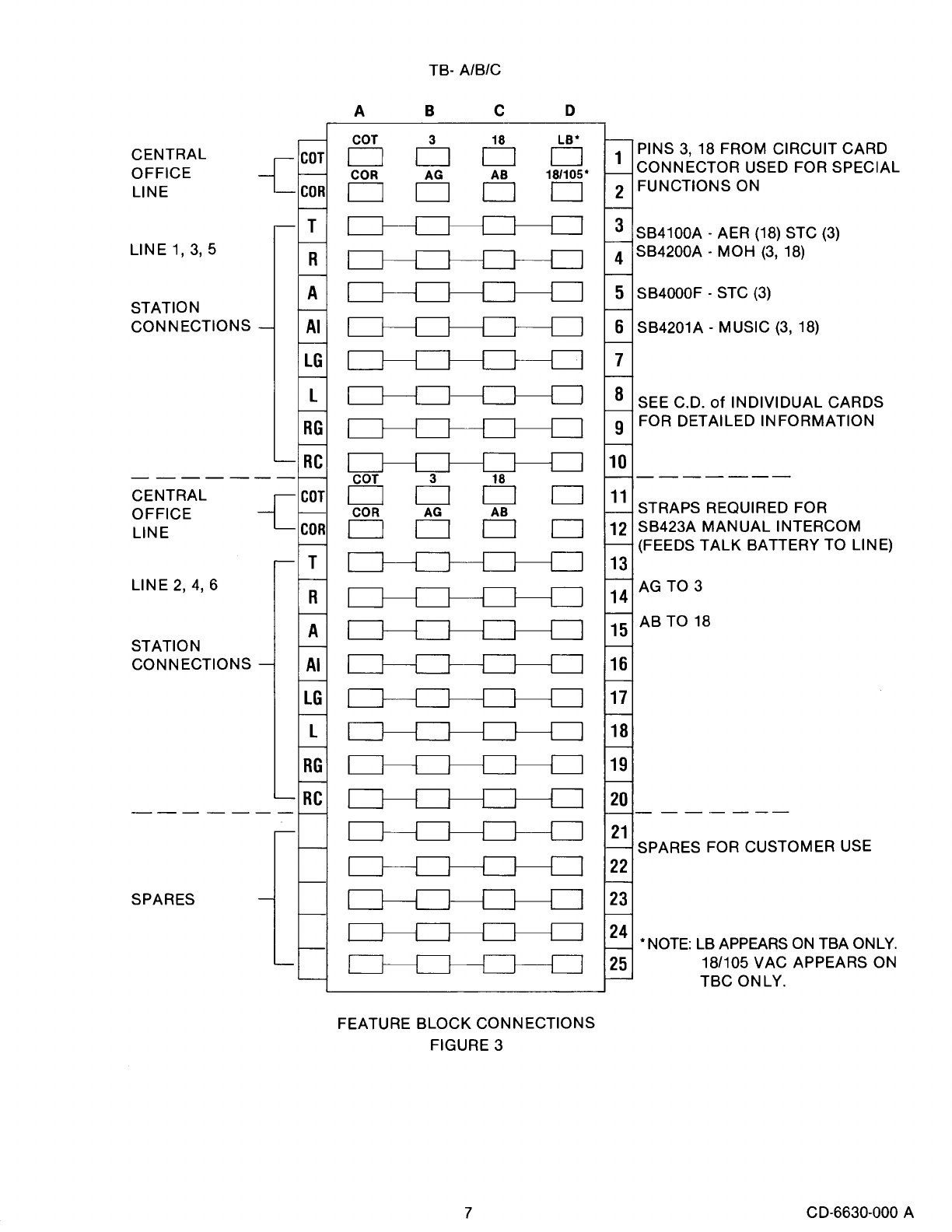
a. SB4200A Line Cards
The SB4200Acards may be installedinposition
1 thru 6. The music source is distributed via
pins3and 18. Jumpertogetherallpin3's and all
pin 18's at the appropriate feature block posi-
tions involved.
Connect the music source (if externally provid-
ed toany of the pins3and 18terminals. Referto
CD-4200-000for more details.
b. SB4201
FM
Receiver
If using the SB4201A, install in any spare posi-
tion 1thru 6. Jumper (at the feature block) pins
3and 18tothe rest of the music distribution as
described above. Externalantennaconnections
are brought into the feature block to T, R.
NOTE: If usingAE line cards for music-on-hold,
connect together allthepin3's of each position
including the SB4201A. Leave pin 18 open at
each line position. Jumper AG to 18 at the
SB4201A position.
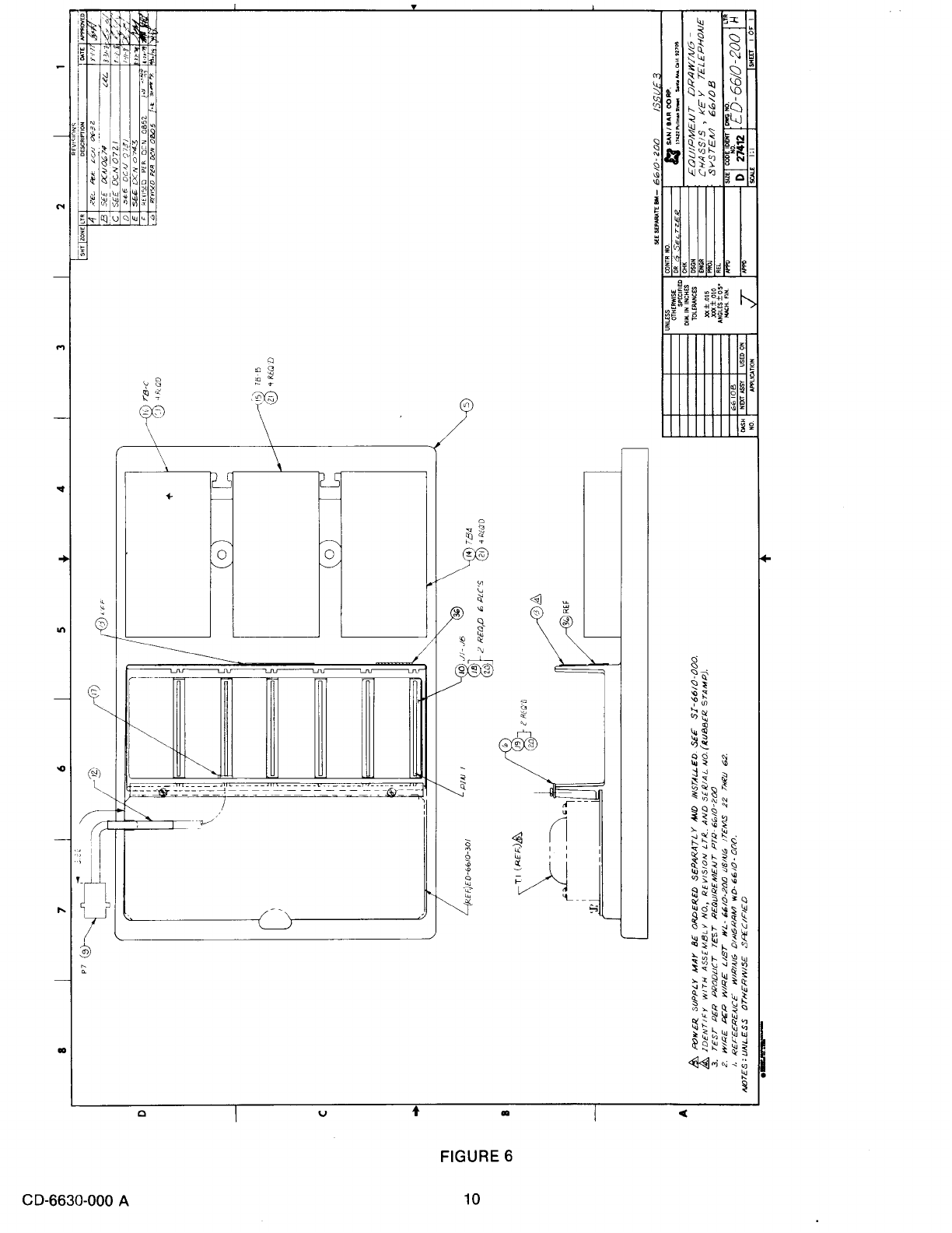
Cover Mounting
The cover for the KTSsecures tothe chassis by
snap-intabs. The cover does not require any ad-
ditional clearance from the ceiling or adjacent
equipment. To mount the cover, first insert the
two top mounting tabs. Secure the cover by in-
serting the two lower (outside) tabs and then
snapping the locking tab (lower-middle) into
place. To remove, press up on the locking tab
and the cover will come off easily.
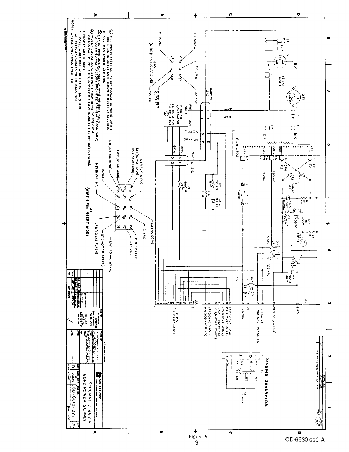
CIRCUIT DESCRIPTION
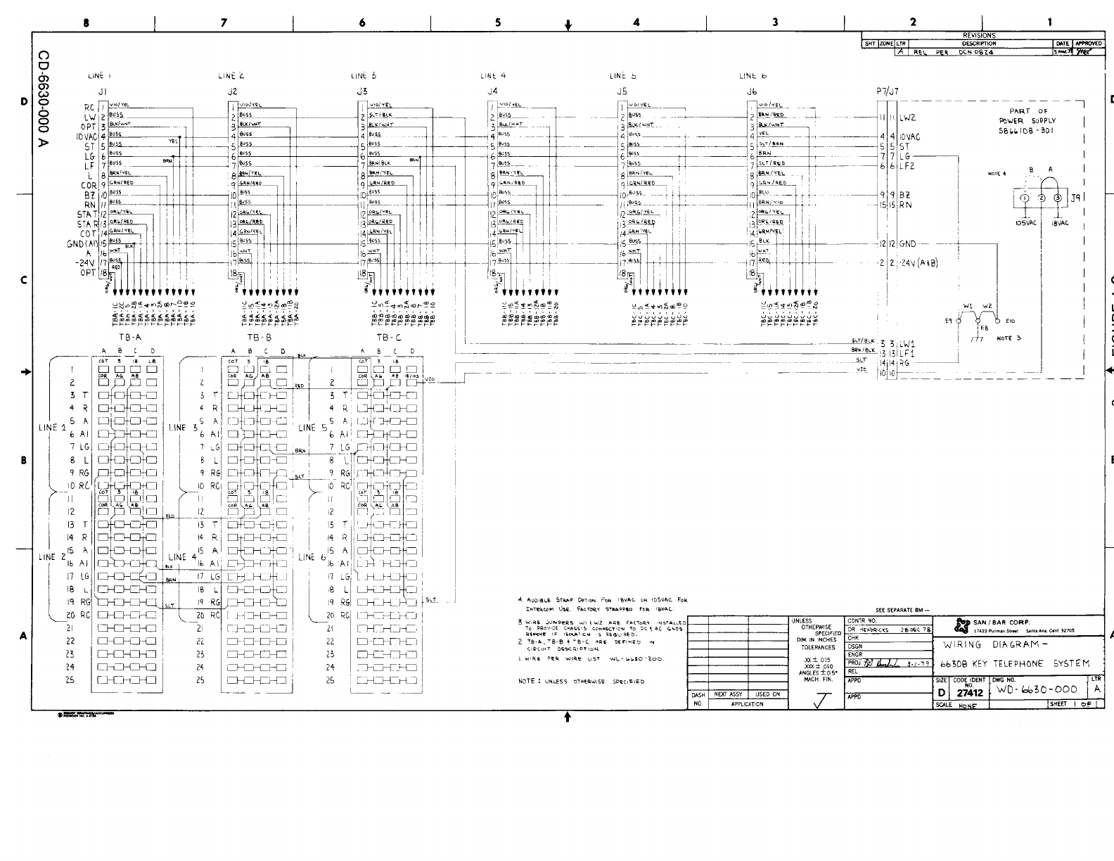
Please refer tothe schematic drawings Figures
4
&
5
for the following descriptions.
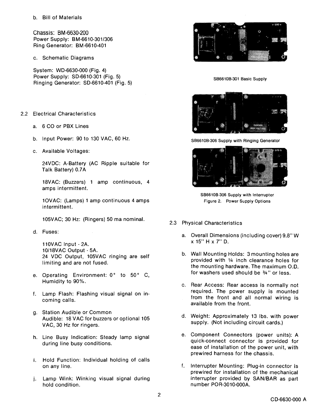
SB6610B Power Supply
117VAC isapplied to the primary winding (Blk-
Blk)of transformer TI.The transformer has two
secondary windings. One winding istapped to
provide
10
and
18
VAC
which provides the lamp
and buzzer output voltages. The other winding
has an output of 32 VAC which isfull-wave rec-
tified by diode bridge CR1-CR4 to produce
5
4OVDC across capacitor C1. Transistors Q1 and
Q2, together with Zener diode CR5, form a pre-
regulator which keepsaconstant 30VDCacross
the input of VR1. VR1 is an integrated voltage
regulator which maintains a constant 24VDC at
its output. VR1 is internally current limited, so
no output fusing is necessary.
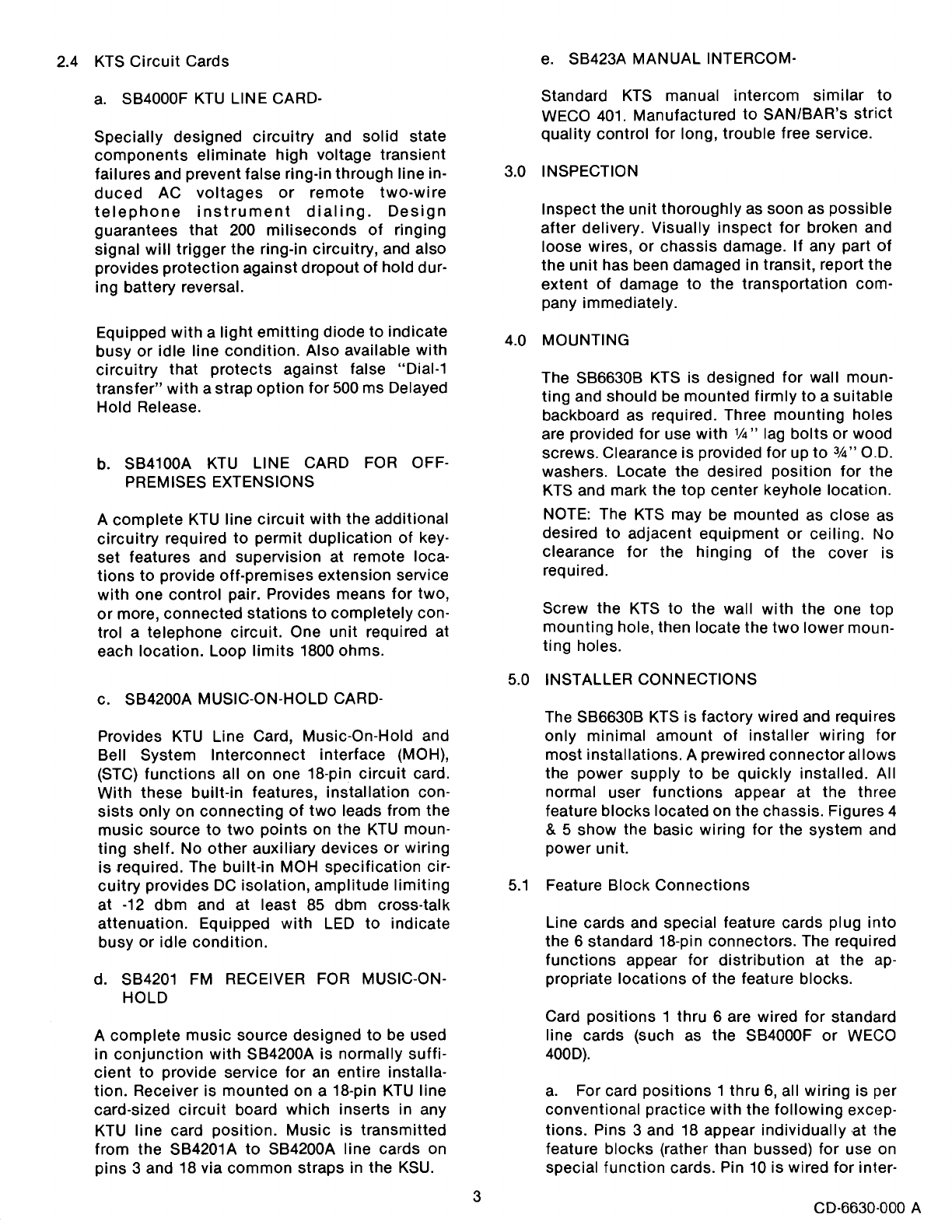
SB6610B-401Ringing Generator
AC linevoltage appears acrossthesplit primary
windings and associated network of T2.
Because of the diode CR1, much more current
flows in one direction than the other, causing
the secondary voltage to have a heavy 30 Hz
component. Capacitor C1 and the secondary
winding are resonant at 30 Hz, so that the out-
put voltage across T2-4 and T2-3 will be an ap-
proximate sine wave, with a fundamental fre-
quency of 30
Hz.
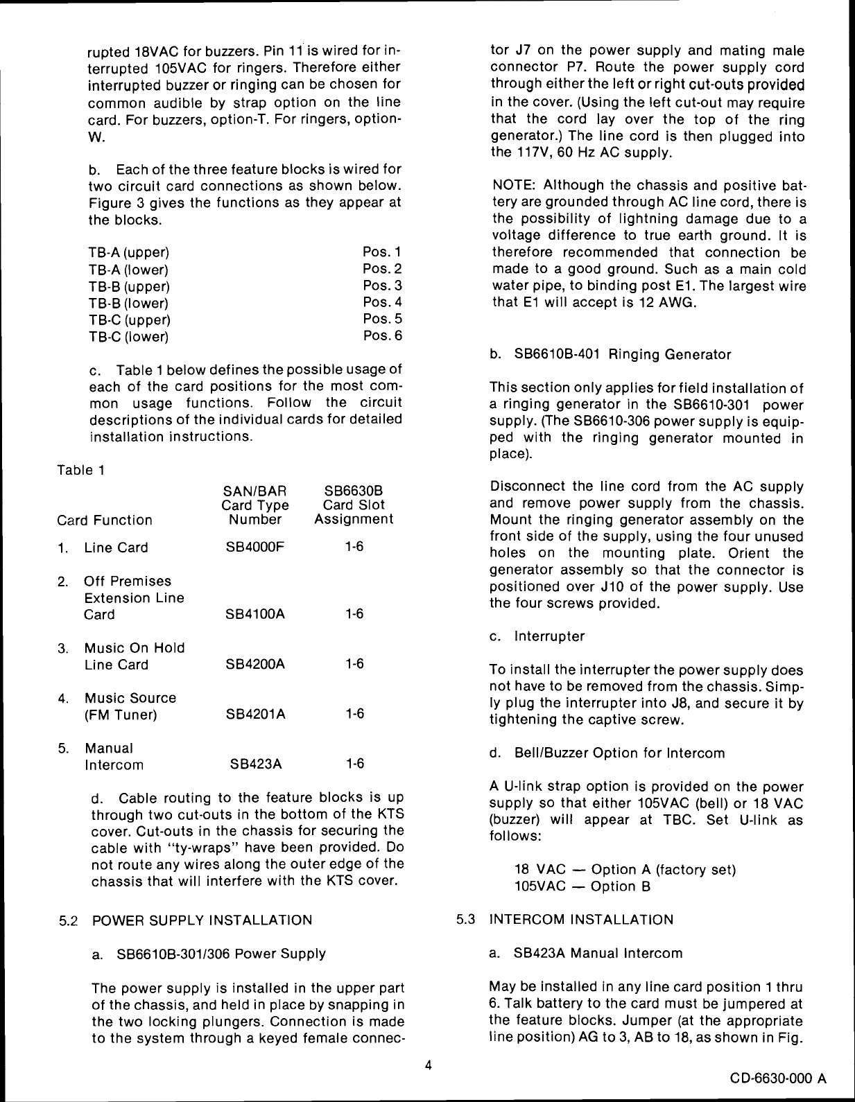
Interrupter
When AC common is applied to the interrupter
on the ST lead, the motor will run. IOVAC,
18VAC and 105VAC are interrupted by cam-
driven contacts to provide Lamp Wink, Lamp
Flash, Interrupted Buzzerand Ringingvoltages.
TESTING
Key Telephone System
Iftrouble isencountered with the SB6630B Key
Telephone System, check that all installer con-
nections or strap options have been made pro-
perly. Refer to the individual circuit card
descriptions for test of the units. The KTS fix-
ture contains noelectrical components that are
normally considered subject to failure.
However, possible wire breakage or poor wire
terminations may be verified using normal con-
tinuity checking procedures with a standard
multimeter (Simpson 263 or equivalent).
Power Supply Assembly
If the system difficulties is determined to be
related to the power unit, make sure that the
system power requirements have not exceeded
the powersupply ratingspecified insection 2.0.
Make sure that the installer connections are
made properly. Verify that the connector is
mating properly. If trouble persists, verify that
all powersupply voltage outputs are present us-
ing a standard multimeter. Refer to the
schematic diagrams for locatingwhere the out-
puts appear. (NOTE: It may be necessary to
removethe power supply from the KTS toverify
the problem if itisdue to shorts
in
the system).