Gainsborough TALANO User manual

Talano & Alera Installation v2.6 2
Installation
Access
When deciding on a suitable location to install the bath, there are a number of points that should be
taken into consideration:
•Hoist/wheelchair access.
•Service/cleaning access.
•Positions of any existing under floor pipe work or cabling.
•Conflict between doorways.
•Distance from walls/other objects.
•Under-floor obstructions (water/heating pipes, waste pipes, under-floor heating).
•Level flooring.
IMPORTANT –The bath must be sited on a level and sound floor against straight walls.
Flooring
Prepare the floor area for installation. Please ensure that the flooring is flat, level and structurally
sound. There should be no services or underfloor heating buried within the ‘Foot Plate’ area
detailed on Figure 1.0. All floor finishes should be in place prior to installation (i.e. Altro / Tiling).
Items supplied with the Bath:
•Installation manual
•User manual
•Bath unit (bath shell, support frame, control pack)
•Bath surround panels
•User handset
•Foot base unit fixing kit (comprising bolts/screws - see floor fixing kit)
Preparation
a) Carefully remove all packaging and inspect the bath thoroughly.
Note: Do not use sharp knives or instruments to remove packaging around the finished surface
areas of the bath.
b) Ensure all component parts are present before beginning installation.
It is important to ensure the complete kit is there. If there are ANY components missing contact the
service department and quote the number on the side of the bath.
c) Prepare the floor area and ensure it is flat, level and structurally sound and that there are NO
SERVICES BURIED within the floor fixing area.
Bath Moving
IMPORTANT –Do not move the bath by the bath shell. Only use the metal support legs.

Talano & Alera Installation v2.6 3
Quick Sequence Overview
•Check site position. Ensure all Pre-install requirements have been met.
•Inspect bath and panels for damage. Clear area and make sure floor is level and clean.
•Manoeuvre the bath into its intended position.
•Remove transport wheels from bath if fitted.
•Leave transport tie bars in place if fitted. Set the foot base plate distances to correct dimensions.
•Mark the position of the floor fixing holes. Move the bath to allow the drilling of the holes
•Clean out dust and debris from holes.
•Fix bath to floor. Feet frames MUST be level and vertical. Use a spirit level. Utilise shims if
required.
•Connect bath to temporary power supply. Connect handset and power up bath.
•Place bath into position. Connect plumbing to bath connections.
•Connect waste.
•Make a permanent electrical connection and secure cable using conduit if required.
•Fasten Chrome handset holder into place. Fit handset connector socket to front panel.
•Fit front panel. Slide panel under lip of bath. Fix to floor batten.
•Fit end panel(s). Slide panel under lip of bath. Fix to floor batten as required.
•Check for leaks and operation. Check temperature set up on the TMV control(s)
•Attach SWL and labels as required.
•Fully test sequence
Figure 1.0
Tap End
of Bath
Foot Base
Plate Bath
Frame

Talano & Alera Installation v2.6 4
Talano 1700/1500 Key Information
Maximum User Weight : 165Kg; Transfer Seat 140kg.
Maximum Water Capacity : 230/200 litres
Approximate Bath Weight (Empty) : 119Kg/115Kg.
Power Supply : Mains 230V to be supplied via 30mA RCD.
Operating Voltage : 24V
Battery Backup : Yes.
Water Supply : Hot & Cold water at 1 bar minimum.
RIGHT HAND SHOWN (Diagram shows fixed seat with hoist access panels.)
Fixed Seat Height 460mm
Transfer Seat Height 500mm
Figure 2.0

Talano & Alera Installation v2.6 5
Alera 1700/1500 Key Information
Maximum User Weight : 165Kg; Maximum Water Capacity : 230/200 litres
Approximate Bath Weight (Empty) :130Kg/125Kg.
Power Supply : Mains 230V to be supplied via 30mA RCD.
Operating Voltage : 24V
Battery Backup : Yes.
Water Supply : Hot & Cold water at 1 bar minimum
RIGHT HAND SHOWN (Diagram shows fixed seat with hoist access panels.)
Figure 3.0

Talano & Alera Installation v2.6 6
Fitting Instructions
Prior to installation, ensure that the site is prepared in accordance with the requirements detailed in
the Pre-Installation manual. Inspect the installation area, paying particular attention to floor fixing
locations. Ensure that the flooring is of a sound, solid surface with no movement or flex, and is clear
from dirt and debris.
1) Move the bath into the local area. There are 4 transport wheels –one in each corner. Remove
the wheels and attach the adjustable bath feet (supplied) to the tap end of the bath. It is essential to
keep the foot frames at the correct spacing (see figure 4.0 for further details).
2) Offer the bath into position making sure that the floor is of a sound, solid surface. If the floor
slopes, (i.e. wet room installation with a centre drain) shims should be fitted under the bath feet or
foot plate making sure that the fixings hold the feet firmly in place. The most common issue with
bath failure is the bath not being fitted level and firmly to the floor.
3) Set the foot frames. Ensure that the space between the feet and base plate is set correctly (see
figure 4.1 for dimensional information). The foot base plate must be vertical and upright. Adjust the
height of the feet at the ‘tap end’ of the bath to ensure bath is level in all aspects. Floor finish, (i.e.
Altro / Tiling etc.) must be in place prior to installation.
Figure 4.1
1700 bath Right Hand 1500 bath Right Hand

Talano & Alera Installation v2.6 7
Fitting Instructions
Figure 5.2
Imperative base plate fixing locations. Note - Sleeves will not grip unless the hole is cleaned out first. Table
details fixings for foot plate end of bath. Ensure washer is placed between Fischer screw head and foot plate to
protect the painted surface.
Seat
post
Head end of bath –Right Hand Shown
IMPERATIVE - A
IMPERATIVE - B
Figure 5.0
6) Place the bath into its final location and fix it to the floor. Use a spirit level to ensure the foot
plate is vertical in both planes. This is the most common cause of issues with incorrect
installation. Use shims if required.
Description
Qty
Floor Type
M8 x 60 Hex Head Coach Screw
4
Concrete/Composite
M8 x 40 Hex Head Coach Screw
4
Wood/Floorboard
M10 x 50 Nylon Plug Type E
4
M8 Form C Washer - BZP
4
Figure 5.1
4) With the bath in position, mark the floor where it is to be drilled. See Figures 4.1 & 4.2 for
dimensional information. A ‘Top Hat’ foot clamp bracket will secure the bath at the ‘tap end’ of the
bath. Position the bracket (Figure 5.1) in the location identified in figure 4.1. Mark the floor fixing
locations. For the alternate hand, fit the bracket around the opposite foot. Remove the bath from
the working area.
5) Drill the marked fixing holes, taking into account the type of screws that will be used (see Figure
5.2). Ensure that holes are drilled into solid flooring, and clean out all dust and debris.
Holes marked in Red with ‘IMPERATIVE - A’ must have a firm fixing made to the floor. These
fixings are the opposite side of the seat and carry the load. The hole marked IMPERATIVE –B
should also be fixed to the floor to ensure the bath is firmly held down.
Figure 4.2

Talano & Alera Installation v2.6 8
Fitting Instructions
7) Plumbing. Connect feeds to the pre-fitted bathroom plumbing as per the pre-installation
document. Ensure that the plumbing feeds are in the correct orientation. The TMV heads should
point towards the head end of the bath. Quality check for leaks, water temperature and correct bath
operation. If the water temperature needs alteration, access the TMV and adjust as per the
manufacturer’s instructions. See Addendum at back of this pack for TMV setting.
Note: If connected to a facility that has pre-set ‘blended’ water supply then the TMV’s will not be
required. Check with the owner of the property to ensure that the temperature of the blended water
supply is no more than 43 degrees.
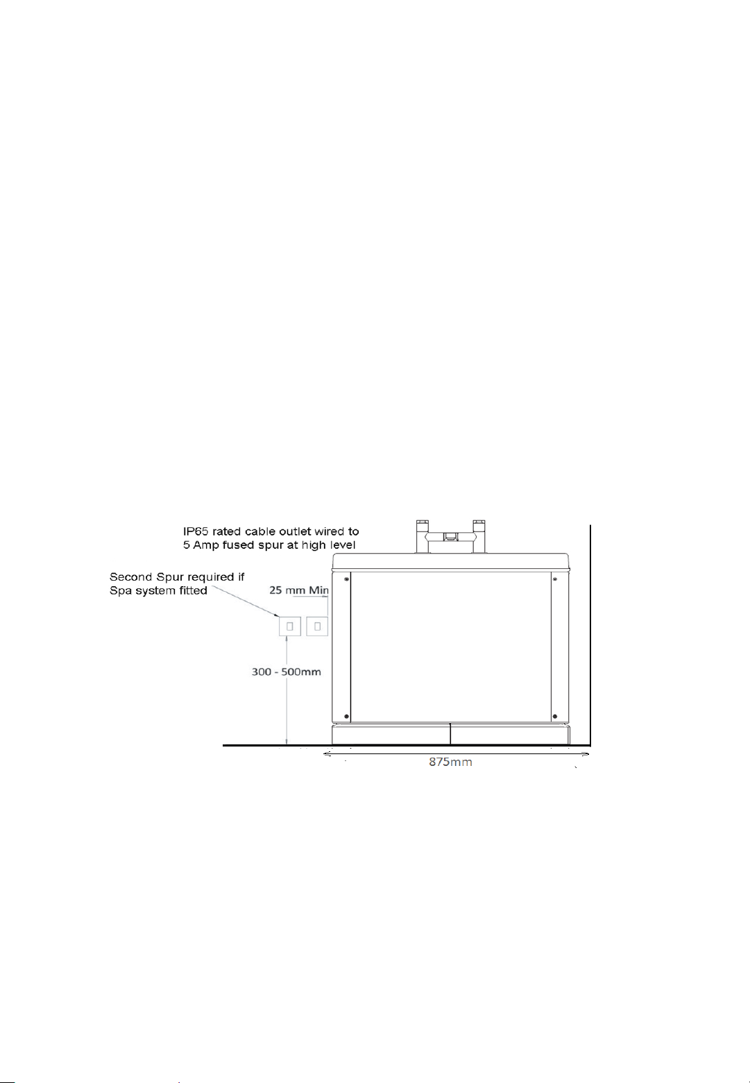
8) Make a permanent electrical connection following current IET regulations. Secure the cable
with conduit if required for cable protection. Ensure that the bath is fully earthed. Where a Spa is
fitted a 13 Amp IP65 rated switched fused spur is also required. Where applicable, junction boxes
should be fitted underneath the bath and affixed using a mechanical tool (screw or similar). Ensure
that a suitable location is chosen i.e. positioned off the floor, and behind bath panels.
A 30mA RCCD or RCBO is required in compliance in accordance with current Edition IET
regulations. This should be located outside the bathroom or on the consumer unit covering that
area of the building. Earth Bonding and Cross Bonding are to be fitted and tested for continuity in
accordance with IET regulations. The trailing flex should be protected by use of protective conduit.
Figure 6.0
The Spur box should be mounted between 300-500mm off the floor .
9) Fasten the chrome handset holder in place onto the side of the bath. Pre-drilled holes and
fixings are provided.
10) Plug in the handset. Offer up the handset connector to the front panel and fasten into place on
the front panel. Remove the plastic circlip from socket blanking plug next to the power supply on the
control box. Fit the handset Jack into the socket connector. Fit the circlip into place around Jack
ensuring that the two lugs locate correctly. There is a cable tie on the inside of the panel where
spare wire can be looped.

Talano & Alera Installation v2.6 9
Fitting Instructions
11) Offer up the side panel to the front of the bath. Guide it under the lip of the bath shell and then
mark the floor along the front of the panel to allow a wood batten (800mm x 25mm x 25mm) to be
fixed to the floor midway along the panel. This will prevent the panel moving at the base. Repeat as
required for other panels.
(End panel batten dimensions - 600mm x 25mm x 25mm)
Remove the panels and fix the wooded battens to floor –Take care to allow for the thickness of the
panel. Fix the batten 4mm in from the marked line to allow for panel thickness. Once fitted the side
panel can be clipped into position. Further work may be required before the end panels can be
fitted (see step 12).
Figure 7.0
Affix wooden battens to the floor to prevent the panel moving at the base.
12) End Panels may require trimming depending on the panel configuration:
One Side panel and one End –Trim end panel on the ‘wall side’
Two Side panels and one End panel - No trimming required
Two Side panels and two End panels - No trimming required
Where is trimming is required the trim should take place at the start of the ‘radius’ of the panel. We
recommend a wall batten is fitted in a similar manner to the floor battens.
13) Offer up panels into place and screw to battens and wall as needed.
14) Attach labels as required and fully test sequence prior to handover.

Talano & Alera Installation v2.6 10
Installation Addendum
Head End Base Plate
Figure 7.0
Please take note of the floor fixing locations illustrated on the base plate diagram. Precautions should
be taken to investigate floor integrity, paying particular attention to the locations marked above.

Talano & Alera Installation v2.6 11
Installation Addendum

Talano & Alera Installation v2.6 12
Installation Addendum

Talano & Alera Installation v2.6 13
Troubleshooting
Some basic checks are detailed below. If in doubt contact service support on +44 (0)1527 400022
Seat does not move
Check Spur Fused to ensure there is power to the unit.
Ensure the RCCB is working and has power to it. To test the RCCB push the test button; the RCCB
should interrupt power and the switch should trip. Push the RESET button; power should be
restored. If the RCCB fails to operate in this manner there is a problem with the electric supply and
the service department should be contacted.
If mains power is interrupted the bath will only work on battery backup to allow a user to exit the
bath and will then stop. Press ‘Seat out’ which will bring the seat down and out - do not use until the
fault is rectified. Once power is restored allow the batteries to recharge before operation (usually 3
hours).
If the bath fails to operate it is worthwhile checking that the handset cord and jack are still firmly
located into the panel connector.
Bath Judders/Noisy:
Usually occurs if the bath has not been fixed to the floor correctly or the bath is not level. Please
also ensure the chrome shaft is clean and free from dirt.
Bath Beeping
Mains power has failed to the unit- see section titled ‘Seat does not move’. The handset ‘battery’
symbol should be illuminated when the ‘Seat in’ button is pressed.
Bath Leaking:
Look for source of leak-typically caught flexi-hose on feed or waste. This can usually be remedied
by your own maintenance contractor.
Other manuals for TALANO
1
This manual suits for next models
5
Table of contents
Popular Bathroom Aid manuals by other brands

Hillsdale Furniture
Hillsdale Furniture 51028 quick start guide

COTTO
COTTO CT 0190 installation manual

Roth
Roth Mobeli 14002 68S instruction manual

Care & Independence
Care & Independence SWS 140 operating instructions

Eagle Health Supplies
Eagle Health Supplies 77 Series instruction sheet

Mobilex
Mobilex 302050 user manual

Graham Field
Graham Field Lumex 7103 manual

NRS
NRS M00778 User instructions

Joerns
Joerns Oxford Mermaid User instruction manual

keep living
keep living PRESSALIT CARE R4828 Mounting instruction

Helvex
Helvex Access ACC-105 installation guide

Galvin Engineering
Galvin Engineering CliniLever TC51FC1C Installation guidelines