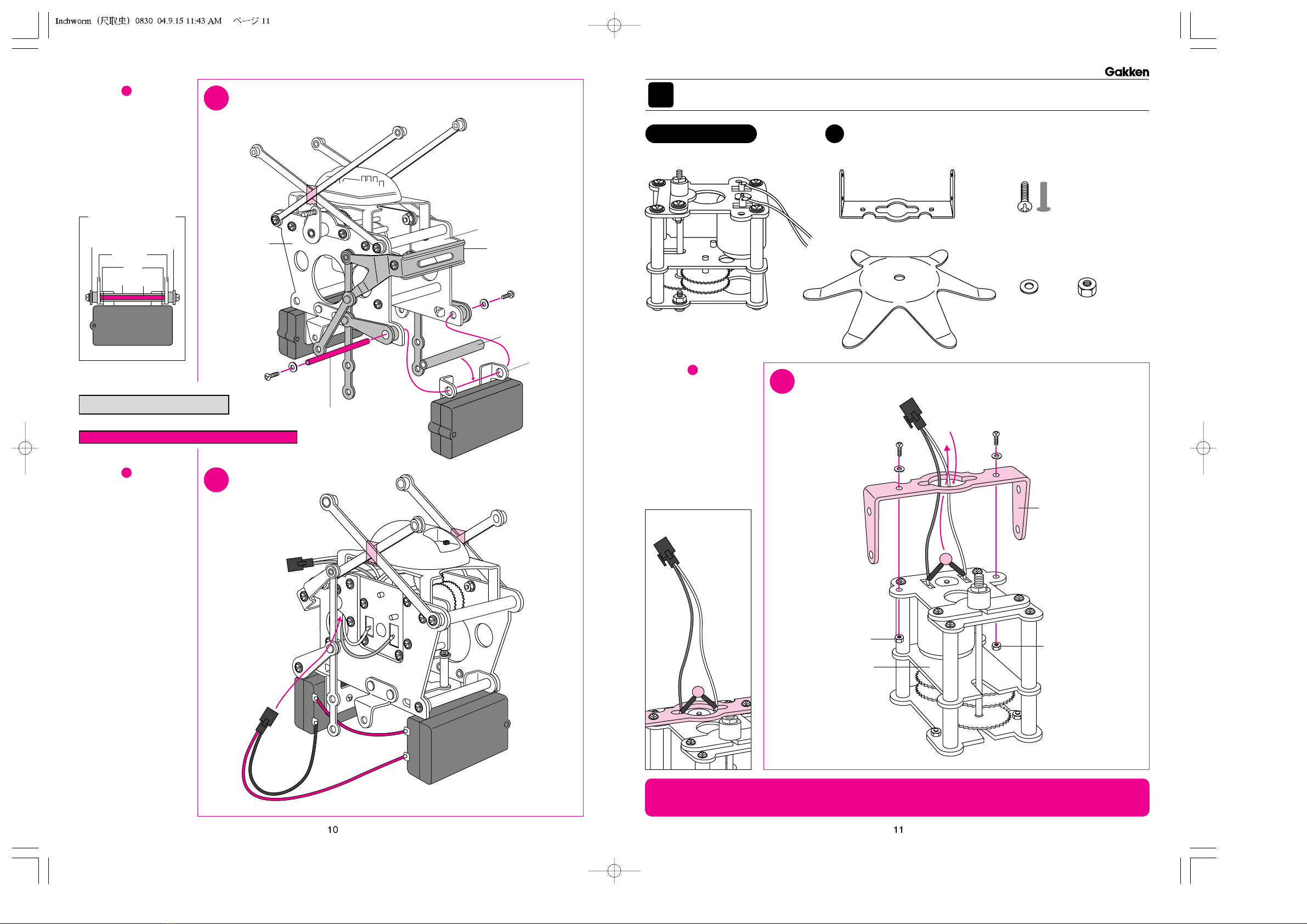
Gakken Mechamo Inchworm User manual

InstructionsforAssemblingandOperating
※Thepartslistisseparatelyattached.
OtonanoKagaku
TheSophisticatedScienceKitforAdults
MechamoInchworm

TheAnimal-shapedRobotDevisedfromMechanicalEngineering
メカモ
OtonanoKagaku
MechamoInchworm

Inchwormhastheforepartandthehinderpart,andthefrontsideandthebackside.Thefore
partiswiththeswitchofthelightsensorandwhenInchwormgoesforward,itgoestothis
direction.Thefrontsideisthatwithoutleadwiresofthemotorfordrive.Distinguishthefore
partandthehinderpart,andthefrontsideandthebacksideofthefiguresofthisbookletwhen
youassemble. switchofthelightsensor
A1body
A3motorfordrive
gearcrank
nut
nut
nut
nut
washer
Bringthecordsto
thearrowdirection.
washer
washer
washer
screw(8mm) screw(8mm)
screw(8mm)
screw(8mm)
1AttachingtheMotortotheBodyBeforeAssemblingtheKit
注意★メカモが動いているときは絶対にさわらないでください。たいへん危険
です。特に、小さいお子さんには、絶対にさわらせないようにしてください。
1.Understandingtherightdirection
2.
HowtoUseSuppliedTools
●wrench
Thewrenchcanbeusednot
onlyfortighteninganutbut
alsofortighteningscrews
frombothsidesasshownin
therightfigure.
screwdriver(cross-headedtip)
Thescrewdrivercanbe
usednotonlyfortightening
ascrewbutalsofor
tighteninganutasshownin
therightfigure.
Putthethinpartofthe
wrenchataslotof
thescrewtofix.
Turn.
Turn.
nut
※Pleasenotethatshapesofmaterialsmayappearslightlydifferentfrompicturesandillustrationsinthisbooklet.
Howtousethescrewdriver
(cross-headedtip)
thebackside
thefrontside
thehinderpart
Twelve8mm
screws Twelve
washers Ten
nuts
※Checkthelengthof
screwswiththisfigure.
※Therearesomemorenumbersofscrews,washers,
nutsandbushesincludedforsparethanareactuallyused.
Warning★DonottouchtheMechamowhileitisoperating.
Itisverydangerous.Particularly,neverletsmallchildrentouchit.
1
Figureー
SettheA3motorfor
driveontheA1body.
Fastenitatfour
pointswithscrews
andnutsasshownin
thefigure.
1AttachtheA3motorfordrivetotheA1body.
A3motorfordrive
A2body
A4gearshaftretainer
A5One48×6mm
threadedpipe
A6lightsensor A7sensorholder
A1body
theforepart
Howtousethewrenchwhen
tighteningscrewsfrom
bothsides
PARTS
A
Partstobeused
●ビスはしっかり締めてください。

theswitchofthe
lightsensor
※Payattentiontothedirection.
(Theswitchcomestotheforepart.)
Bringtheconnector
tothehinderpart.
A7lightsensor
A6sensorholder
nut
washer
screw
(8mm) screw(8mm)
washer
A1body
A2body
washer
screw(8mm)
washer
screw(8mm)
theforepart
thehinderpart
A1body
A2body A4gearshaftretainer
washer
screw(8mm)
screw(8mm)
washer A2body
A4gearshaftretainer
PuttheA2in
thisnarrow
space.
A3motorfordrive
gearcrank
screw(8mm)
washer
A5
threadedpipe
(48×6mm)
Putthewiresofthemotor
intothishole.
screw(8mm)
washer
screw
(8mm)
theswitchofthesensor
B2crankbar
B5
pipe(48×6mm)
A2body
B2crankbar
B4
threadedlongpipe
(64×4mm)
theforepart
thehinderpart
Notice:The2.5mmprojection
comesoutside.
Notice:The4.5mmprojection
comesinside.
theswitchofthelightsensor
screw(8mm)
washer
screw(8mm)
washer
theforepart
thehinderpart
A1body
B1crankbar
B5
pipe(48×6mm)
B1crankbar
B3
threadedlongpipe
(60×4mm)
A2body
A1
body
B1Twocrankbars
B6crankbar
B2Twocrankbars
B3Two60×4mmthreadedlongpipes
B4One64×4mmthreadedlongpipe
2.5mm
4.5mm
B5Two48×6mmpipes Six8mm
screws Six
washers
※Checkthelengthof
screwswiththisfigure.
1
1
1
2
2
2
A1body
thefrontside
thebackside
thefrontside
thebackside
thefrontside
thebackside
B1crankbars
nut
nut
nut
B6verticalcrank
washer
2
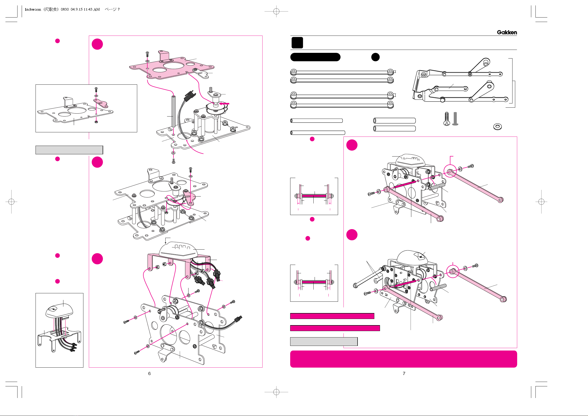
AttachingCrankBarsforMovingLegs
B
2
Figureー
Setthegearshaft
intothenotchofthe
A2bodyandconnect
theA1bodyandA2
bodywiththeA5
threadedpipe.
2CombinetheA1bodyandtheA2body.
3
Figureー
TurntheA4gear
shaftretainertothe
directionofthearrow
inthefigureand
fastentheendwitha
screwandanut.
Fastenbothendsof
theA4gearshaft
retainertotheA2
bodycompletely.
3
3
Attachthegear
shaftretainer.
4
Figureー
AttachtheA6
sensorholdertothe
bodyassembledat
Figureー with
screwsandnuts.
4Attachthe
sensor
holder.
Attachthegearshaftretainer
totheA2bodytemporarily.
A4
gearshaftretainer
A2body
screw(8mm)
washer
nut
A7lightsensor
A6
sensor
holder
Setthelightsensor
afterattachingthe
sensorholder.
5
Figureー
AttachB1crankbarsto
theA1bodyandtheA2
body.Makesurethatthe
2.5mmprojectionsofthe
crankbarscomeoutside.
5
5
AttachtwoB1crankbarstothehinderpartsoftheA1andtheA2bodies.
6
Figureー
AttachtheB2crankbars
tothebodyassembledat
Figureー .Makesure
thatthe4.5mm
projectionsofthecrank
barscomeinside.
6
ReversethefrontsideandthebacksideoftheA1andthe
A2bodiesandattachtwoB2crankbarstotheforepart.
※Checkthesizewiththis.
Full-scale
A5threadedpipe(48×6mm)(1)
B3threadedlongpipe(60×4mm)(2)
B5pipe(48×6mm)(2)
Theplacementofthebody
andthecrankbars
Theplacementofthebody
andthecrankbars
B4
B3
Theprojectionscomeinside.
B2B2 B5
B5
4.5mm4.5mm
Theprojectionscomeoutside.
B1 B1
A1 A2
A2 A12.5mm2.5mm
B4threadedlongpipe(64×4mm)(1)
注意★メカモが動いているときは絶対にさわらないでください。たいへん危険
です。特に、小さいお子さんには、絶対にさわらせないようにしてください。
Warning★DonottouchtheMechamowhileitisoperating.
Itisverydangerous.Particularly,neverletsmallchildrentouchit.
※T
herearesomemorenumbersofscrews,washers,nutsand
bushesincludedforsparethanareactuallyused.
PARTS
Partstobeused
※Checkthesizewiththis.
Full-scale

theforepart
thehinderpart
theswitchofthelightsensor
A1body
A2body
screw(8mm)
screw(8mm)
RaisetheB1crankbarsup.
washer
washer
B6
verticalcrank
B6
verticalcrank
B3
threadedlongpipe(60×4mm)
C5One52×4mmthreadedlongpipe
C6One70×4mmthreadedlongpipe
C4Two48×6mmpipes
C1batteryboxholder C2batteryboxholder C3Twobatteryboxes
Four8mmscrews
Four
self-tappingscrews
Four
washers
※Checkthelengthofscrewswiththisfigure.
theforepart
thehinderpart A2body
A1body
screw(8mm)
screw(8mm)
washer
washer
C2
batteryboxholder
C4
pipe(48×6mm)
C5
threadedlongpipe
(52×4mm)
C1
batteryboxholder
self-tappingscrew
self-tappingscrew
C2
batteryboxholder
C1
batteryboxholder
C3
batteryboxes
1
2
connector
connector
Becarefulbecausethesepartscomeoffeasily.
※
WhentheC5threaded
longpipedoesnユtfitinthe
holeintheC4pipe,loosen
theself-tappingscrew
fasteningthebatterybox
toadjusttheposition
ofthehole.
thefrontside
thebackside
B6
crankbar
1
2
self-tappingscrew
thefrontside
thebackside
C1・C2は、違う部品です。
C1・C2は、違う部品です。
正しくセットしてください。
3AttachingBatteryBoxes
C
8
Figureー
AttachtheC1andthe
C2batteryboxholders
totheC3batteryboxes.
8AttachtheC1andtheC2batteryboxholders
totheC3batteryboxesonebyone.
9
Figureー
AttachtheC2
batteryboxholder
withabatteryboxto
theforepartofthe
body.
9
Removethebatteries
whennotusingthe
machineforalongtime.
Also,oxyridedrycell
batteriesareunsuitable
becausetheyaretoo
powerful.
AttachtheC2batteryboxholdertotheforepart
ofthebody.
7
Figureー
AttachB6vertical
cranktothebody
assembledat
Figureー by
puttingthroughthe
B3threadedlong
pipeandfastening
bothendswith
screws.
7
6
AttachB6verticalcranktothehinderpartofthebody.
Theplacementofthebody
andtheverticalcrankbar
B6
A2 A1
B3
C4pipe(48×6mm)
C5threadedlongpipe(52×4mm)(1)
Theplacementofthe
forepartofthebody
andtheC2battery
boxholder
A1・2
C2
C5 C4
C3batterybox
Donot
mistakethe
positiveand
negativeterminals.
screw
Loosenthescrewwitha
screwdriverandopenthelid.
Setbatteriesintheright
wayandscrewthelid.
Howtoputbatteries
TapingB1andB2crank
barstemporarilymakes
theworkeasier.
Removethetapeat .
22
TapingB1andB2crank
barstemporarilymakes
theworkeasier.
Removethetapeat .
22
注意★メカモが動いているときは絶対にさわらないでください。たいへん危険
です。特に、小さいお子さんには、絶対にさわらせないようにしてください。
Warning★DonottouchtheMechamowhileitisoperating.
Itisverydangerous.Particularly,neverletsmallchildrentouchit.
※Therearesomemorenumbersofscrews,washers,
nutsandbushesincludedforsparethanareactuallyused.
PARTS
Partstobeused
※Checkthesizewiththis.
Full-scale
なおクランクバーの重なりを
間違えないようにしてください。
なおクランクバーの重なりを
間違えないようにしてください。

この穴にコネクターと
コンデンサーを通しておく
1
2
theforepart
thehinderpart
screw(8mm)
washer
washer
screw(8mm)
C4
pipe(48×6mm)
C6
threadedlongpipe
(70×4mm)
Puttheconnector
throughthishole.
theforepart
thehinderpart
Six8mmscrews
Seven
washers Seven
nuts
※Checkthesizewiththisfigure.
D1motorforturn D2verticalcrankholder
D3legsforturn
この穴にコネクターと
コンデンサーを通しておく
screw(8mm)
screw(8mm) washer
washer
nut
nut
D1motorforturn
D2verticalcrankholder
A2body
A1body
2
1
thebackside
thefrontside
※Leadwires
arenot
illustrated.
thefrontside
thebackside
※WhentheC6threadedlong
pipedoesnユtfitinthehole
intheC4pipe,loosenthe
self-tappingscrewfastening
thebatteryboxtoadjust
thepositionofthehole.
4AssemblingtheMotorforTurn
D
10
Figureー
AttachtheC1
batteryboxholder
withabatteryboxto
thehinderpartofthe
bodyandfastenthe
B6verticalcrankat
thesametime.
10
AttachtheC1batteryboxholdertothehinder
partofthebody.
11
Figureー
Afterattachingthe
C1andtheC2
batteryboxes,wire
asshowninthe
figure.
11
Wiring.
12
Figureー
AttachtheD2
verticalcrankholder
totheD1motorfor
turn.Atthispoint,
donユtforgettoput
thewiringconnector
ofthemotorthrough
theholeintheD2
verticalcrankholder.
12
AttachtheverticalcrankholdertotheD1motor
forturn.
C4pipe(48×6mm)
C6threadedlongpipe(70×4mm)(1)
Theplacementofthehinder
partofthebodyandthe
C1batteryboxholder
A1&2
C6
B6 B6
C4
C3batterybox
注意★メカモが動いているときは絶対にさわらないでください。たいへん危険
です。特に、小さいお子さんには、絶対にさわらせないようにしてください。
Warning★DonottouchtheMechamowhileitisoperating.
Itisverydangerous.Particularly,neverletsmallchildrentouchit.
※Checkthesizewiththis.
Full-scale
※Therearesomemorenumbersofscrews,washers,
nutsandbushesincludedforsparethanareactuallyused.
PARTS
Partstobeused
B6
verticalcrank
C1
batterybox
holder
C1

Two2mm
bushes Two7.5mm
bushes
EightwashersFivenuts
nut
washer
D3legsforturn
D1motorforturn
D2verticalcrankholder
Setthelegssothat
theshapeofthe
holefitson.
screw(8mm)
screw(8mm)
washer
washer
washer
washer
screw(8mm)
screw(8mm)
B6verticalcrank
nut
nut
nut
nut
Four8mm
screws
Two15mm
screws
※Checkthelengthofscrewswiththesefigures.
E1V-crank
(*Itisattachedtothefrontside.)
E1crankbar
E2V-crank(*Itisattachedtothefrontside.)
E3TwoV-crankconnectors
B6verticalcrank
Puttheconnectorof
themotorforturn
throughthishole.
theforepart
thehinderpart
theforepart
thehinderpart
connectorofthe
lightsensor
wiresfromthemotorforturn
(greenandwhite)
wiresfromthemotorfordrive
(yellowandblue)
Whenitisdifficulttoset
thebodyonthemotor
forturn,trythe
followingtwothingsfor
easyassembling.
1.PuttheB6vertical
crankupandthemotor
forturndown.
2.Removethelegsfor
turntemporarily.
2
1
2
1
thefrontside
thebackside
thebackside
thefrontside
wiresfromthebatteries
(redandblack)
5AttachingV-cranks
E
13
Figureー
SettheD3legsfor
turnontheD1motor
forturnandfasten
firmlywithanut.
13
AttachtheD3legsforturn.
14
Figureー
Setthebody
assembledat
Figureー onthe
motorforturn
assembledat
Figureー .
(Attachthemotor
forturntothebody
attheB6vertical
crank.)
14
13
11
Setthemotorforturntothebody.
15
Figureー
Settheleadwires
fromthemotorfor
drive,themotorfor
turn,andthebattery
boxesintothelead
wireconnectorsof
thelightsensorso
thatthesamecolor
wiresareconnected.
Besuretosetthe
wiresatthispoint
becauseitbecomes
difficulttowire
afterward.
15
Wiring.
注意★メカモが動いているときは絶対にさわらないでください。たいへん危険
です。特に、小さいお子さんには、絶対にさわらせないようにしてください。
Warning★DonottouchtheMechamowhileitisoperating.
Itisverydangerous.Particularly,neverletsmallchildrentouchit.
※Therearesomemorenumbersofscrews,washers,
nutsandbushesincludedforsparethanareactuallyused.
PARTS
Partstobeused

A2
body
A1
body
E1
V-crank
(*Itisattached
tothefrontside.)
E2
V-crank
(*Itisattached
tothebackside.)
bush(7.5mm)
washer
thescrew(15mm)
B6
verticalcrank
theforepart
the
hinder
part
gearcrank
switchofthelightsensor
TheE1crankbar
forconnectionto
thegearcrankis
attachedhere.
E1
bush(7.5mm)
screw(15mm)
A2
E2
bush(7.5mm)
screw(15mm)
A1 theforepart
thehinderpart
bush(7.5mm)
washer
thescrew(15mm)
E3V-crankconnector
E3
V-crank
connector
E1
V-crank
E2
V-crank
screw(8mm)
screw
(8mm)
screw(8mm)
washer
washer
nut
nut
screw
(8mm)
nut
washer
washer
nut
theforepart
Don'tforgettoputintwobushes.
※WhensettingtheB6andtheE1crankbarsontheshaft
ofthegearcrank,pushuptheendsofcrankbarsalittle.
Don'tforgettoputinabush.
thehinder
part
E2
V-crank
E1
V-crank
nut
washer
bush(2mm)
washer
gearcrank
bush
(2mm)
SideView
gearcrank
2
1
E1crankbar
E1crankbar
B6crankbar
thebackside
thefrontside
thefrontside
thebackside
thefrontside
theback
side
B6
verticalcrank
thebackside
thefrontside
washer
washer
Theplacementofthe
E1V-crankandthebody
Theplacementofthe
E2V-crankandthebody
Howtofastenthecrank
barstothegearcrank
18
Figureー
FastentheB6crank
barandtheE1crank
bartothegear
crank.
●Notice
Attachthepartsin
thefollowingorder.
bush(2mm)
B6crankbar
washer
bush(2mm)
E1crankbar
washer
nut
※Putthebushesin
theholesinthebar
orthecrankfirst,
thenscrewthenut
on.(Twobushesare
needed.)
18
FastentheB6crankbarandtheE1crankbar
tothegearcrank.
19
Figureー
FastentheE1and
theE2V-crankswith
twoE3V-crank
connectors.
19
FastenthetwoV-crankswithE3V-crankconnectors.
16
Figureー
FastentheE1
V-cranktotheA2
body.Becarefulnot
tomistaketheE2
V-crankfortheE1
V-crank.
Don'tforgettoputin
abush.
16
FastentheE1V-cranktotheA2body.
17
Figureー
FastentheE2
V-cranktotheA1
body.
Don'tforgettoputin
abush.
17
FastentheE2V-cranktotheA1body.
nut
washer
bush
(2mm)
E1
B6
washers
nut
bushes(2mm)
E1 B6
注意★メカモが動いているときは絶対にさわらないでください。たいへん危険
です。特に、小さいお子さんには、絶対にさわらせないようにしてください。
Warning★DonottouchtheMechamowhileitisoperating.
Itisverydangerous.Particularly,neverletsmallchildrentouchit.

screw(8mm)
nuts
washer
F1legs
F1legs
F2legconnector
F2legconnector
screw(8mm)
screw(8mm)
screw
(8mm)
washer
washer
washer
nuts
F3Two52×4mmthreadedlongpipes
Sixteen8mm
screws Sixteen
washers Eight
nuts
※Checkthelengthofscrewswiththisfigure.
F1Fourlegs
F2Twolegconnectors
F4One64×4mmthreadedlongpipe
F5One60×4mmthreadedlongpipe
F6Two48×6mmpipes
F3
threadedlongpipe
(52×4mm)
F3
threadedlongpipe
(52×4mm)
E1
V-crank
E1
V-crank
E3
V-crank
connector
screw(8mm)
screw(8mm)
washer
washer
F1leg
B1crankbars
screw
(8mm)
screw(8mm)
screw(8mm)
washer
washer
washer
F4
threadedlongpipe
(64×4mm)
F5
threadedlongpipe
(60×4mm)
F6
pipe(48×6mm)
washer
screw(8mm)
F1leg
F6
pipe(48×6mm)
F4・F5
F6
F1
2
1
thehinder
part
theforepart
thefrontside
theback
side
Removethetapestyingtemporarilythecrankbarstogether.
thehinderpart
theforepart
thefrontside
thebackside
B
1
*
B
1
*
Connectthelegpartsandthecrankbars
assembledatFigureー and.
6AttachingLegstotheBody
F
Theplacementofthe
V-cranksandthelegs
Theplacementofthe
crankbarsandthelegs
21
Figureー
Attachlegparts
assembledat
Figureー tothe
foreandthehinder
tipsoftheV-cranks.
Setbothlegparts.
21
20
Attachlegpartstotheforeandthehinderparts
oftheV-cranks.
22
5 6
20
Figureー
Assembletwoleg
partsusingF2leg
connectors.
20
Maketwolegparts.
F3threadedlongpipe(52×4mm)(2)
F4threadedlongpipe(64×4mm)(1)
F6pipe(48×6mm)(2)
F3
F1
F5threadedlongpipe(60×4mm)(1)
Figureー
Connectthecrank
barsattachedat
Figureー and to
thetopofbothfore
andhinderlegparts.
22
6
5
*Theprojectionsfaceoutside
incaseoftheB2crankbars.
注意★メカモが動いているときは絶対にさわらないでください。たいへん危険
です。特に、小さいお子さんには、絶対にさわらせないようにしてください。
Warning★DonottouchtheMechamowhileitisoperating.
Itisverydangerous.Particularly,neverletsmallchildrentouchit.
※Therearesomemorenumbersofscrews,washers,
nutsandbushesincludedforsparethanareactuallyused.
PARTS
Partstobeused
※Checkthesizewiththis.
Full-scale
※Checkthesizewiththis.
Full-scale

23
Figureー
You'vefinishedthe
assembly.
23
※Removethe
batterieswhennot
using.Also,oxyride
drycellbatteriesare
unsuitablebecause
theyaretoo
powerful.
NowtheMechamo
inchwormiscomplete!
↓Viewfromthe
BackSide
↓ObliqueTopViewof
theFrontSide
←ViewfromtheForePart
24
Howtooperate.(Howtousetheremotecontrol)
Figureー
First,turnonthe
switchofthelight
sensor.Then,you
canoperatethe
machinewiththe
remotecontrol.The
machinegoes
forwardandbackor
turnsrightandleft
accordingtothe
operationofthe
controlstick.See
therightillustrations
fortheoperation.
24
turntothe
leftforward
turntothe
rightback turntothe
leftback
turntothe
rightforward
rotate
counterclockwise
onthespot
rotate
clockwise
onthespot
goforward
goback
control
stick
※Itrotateswhen
bothforeand
hindlegsare
intheair.
※Itrotateswhen
bothforeand
hindlegsare
intheair.
Howtoputbatteries
intheremotecontrol
Donotmistakethe
positiveandnegative
terminals.
Loosenthescrewwitha
screwdriverandopenthelid.
Setbatteriesintheright
wayandscrewthelid.
off on
OFF
ON
Other Gakken Toy manuals
Popular Toy manuals by other brands

Fit N'Fun
Fit N'Fun 9300M Hickory Hills Owner's manual and assembly instructions

Quick
Quick Outdo 600 Pro Assembly and maintenance manual

Neopets
Neopets Voice Activated Kougra Instruction guide

HPI Racing
HPI Racing TROPHY FLUX TRUGGY instruction manual

LEGO
LEGO 31313 EV3RSTORM quick guide

marklin
marklin 110097 manual

Home Accents Holiday
Home Accents Holiday TY416-2011 Assembly instructions

Eduard
Eduard Su-57 quick start guide

Flyitalia
Flyitalia MD 3 RIDER Aircraft Maintenance Manual

REVELL
REVELL KIT 5244 Assembly manual

SAB Heli Division
SAB Heli Division Goblin URUKAY CARBON manual

Ripmax
Ripmax BOOMERANG TORUS manual