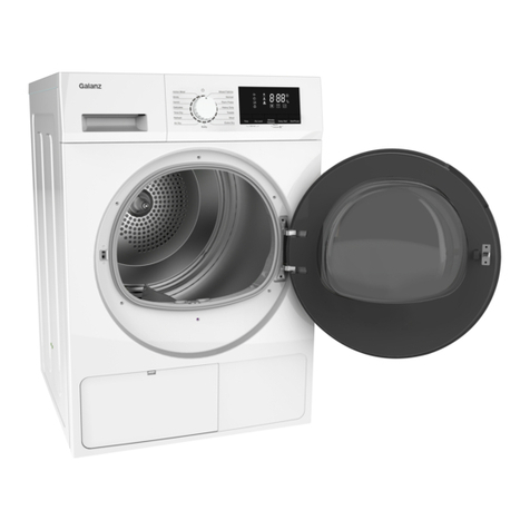
Galanz DC-80S1E User manual

1
Galanz
Service Manual
Condensing Dryer
model:DC-80S1E,DC-80S1U
contents pages
1. Technical data 2
2. Parts list 2
3. Picture of complete machine 6
4. Explosive view 7
5. wiring scheme 13
6. circuit diagram 14
7. key function 15
8. indicator light function 16
9. program function 18
10. fault detected f unc tion 19
11. Malfunction code 22
12. breakdown maintenance 22
single phase asynchronous motor

2
1. Technical Data
1.1 data table
Overall size
595*630*845mm
Drum Capability
8KG
Weight
45KG
Power Connection
Voltage:230V Frequency:50Hz
Maximum Power
DC-80S1E(2500W)DC-80S1U(2700W)
1.2 Electrical Component
1.21 Heating Tube
1.22 Rated Voltage:230V
1.23 rated power:800W/1400W ,deviation range: +5% -10%
1.24 temperature controller:TOD 36FXE L170C
1.25 temperature sensor:B25/75=3965K ±1%
1.3 Main Motor
1.31 Type:Single phase asynchronous motor
1.32 Rated Voltage:230V
1.33 Frequency:50Hz
1.34 Power Consumption:140We
1.35 Class of insulation: F
1.36 Condensation pump
1.37 voltage:220-240V
6.8 Frequency:50Hz
6.9 Resistance:750+/-750hm
6.10 Rate:3000/min
6.11 Class insulation: F
7. Micro switch
7.1. Technical parameter:16(3)A 250V T125
8. Capacitance
8.1 Technical parameter
:DC-80S1E(10μF±5% 450V) DC-80S1U(9μF±5% 450V)

3
2. Parts list
Model:
S/N
Model
Mane
Quantity
Material quality
1
DC80S1E.5.1
Door AS
1
Binder
2
DC80S1E.6
Down Panel AS
1
Binder
3
DC80S1E.5.2
Front Cover AS
1
Binder
4
DC80S1E.3
Control Panel AS
1
Binder
5
DC80S1E.1.2
Door supporter AS
1
Binder
6
DC80S1E.1.3
Side Board AS
2
Binder
7
DC80S1E.4
Water Bracket AS
1
Binder
8
DC80S1E.1.1
Base AS
1
Binder
9
DC80S1E.7
Drum AS
1
Binder
10
DC80S1E.2
Top Cover AS
1
Binder
11
DC80S1E.9
Drum Support AS
1
Binder
12
DC80S1E.1.4
Back Cover AS
1
Binder
13
DV60Q1E.3.1-1
Select Knob
1
ABS
14
DV60Q1E.3.1-2
Knob Bracket
1
ABS
15
DV60Q1E.3.1-3
Knob Shaft
1
POM
16
DC80S1E.3-1
Control Panel
1
ABS
17
DC80S1E.3-4
Select Button
1
ABS
18
DC80S1E.3-3
Start Button
1
ABS
19
DC80S1E.3-8
1 Lamp Board 1
1
PC-L-125Y
20
DC80S1E.3-9
2 Lamp Board 2
1
PC-L-125Y
21
DC80S1E.3-6
LED Display
1
PC-L-125Y
22
DC80S1E.3-7
LED Bracket
1
ABS
23
DC80S1E.8-3
Operate PCB
1
Binder
24
DC80S1E.3-2
PCB Case
1
ABS
25
DC80S1E.8-2
Main PCB
1
Binder
26
DC80S1E.5.1-1
Door Outer Frame
1
ABS
27
DV60Q1E.5-6
Door Hinge Cap
4
POM
28
DC80S1E.5.1-6
Door Hook Fixture
1
PP116
29
DC80S1E.5.1-7
Door Hinge Fixture
1
PP116
30
DC80S1E.5.1-3
Door Hook
1
Zn-Al
31
DC80S1E.5.1-9
Micro Switch Pole
1
POM
32
DC80S1E.5.1-4
Door Hinge
2
Zn-Al
33
DC80S1E.5.1-2
Door Inner Frame
1
PP116
34
DC80S1E.5.1-8
Door Gasket
1
EPDM
35
DC80S1E.5.1.1
Door Filter Bracket
1
Binder
36
DC80S1E.5.1-5
Door Inner Frame
1
PP116
37
DC80S1E.4-2
Pull Cover
1
ABS
38
DC80S1E.4-1
Water Tank
1
PP
39
DC80S1E.1.1-10
Water Pump Pipe
1
PP+ rubber

4
40
DC80S1E.4-4
Water Pipe Linker
1
PP
41
DC80S1E.4-5
Water Bracket
1
PP116
42
DC80S1E.1.1-11
Overflow water Pipe
1
PP+ rubber
43
DC80S1E.6-4
Grid Axes
1
2Cr13
44
DC80S1E.6-1
Down Panel
1
ABS
45
DC80S1E.6-2
Grid
1
ABS
46
DC80S1E.6-3
Lock Button
1
Binder
47
DV60Q1E.7.1-1
Lifter
2
PP116
48
DC80S1E.7.1
Drum Rivet joint module
1
Binder
49
DC80S1E.5.2-2
Door Lock Decorative
Cover
1
PP116
50
DC80S1E.5.2-3
Door Hinge Decorative
Cover
2
PP116
51
DC80S1E.5.2-1
Front Cover
1
CRP
52
DC80S1E.5.2-4
Door Lock AS
1
Binder
53
DC80S1E.1.2-13
Micro Switch Rocker
1
PA66+30%GF
54
DC80S1E.1.2-14
Micro Switch spring
1
65Mn
55
DC80S1E.1.2-12
Micro Switch Fixture
1
POM-23P
56
XDQ09-03
Micro Switch
1
Binder
57
DV60Q1E.8-1
Lamp Socket
1
Binder
58
DV60Q1E.8-4
Lamp
1
Binder
59
DC80S1E.5.1.1
Filter Net Bracket
1
Binder
60
DC80S1E.1.2-8
Door Supporter Gasket
1
EPDM
61
DC80S1E.1.2-4
Felt
1
sponge+felt
62
DC80S1E.1.2-2
Door Supporter Cover
1
PP116
63
DC80S1E.1.2-5
Lamp Cap
1
PC-L-125OY
64
XDQ07-03
Thermistor
1
Binder
65
DC80S1E.1.2-16
Temperature Sensor
Gasket
1
EPDM
66
DC80S1E.1.2-3
Door Supporter Vent
Cover
1
PP116
67
DC80S1E.1.2-1
Door Supporter
1
PP116
68
GB/T41-2000
Nut
4
galvanized
69
XLD01-10
Washer
6
galvanized
70
DC80S1E.1.2-19
Front Wheel Axes
2
Steel 45#
71
DC80S1E.1.2.3
Wheel AS
4
Binder
72
GB/T6177.1-2000
M8 Hex Flange Nuts
4
galvanized
73
DC80S1E.1.2-20
Lamp Gasket
1
EPDM
74
DC80S1E.1.2-10
Moisture Sensor
2
SS430
75
DC80S1E.1.2-18
Wheel Axes
2
Steel45#
76
DC80S1E.7.1
Drum Fixture AS
1
Binder
77
DC80S1E.8-1
Heater AS
1
Binder
78
DC80S1E.1.1-14
Leg
4
PP116

5
79
DC80S1E.1.1-1
Base Bracket
1
PP116
80
XDQ11-05
Capacitor
1
Binder
81
XDQ20-01
Pump
1
Binder
82
DC80S1E.1.1-8
Float
1
EPS
83
DC80S1E.1.1-15
Baffle
1
PP116
84
DC80S1E.1.1-7
Pump Fixture Cover
1
PP116
85
DC80S1E.1.1.1-4
Idler Spring
1
65Mn
86
DC80S1E.1.1.1-5
Circulate Fan
1
HS-PA66NM-30G
87
XLD01-08
Fan Washer
2
galvanized
88
DC80S1E.1.1.1-3
Motor Cushion
2
NBR
89
DC80S1E.1.1.1-2
Motor Cover
2
POM
90
XDQ04-15
Motor
1
Binder
91
DC80S1E.1.1.1-8
Idler Washer
1
POM
92
DC80S1E.1.1.1.1.
Idler AS
1
Binder
93
DC80S1E..1.1.1-9
Front Fan Cover
1
PP116
94
DC80S1E..1.1.1-6
Condensation Fan
1
HS-PA66NM-30G
95
DC80S1E..1.1-5
Back Fan Cover
1
PP116
96
DC80S1E..1.1.1-1
Motor Fixture
2
Hot-dip galvanized
sheet
97
DC80S1E..1.1-4
Circulate Fan Cover
1
PP116
98
XDQ09-04
Micro Switch
2
Binder
99
DC80S1E..1.1.2
Condensation AS
1
Binder
100
DC80S1E..1.1-3
Condensation Vent
1
PP116
101
DC80S1E.1.1-2.
Circulate Vent
1
PP116
102
DC80S1E..1.1-13
Micro Switch Cover
1
PP116
103
DC80S1E..1.1-12
Micro-V Belt
1
Poly belt 7PH1950
104
XDQ05-48\L=1.5M
VDE Power Cord
1

6
3. Picture of Complete Machine

7
4. Explosive view

8

9

10
5. Electric Diagram

11
6. Circuit Diagram

12
7. Key Function
“ ” Start/Pause button
Press this button to start or pause the machine. After choosing the Buzzer function,
it will make out a “B”sound every time you press the button.
“Delay Start”button
By pressing this button, you can select delay programme from 1~ 24 hours. This
option must be selected after having selected the programme. After selecting the
Buzzer function, it will make out a “B”sound every time you press the button.
“Delicate”button
Different delicate programmes increase or decrease time. It will make a “B”sound
every time you press the buttons after choosing the Buzzer fuction.
“Quick”button
The drying time will decrease about 10 minutes after pressing this button, but this
cannot combine with the function of Delicate.
“Buzzer”button
。Press this button to turn on or off the Buzzer.

13
“ ” Child Lock combination key
同时按下“Delay Start”和“Delicate”
Press meantime “Delay Start” and “Delicate”button for several seconds to turn on or off the
Child Lock Fuction.
8. Indicator Light Function
“Buzzer”light
。This light indicates the Buzzer function is on. Pressing buttons after selecting
required programmes or rotating the dial when the appliance is running, the
appliance will make out buzzing sound. Buzzer light out indicates the Buzzer is off,
so during the process it won’t make our buzzing sound.
“Delicate”Light
Delicate light is long on indicates the “Delicate”programme is selected. Delicate light
out indicates this programme is not selected.
“Delay Start”Light
“Delay Start”light is long on indicates “Delay Start”programme is selected.
“Delay Start”light is out indicates “Delay Start”function is not selected.
“Child Lock”Light
“Child Lock”light indicates this function is on, or its off.
“Drying”Light
This light indicated the appliance is in the drying phase.
“Cooling”Light
This light indicates that the appliance is in the cooling phase.
“End”Light
This light is on after all the phases are finished.
“Start/Pause”
。When the programme is running, the “Start/Pause”light will be on. When the light
is flashing, it indicates the programme is paused.
“Condensor”Light
It comes when all the selected programmes are finished, which remind you to
clean the condenser.
The light flashes when system experiences failure, during which the digital screen
will display a corresponding fault code.

14
“Tank”Light
It comes when the water container is full, which remind you to empty the
water container.
“Filter”Light
It comes one after each load to remind you to clean the filter.
“Quick”Light
The light is on after selected this programme, or its not selected.
20. Program Function
Buttons
Buzz
er
Quick
Delicate
Delay Start
Start/Pause
(Programe)
COTTON
Heavy
2:50
2:40
3:40
○
○
Strong
2:40
2:40
3:30
○
○
Normal
2:30
2:40
3:20
○
○
Damp
2:20
ErS
3:10
○
○
Iron
2:10
ErS
3:10
○
○
SYNTHETICS
Syn-Extra
1:40
ErS
2:10
○
○
Syn-Cupbo
ard
1:30
ErS
2:00
○
○
Syn-Iron
1:00
ErS
1:30
○
○
TIME
90 分min
1:30
ErS
ErS
○
○
60 分min
1:00
ErS
ErS
○
○
30 分min
0:30
ErS
ErS
○
○
SPECIAL
Anti-Bacteri
al
2:15
ErS
ErS
ErS
○
Silk
1:50
ErS
ErS
ErS
○
Freshen-up
1:00
ErS
ErS
ErS
○
Air-Dry
0:25
ErS
ErS
ErS
○
Table 1, “Ers”unavailable “○”available

15
9. Fault Diagnosis Function
(E1)Temperature Sensor Malfunction diagnosis (E1)
(1)Condition: Temperature Sensor Malfunction or not connecting
(2)System Reaction:
All the selected programmes stop. Indicator lights go out. The digital tube displays
fault code”E1”. All of the buttons and stall switch have no reaction. Whether the
Buzzer is on or not, it will raise the Error alarm for 5 seconds every 5 minutes.
(E3)Heating wire temperature sensor is open-circuit or short-circuit.
(1)Condition: heating wire temperature sensor malfunction.
(2): system reaction:
All the selected programmes stop. Indicator lights go out. The digital tube displays
fault code”E3”. All of the buttons and stall switch have no reaction. Whether the
Buzzer is on or not, it will raise the Error alarm for 5 seconds every 5 minutes.
(E2)Heating wire assembly malfunction diagnosis
(1)condition
Temperature never gets to 32℃even though the system works with no stop to the
end of the cooling process under the “Heavy”、“ Strong”、“ Normal”these
three switches. Do not detect the malfunction when the appliance suspended and
door open during the operation.
(2)system reaction
All the selected programmes stop. Indicator lights go out. The digital tube displays
fault code”E3”. All of the buttons and stall switch have no reaction. Whether the
Buzzer is on or not, it will raise the Error alarm for 5 seconds every 5 minutes.
door lock diagnosis(dop)
(1)Condition
The door is opened when the system starts or during the operation. When the door
is opened at the end of the cooling process, the operation is finished.
(2)system reaction
All the selected programmes stop. Indicator light is the same to suspend. The
digital tube display fault code “dop”. Except the “Start/Pause”and “Buzzer”
buttons, the rest have no reaction, same to the stall switch. When the door is closed,
the system gets to a normal suspension state.

16
Selection procedure error diagnosis
(1)Condition
①Under the state of programme selected, the system selects programme
which is not selected.
②Stall switch changes switch during normal operation.
(2)system reaction
The digital tube displays fault code “Ers”, then it displays the setting time or the
time rest. If the digital tube flashes the fault code while the Buzzer function is on,
then the system will Buzz the alarm.
(E6)Condenser malfunction diagnosis
(1)Condition: Condenser is removed
(2)System reaction
All the selected programmes stop. “Condenser”indicator light flashes. Digital tube
displays fault code “E6”. All of the buttons and stall switch have no reaction.
Whether the Buzzer is on or not, it will raise the Error alarm for 5 seconds every 5
minutes.
Water tank diagnosis
(1)Condition: The water in tank is full
(2)system reaction
All the programmes stop. System gets into the state of suspension, and the “Tank”
flashes in the digital indicator light.
10 Malfunction Code
fault
code
E1
E2
E3
dOP
ErS
E6
fault
temperature
sensor
open-circuit
or
short-circuit
Heating
wire not
working
heating wire
temperature
sensor
open-circuit
or
short-circuit
door is
opening
selection
procedure
error
Condenser
is removed

17
11 Breakdown Maintenance
NO.
Malfunction
fault
indicator
light
Possible Cause
Solution
1
Temperature
Sensor CTN
E1
1、whether the sensor is
malfunctioning?
2、Is the plug plugged in
firmly?
3、Is it short-circuit?
1、replace the sensor
2、re-plug in
3、replace the wire
2
heating wire
temperature
sensor
open-circuit
or
short-circuit
E3
1、Is the heating wire
temperature sensor
malfunctioning?
2、Whether the plug is
plugged in firmly?
3、Is it short-circuit?
1、re-plug in
2、replace the wire
3、replace the heating wire
3
heating wire
assembly
E2
4、1、Is the plug plugged in
firmly?
2、Whether the heating wire
is malfunctioned?
1、re-plug in the plug
2、replace the heating wire
4
door open
dop
5、1、Is the plug plugged in
firmly?
2、Whether the Micro-switch
is malfunctioned?
1、replace the Micro-switch
2、re-plug in the plug
6
condenser
E6
1、Is the condenser
installed not good
enough?
2、Is the Micro-switch
malfunctioned?
3、Is the plug contact poor?
1、Re-install condenser in
the right way.
2、replace the
Micro-switch
、
This manual suits for next models
1
Table of contents
Other Galanz Dryer manuals
Popular Dryer manuals by other brands

Bosch
Bosch WTE84101AU Operating and installation instructions

Miele
Miele T 4859 Ci SUPERTRONIC operating instructions

Grundig
Grundig GT55823F6 user manual

Frigidaire
Frigidaire 131679000B Use & care guide

Alliance Laundry Systems
Alliance Laundry Systems D310IE3B Use and care guide

AEG
AEG TR718L4B user manual