Galcon DCS Series User manual

GALCON DC1S 6051 / DC4S 6051
1
DCS – Professional Advanced Computerized
Irrigation Controllers
Operating and Installation Instructions
Main Features:
* Independent Valve Programming
* Weekly or Cyclical Programming
* Up to 4 Operations Daily In
Weekly Program Mode
* Irrigation Window in Cyclical
Program Mode
* Irrigation period: From 5 seconds
to 12 hours
* Irrigation Cycles in Cyclical
program mode: From Once a
minute to Once a Month
* Withstands Harsh Climatic
Conditions
* WP only – Water-resistant
* Simple, Four-Button Programming
* Single Valve (DC1s) to 4 Valve (DC4s) Capacity
* Optional Manual Operation
* Operates On Two 9V Alkaline Batteries
* Valve type compatibility:
Galcon 2-way (blue panel), Galcon 3-way or other 3-way hydraulic
valves with a command valve (orange panel)
* Program lockout sensor option; individual valve association to sensor
Note: This user manual covers models operating both 2-way and 3-way
valves.

Table of Contents
2
1. Parts Identification.............................................................................3
2. Setting Up the Irrigation Controller..................................................3
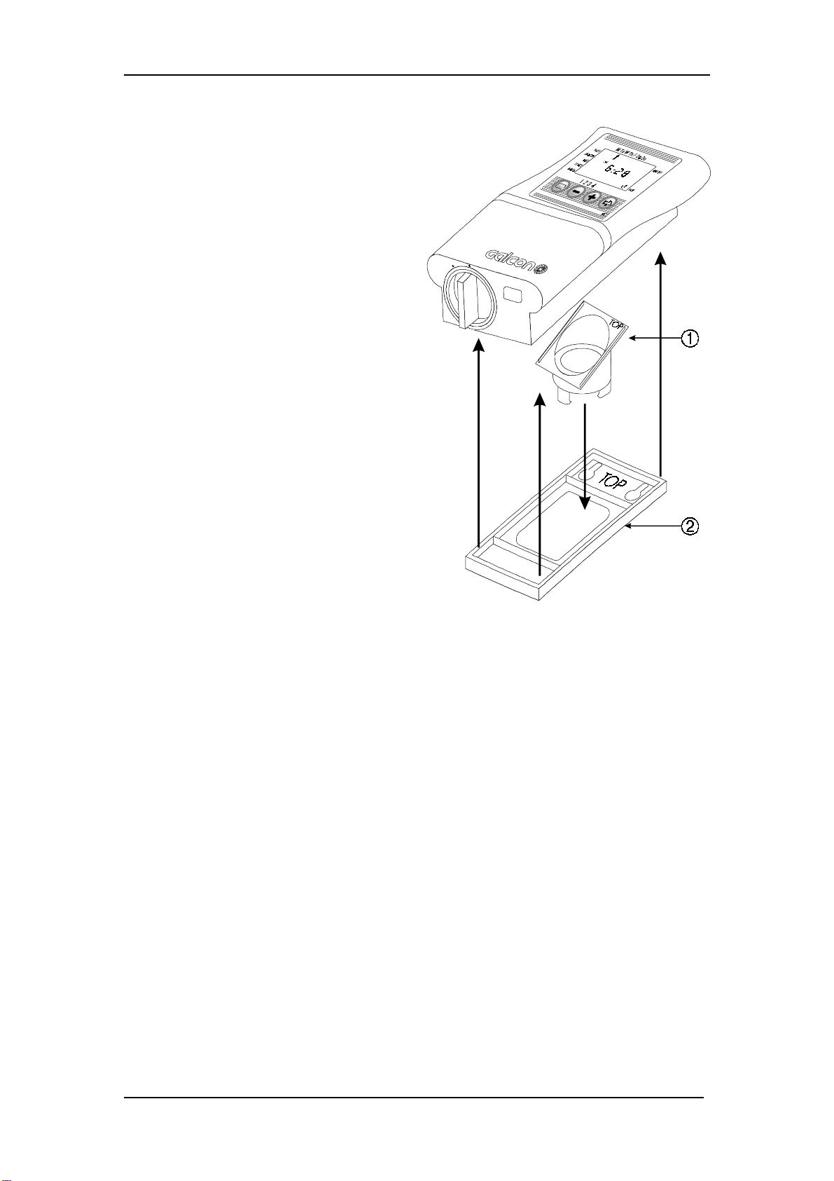
2. 1. Valve and Solenoid Assembly..........................................................3
2. 2. Manual-Mechanical Operation..........................................................4
2. 3. Battery Installation ...........................................................................4
2. 4. Installing the Controller In the Irrigation System...............................5
2. 5. Wiring the Solenoid and the Sensor.................................................6
3. Programming the Irrigation Controller............................................9
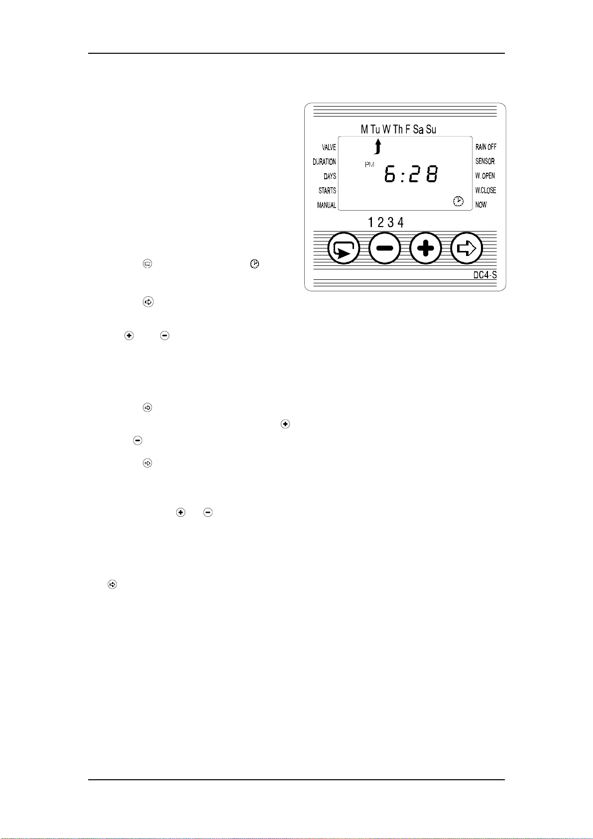
3. 1. Setting the Current Time and Day of the Week...............................10
3. 2. Valve Selection (Model DC4S only)...............................................11
3. 3. Setting the Irrigation Period............................................................11
3. 4. Selecting Irrigation Days of the Week.............................................12
3. 5. Setting Irrigation Start Times..........................................................13
3. 6. Example: Programming A Weekly Irrigation Schedule....................14
4. Additional Programming Options...................................................15
4. 1. One-Time Irrigation........................................................................15
4. 2. Cyclical Irrigation...........................................................................15
4. 3. Setting Day of the Week and Time For Cyclical and One-Time
Irrigation ........................................................................................16
4. 4. Example: Programming A Cyclical Irrigation Schedule...................17
4. 5. “Manual” Irrigation System Operation Via the Irrigation Controller18
4. 6. Irrigation Controller Suspension .....................................................19
4. 7. Program Lockout Sensor ................................................................19
4. 8. Irrigation Window In the Cyclical Program Mode...........................21
5. Additional Displays..........................................................................23
5. 1. Valve Wait Mode (Models DC4S only)..........................................23
5. 2. Blinking Low Battery Warning.......................................................23
5. 3. Constant Low Battery Warning.......................................................24
5. 4. Missing Program Data....................................................................24
5. 5. Sensor Lockout of the “Manual” Irrigation Program.......................25
6. Maintenance .....................................................................................26
7. Troubleshooting and Solutions Table..............................................26
8. Additional Accessories.....................................................................27

Parts Identification
3
1. Parts Identification
1. Top Cover
2. Controller Display
3. Bottom Cover
4. Battery Compartment Cover
5. Solenoid
6. Drainage Openning
7. Valve Handle (Orange)
8. Bayonet
9. Water Flow Direction Arrow
10. Hydraulic Valve
Figure 1
Before installation: make sure a filter is installed upstream to the
valve. (See list of additional accessories page 27.)
2. Setting Up the Irrigation Controller
2. 1. Valve and Solenoid Assembly
1. Shut the main irrigation system valve.
2. Before installing the hydraulic valve
[5] in the irrigation system, remove the
solenoid [1] from the valve with a 90°
counter-clockwise turn. Be careful not
to loose the seal (O-ring) [3].
3. Install the hydraulic valve in the
irrigation system, paying attention to
the correct water flow direction, as
indicated by the arrow [4] on the valve
cover.
Figure 2
5. After installing the hydraulic valve [5], assemble the solenoid with a 90°
clockwise turn. Be sure to place the seal (O-ring) [3] in its proper
location.
Note: A small amount of water is expelled from the drainage opening on the
solenoid during valve activation (manual or automatic).

Setting Up the Irrigation Controller
4
2. 2. Manual-Mechanical Operation
The irrigation valve can be opened
and closed independent of controller
operation. Manual operation is
useful when immediate irrigation is
required, without the delay of
controller programming.
The 3-position valve handle [A] is
located on the solenoid Manual
valve, and functions as follows:
Closed [1], Automatic Operation
[AUTO], Open [2]. Note that the
Open and Closed positions in
2-Way and 3-Way valves are
reversed (see drawing below).
* Figure 3
* 2-Way Valve 3-Way Valve
Important! For automatic irrigation operation, the valve handle must be in
the middle (AUTO) position.
2. 3. Battery Installation
Rotate the battery compartment
cover handle to the 11 o’clock
position to remove the cover. Insert
batteries (see drawing). All
controller display elements will
briefly appear on the display,
followed by the blinking time
“12:00”. The controller is now
ready to be programmed.
Important! Make sure to replace the battery compartment cover with its
handle in the 11 o’clock position to avoid possible cover guide pin
breakage.

Setting Up the Irrigation Controller
5
2. 4. Installing the Controller In the Irrigation System
If the mounting plate [2] is attached
to the controller, remove it.
1. Insert the mounting coupling [1]
into the mounting plate, aligning
the words “TOP”, which are
stamped on both the coupling,
and the plate (see Fig. 4).
2. Press the mounting plate, with
the mounting coupling inserted,
against the irrigation controller
back.
* The controller mounting plate [2]
can be mounted on a wall using
two screws, in which case
mounting coupling [1] is not
used. The distance between the
controller and the solenoid is
limited by the length of their
connecting cable.
Figure 4

Setting Up the Irrigation Controller
6
2. 5. Wiring the Solenoid and the Sensor
2. 5. 1. Model DC1S–6051 WP
solenoid wires are permanently connected to the irrigation controller. This
model includes no connection block nor sensor option.
2. 5. 2. Models DC1S–6051 SN, DC4S–6054 SN
1. Remove the bottom cover [1] from the irrigation controller.
2. Connect the solenoid cables to the connection block [2]:
A three-wire cable (white, red and black) emerges from each solenoid.
Connect the White solenoid wire leads (W) to connection “C” on the
connection block.
3. Connect the Red and Black wire leads from each individual solenoid to
its corresponding valve position on the connection block (R=Red wire,
B=Black wire), where each Red and Black wire pair is connected to

Setting Up the Irrigation Controller
7
the valve number marked. Valve numbers are marked: V1 = first valve,
V2 = second valve, etc.
4. Connect the program lockout sensor (option): Connect the sensor wires
to the connection block positions marked SNSR [3] in any order.
2. 5. 3. Models DC4S–6054 WP, DC1S–6051 WP SN, DC4S–6054 WP
Four of the cables exiting from the controller(1) are the same color and
are marked 1 through 4 . The fifth cable is not marked. The end of each
cable is protected by a plastic covering that must be removed prior to
connection. Cables 1 through 4 should be connected to the four
electrically operated valves (3) and the fifth cable, to the sensor (4).
The controller and its connections are waterproof. In order to maintain the
waterproofing, it is important to ensure the following:
* Do not remove protective coverings from cables that are not connected
to a valve. Exposed cable ends can short-circuit between themselves or
with other conductors.
* The controller cable connections to the valve cables (3) are made using
special waterproof connectors (2) which are included with the product.
See illustration.
1. Cut the plastic protective covering from the controller cables (1) near
the point of their connection. The solenoid cables have three wires:
white, red and black. Strip 3-4 cm of the outer insulation. Do NOT
strip the wires themselves. If the wires' leads are exposed, cut them to
the colored insulation. METAL LEADS SHOULD NOT BE
INSERTED INTO THE WATERPROOF CONNECTOR.

Setting Up the Irrigation Controller
8
2. Connect each of the wires to the waterproof connector (2).
3. Three wires exit from each of the solenoids: white, red and black.
Connect the white wire of the solenoid to the connector to which you
connected the white wire from the controller. Press the center disc
firmly towards the wires until its surface aligns with the connector's
perimeter. Connect the red and black wires according to the same
principle. Refer to the diagram.
4. Connect the remaining controller cables to the solenoid cables
according to the number of valves in the system. Make sure that the
valve numbers correspond with the numbers on the cables from the
controller.
Sensor connection (optional): The sensor is connected to the additional,
unmarked cable. This cable contains only two wires and should be
connected using a waterproof connection, as described
Important: Do not program a valve which is not in use or is not
connected using a waterproof connection.

Programming Options
9
3. Programming the Irrigation Controller
This section details programming steps for a simple irrigation program.
The following section deals with more advanced irrigation controller
applications.
The Computerized Irrigation Controller is programmed with the aid of 4
buttons:
Programming Step Selector - used to select the desired programming
mode
(e.g., clock setting mode)
Parameter Selection Button - used to select the parameter to be
changed (e.g.,
hour, minute, etc.). Only a blinking parameter can be changed.
Data Increment Button (Increase) - raises the value of the selected
parameter
(e.g., when hours selected, from 06:00 to 07:00).
Data Decrement Button (Decrease) - lowers the value of the
selected
parameter (e.g., when hours selected, from 06:00 to 05:00).

Programming Options
10
3. 1. Setting the Current Time and Day of the Week
To enable the irrigation controller to
operate the irrigation system at the
desired times, the current time and
day of the week must be set. The
following steps explain how to set
the day and time, as well as
installing the irrigation controller
and its accessories in the irrigation
system.
1. Press a few times until
appears.
2. Press . The hour digits blink.
Set the current hour with the aid
of and
(Note: AM and PM designations
appear to the left of the hour
digits).
3. Press . The minute digits blink.
Set the minutes with the aid of
and
4. Press . A blinking up arrow
appears at the top of the display.
Set the current day of the week
by pressing or .
* Display digits will stop blinking
after 10 seconds. If the last data
item has stopped blinking, press
to continue the programming
process.

Programming Options
11
3. 2. Valve Selection (Model
DC4S only)
This model operates from 1-4
valves, each independently
programmed. Select the desired
valve, then continue with the
irrigation program as detailed.
1. Press until appears.
2. Press . A blinking arrow
appears at the bottom of the
display.
3. Move the arrow to select the
desired valve number by
pressing or .
4. Press to go to the next step.
3. 3. Setting the Irrigation Period
This setting determines the length of
time that the valve will remain open.
1. Press until appears.
2. Press . The hour digits blink.
Press again - the minute digits
blink.
Press again - the seconds
digits blink.
Set the desired irrigation period
by pressing and .
3. Press to go to the next step.
* Note: The irrigation period
seconds display
increases/decreases in 5 second
increments.

Programming Options
12
3. 4. Selecting Irrigation Days of the Week
This setting determines on which
days of the week the irrigation
controller will operate the valve
being programmed.
1. Press until appears.
2. Press . A blinking appears at
the top of the display, under
Monday.
3. Select the desired day of the
week by pressing .
4. Selecting/adding irrigation
days:
Press . The arrow under the
selected day will stop blinking.
The blinking arrow will move
one position to the right, to
appear at the next day of the
week. Select additional days of
the week in the same manner.
5. Canceling Scheduled
Irrigation Days:
Press . The arrow under the
selected day will disappear. The
blinking arrow will move one
position to the right, to appear at
the next day of the week. Cancel
additional scheduled irrigation
days in the same manner.
6.Press to go to the next
step.
* When the blinking arrow is
under Sunday, the next pressing
of shows in the center,
and a symbol at the right top
corner, of the display. To return
to "Selecting/adding irrigation
days" mode, press again.

Programming Options
13
3. 5. Setting Irrigation Start Times
In this step, up to 4 separate
irrigation start times can be
programmed during the selected day
for the valve being programmed.
The selected valve will open at each
of the start times set, for the
irrigation period as set in Section
3.3.
1. Press .until [1 ] appears. The
word or the last operation
time entered will appear on the
display.
2. Press . The displayed data will
blink ( or last operation time
entered).
3. Set the desired start with the aid
of
and . (Note: AM and PM
designation appears to the left of
the hour digits). Repeat this
process to set start times 2, 3
and 4, as required.
4.To cancel a given start time,
select it by pressing . Next,
press . The hour digits will
blink.
5. Press or until the word
appears on the display. Go to
step 7.
6. Models DC4 only:
Press until appears. Select
another valve according to
Section 3.2, "Valve Selection"
and repeat steps 1-3 to program
operation times for the valves
selected.
7.Press to go to the next step
(Section 4.5, “Manual” Irrigation
System Operation". Press 3
times to return to the main screen
(clock).

Programming Options
14
3. 6. Example: Programming A Weekly Irrigation Schedule
Let’s assume that we want to program the irrigation controller to water
three times a day:
at 8:00 AM, 1:00 PM and 7:00 PM, for 2½ hours each time, on Monday
and Thursday.
If you are using a Model DC1s irrigation controller, go to step 4.
1. Press until appears.
2. Press . A blinking arrow will appear at the bottom of the display.
3. Press or to move the arrow to select the number of valve to be
programmed.
4. Press until appears.
5. Press . The hour digits blink. Press or until the hour digit displays
2.
Press . The minutes digits blink.
Press or until the minutes digits display 30.
6. Press . will appear.
7. Press . A blinking appears at the top of the display, under Sunday.
Press until the blinking arrow appears under Monday, then press .
The arrow under Monday will stop blinking and will move one position
to the right, to Tuesday.
Press twice to bring the arrow to Thursday, then press .
8. Press . (Start time) [1 ] appears.
Press . The hours digits blink.
9. Set the start time to 8:00 AM by pressing or .
(Note: AM and PM designations appear to the left of the hour
digits.)
Repeat this step to set start time [ 2] to 1:00 PM and start time [ 3]
to 7:00 PM.
10.Press . (Start time) [ 4] appears.
Press . The hours digits blink.
11.Press or until appears. Start time 4 is canceled.

Programming Options
15
4. Additional Programming Options
4. 1. One-Time Irrigation
This option is used to program the
irrigation controller to operate the
irrigation system one time only, for the
irrigation period as set in Section 3.3.
1. Press until appears.
2. Press a number of times (for all
the days of the week) until
appears, and blinks on the
display.
3. Go to Section 4.3 to set the start
time day and time.
4. 2. Cyclical Irrigation
This option is used to program the
irrigation controller to operate the
irrigation system in a cyclical manner,
once every xminutes, hours or days,
for the irrigation period as set in
Section 3.3.
1. Press until appears.
2. Press a number of times (for all
the days of the week) until
appears, and blinks on the
display.
3.With the display blinking, press
or . The word “every” appears on
the display. The number of hours
and minutes in the cycle period
appear below the word “enter”.
4. Set the desired irrigation operation
frequency in minutes, hours or days
by pressing or -first minutes,
next hours and then days.
* When the irrigation operation
frequency exceeds 23 hours, the
word “days” appears, above
which the number of days
between irrigation operations
appears. For example, if the
irrigation operation frequency is
2 days, irrigation will take place
once every two days, for the set
irrigation period.

Programming Options
16
4. 3. Setting Day of the Week and Time For Cyclical and
One-Time Irrigation
These options are used to pre-set
the valve opening time. The number
of days until valve opening appears
on the display, to the right of the
irrigation start time (above the word
“days”). 0 days = program starts
today; where 1 = program starts
tomorrow, etc. (up to 30 days).
1. Press until [1 ] appears. The
last opening time entered
appears on the display.
2. Press . The hours digits blink.
3. Set the desired opening time by
pressing or (Note: AM and
PM designations appear to the
left of the hour digits.)
4. Press until the digit to the
right of the opening time blinks
(The digit above the word
“days”).
5. Set the number of days until
valve opening by pressing or
.
6. Press 3 times to return to the
main screen (clock).
* Valve openings 2, 3 and 4 are
canceled in this mode.

Programming Options
17
4. 4. Example: Programming A Cyclical Irrigation Schedule
Let’s assume that we want to program the irrigation controller to open the
valve at 12:45 PM, for a period of one hour, once every 5 days.
1. Set the irrigation period as in Section 3.3, Setting the Irrigation Period
(Press until appears, then set the desired irrigation period by
pressing and ).
2. Press until appears.
3. Press a number of times (for all the days of the week) until
appears, blinking on the display.
4. While the display blinks, press or . The display reads every
X:XY, where X:XY is the irrigation operation frequency in hours and
minutes.
5. Press until the hours and minutes displays disappear, and the word
“days” appears with a number above. Press until the number of days
changes to 5.
6. Press . [1 ] appears.
7. Press . The hours digits blink.
8. Press until the hours digits change to 12 (PM).
9. Press . The minutes digits blink.
10.Press until the minutes digits change to 45.

Programming Options
18
4. 5. “Manual” Irrigation System Operation Via the Irrigation
Controller
This option operates the selected
valve for the defined irrigation period.
The valve will automatically close at
the end of the irrigation period. Note
that the originally programmed
irrigation schedule continues to
function at the times set.
1. DC4S models only: Press until
appears. Select one or more
valves according to Section 3.2,
"Valve Selection".
2. Press until appears.
3. Press to open the valve. The
word On
is displayed.
4.Press to close the valve.
appears on the display.

Programming Options
19
4. 6. Irrigation Controller Suspension
This option is used to temporarily
suspend irrigation controller
operation. For example, while it is
raining. The irrigation operation
schedule remains in the controller
memory, but is not implemented
until the suspension is canceled. The
suspension option disables ALL
valves connected to the irrigation
controller.
1. Press until appears.
2. Press . appears and replaces
the water sprinkler symbol in
paragraph 1, above.
Press to return irrigation
system control to the irrigation
controller.
disappears and the water
sprinkler symbol reappears.
* The word “rAin” will appear on
the display if an attempt is made
to operate a previously
scheduled valve opening while
the irrigation controller is
suspended.
4. 7. Program Lockout Sensor
(This option is not included in model DC1S–6051 WP)
An advanced feature of the Irrigation Controller enables irrigation
monitoring using a lockout sensor. The lockout sensor contacts remained
closed as long as the pre-defined conditions do not exist. For example, if a
rain sensor is connected to the irrigation controller, irrigation takes place
as long as the sensor remains dry. If rain falls, the sensor prevents all valve
openings.
Each individual valve can be operated in conjunction with the sensor. To
associate the sensor to a particular valve(s), select the desired valve(s) and
activate the sensor (see the explanation below).

Programming Options
20
(To connect the sensor to the connection block - see Section 2.5,
"Wiring the Solenoid and the Sensor")
1. Select the valve to which the
sensor is to be associated
(Models DC4S only).
2. Press until appears next to
SENSOR.
3. Press to activate the sensor in
the irrigation program for the
selected valve.
* With the sensor circuit closed
(i.e., the sensor detects the
existence of a defined program
lockout condition) the symbol
blinks on the display. In this
situation, irrigation will not take
place through valves associated
with the sensor.
4.Press to disable the sensor.
The word “OFF” appears on the
display.
This manual suits for next models
4
Table of contents
Other Galcon Irrigation System manuals