Galebreaker Electric Maxidoor User manual

Electric Maxidoor®
Installation
Instructions
ENG

ELECTRIC MAXIDOOR®Overview
_______________________________________________________________________________________________
2 of 40
Figure 1
Additional Top
Support, see
Figure 2

ELECTRIC MAXIDOOR®Introduction
3 of 40
ENG
INTRODUCTION
Table 1: Parts List for Main Door
* Quantity according to size of door
Additional Top Support
Doors over 10m wide are supplied with extra support(s) for the panel and lifting
cable (Figure 2).
Figure 2
FIGURE 1
REF:
QTY
DESCRIPTION
A1
1
Door Panel
B1
1
Electric Drive with Control Box, Power Lead, Manual Override
Chain (Not Shown) and Three Push-Button Switch (3PB)
C1
1
Counterweight Mounting Plate
D1
2
Counterweights
E1
2
Counterweight Containment Boxes with Micro-Switches
F1
*
Intermediate Trolleys with 2no. PVC Pads & Fixing Bolts
G1
1
Right Lower Trolley with 2no. PVC Pads & Fixing Bolts
G2
1
Left Lower Trolley with 2no. PVC Pads & Fixing Bolts
H1
1
Right-Hand Top Plate Assembly
H2
1
Left-Hand Top Plate Assembly
I1
1
Reel 4mm Stainless Steel Cable (Not Shown)
I2
4
5mm Cable Grips to fix Cable to Lower Trolley (Not Shown)
J1
8
M8 x 30 Bolts to Secure Top Plate Assembly to Building (Not
Shown)
K1
4
M10 x 50 Bolts to Secure Drive and Counterweight Mounting
Plates to Brackets (Not Shown)
L1
1
Chain Keep
M1
2
M6 x 65 Bolts to Secure Chain Keep to Building (Not Shown)
SB1
SA1
SH1
SG1
SF1
SE1
SD1
SC1
SJ1
SI1

ELECTRIC MAXIDOOR®Introduction
4 of 40
ENG
Table 2: Parts List for Additional Top Support
FIGURE 1
REF:
QTY FOR
DOORS
10M -> 14.9M
QTY FOR
DOORS
15M -> 20M
DESCRIPTION
SA1
1
2
50mm Ratchet
SB1
1
2
Ratchet Bracket
SC1
1
2
M12 x 90 Bolt
SD1
1
2
50mm x 4m Webbing
SE1
4
8
85 x 85mm Clamp Plates
SF1
1
2
Wire Support Assembly
SG1
1
2
Wire Support Protection Pad
SH1
4
8
12 x 20mm Spacer
SI1
4
8
M8 x 20 Bolt
SJ1
4
8
M8 x 50 Bolt
SK1
3
6
M8 x 40 Bolts to fix Ratchet
Bracket (not shown)#
#Alternative M8 fastenings required if fixing onto wood or concrete.
Description
The Electric Maxidoor®is a power operated vertically moving folding door designed
for building access requirements.
Optional Pelmet
If your door has been supplied with a Pelmet, see Appendix 1 for the Parts List and
Installation Instructions. Note the Pelmet needs to be installed before the door.
Your Safety
The installation of the door panel is not recommended at excessive wind speeds as
it could damage the curtain or injure the Installer.
Pre-Installation Check
For structural requirements refer to attached Maxidoor®Pre-Installation Instructions,
these Installation Instructions assume all preliminary work has been completed
Right or Left Hand Drive
Your door will be supplied in accordance with the drive orientation specified when
ordered. The images and text in these Instructions are based on a door with a right-
hand drive, if you have ordered a left-hand drive then reverse the references. It is

ELECTRIC MAXIDOOR®Introduction
5 of 40
ENG
possible to change drive orientation on-site, please contact Head Office for further
information.
Installer Competence
The installer should be able to demonstrate the required level of competence via
evidence of installing similar products or formal training. If competence cannot be
proven then they should not be allowed to install the product.
Optional Adjacent doors with both drives on the extreme Left or Right
If this option has been ordered (Figure 3) then the door nearest the pair of drives is
to be installed first using these instructions, with the exception of a small variation
related to Section 3.4. The furthest door is to be installed second and has changes
relevant to Section 2.1, 2.2, 3.3, 6.2 and 6.3.Details of all variations are detailed in
Appendix 2.
Figure 3

ELECTRIC MAXIDOOR®Introduction
6 of 40
ENG
Electrics
Only allow qualified electricians to work on the electrical connections of the door.
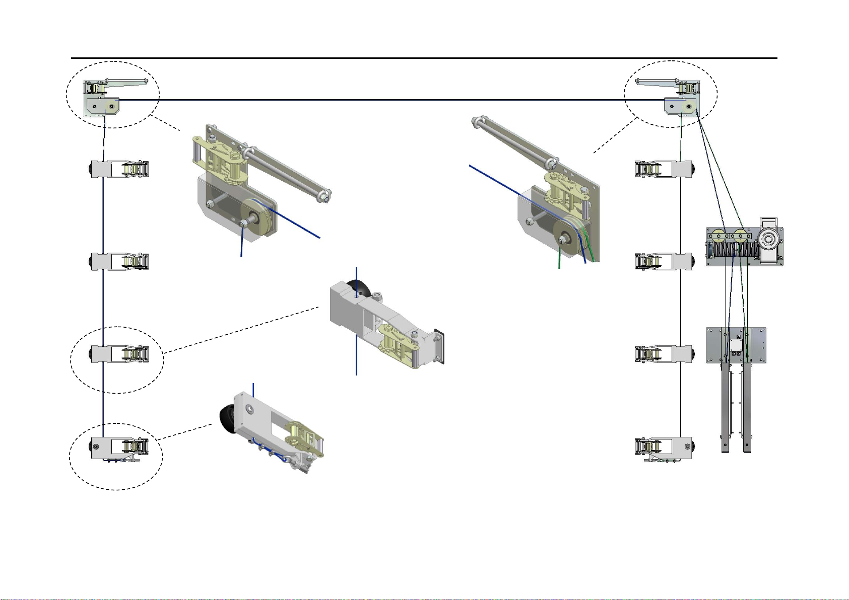
This document covers the key instructions with regards to bringing the Electric Drive
into service. Read the additional information from the supplier of the Electrical
Motor and Control Box for full installation instructions.
Items Required by Installer
Two personnel with a standard tool kit including:
•Allen key set: 3mm to 8mm
•8mm socket or spanner for Cable Grips
•Electric drill
•Wire cutters and self adhesive PVC tape
•Sharp pair of scissors or knife
•Spirit level
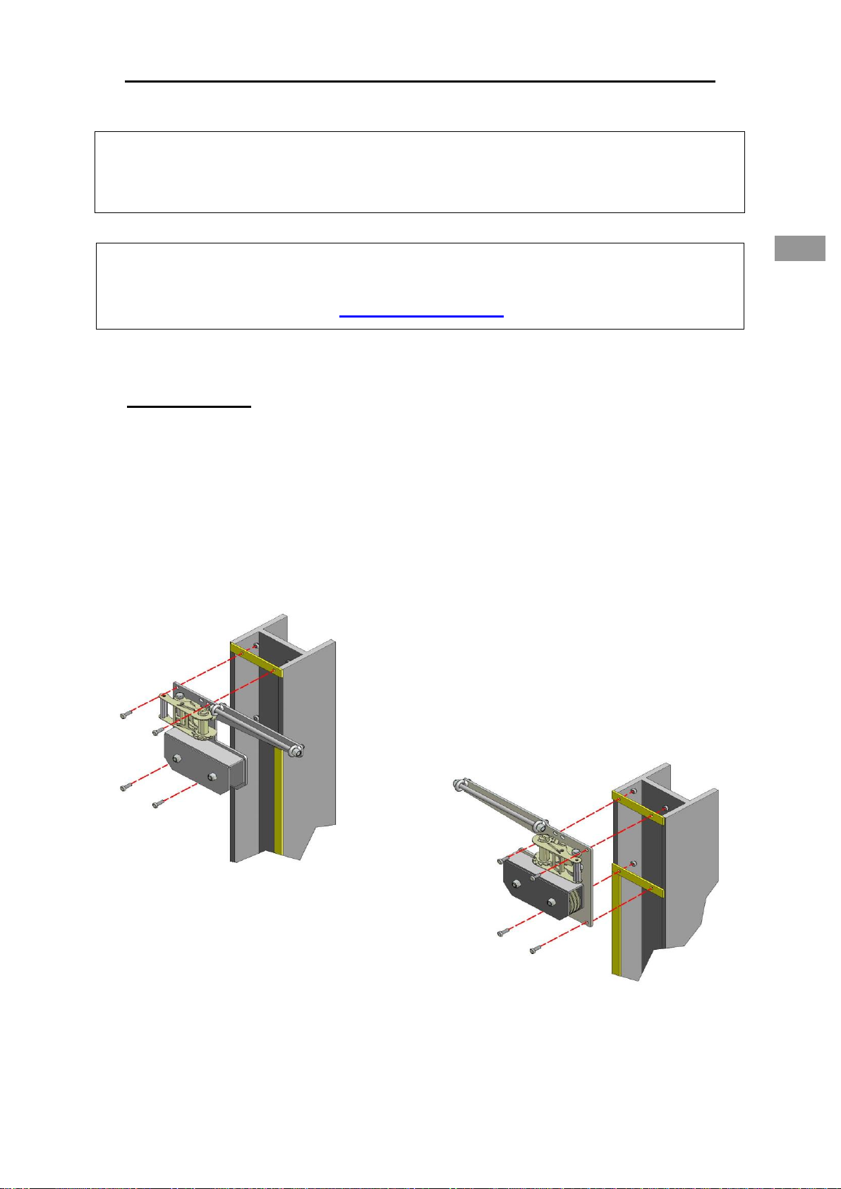
•M10 Bolts for fixing Electric Drive and Counterweight Plates to Brackets up to
30mm thick are supplied.
•M6 Bolts for fixing Chain Keep to Brackets up to 30mm thick are supplied.
•Two packers for Trolleys, 150mm to 250mm tall (wood, brick etc.)
•Boom or Scissor lift to reach top of opening
•Power supply with LOCKABLE isolator within 1m of the Electric Drive.
Single Phase = 230V, 750W, 5.2 Amps
Three Phase = 400V, 1500W, 3.2 Amps
•Clips to fix Electric Wires to the Building
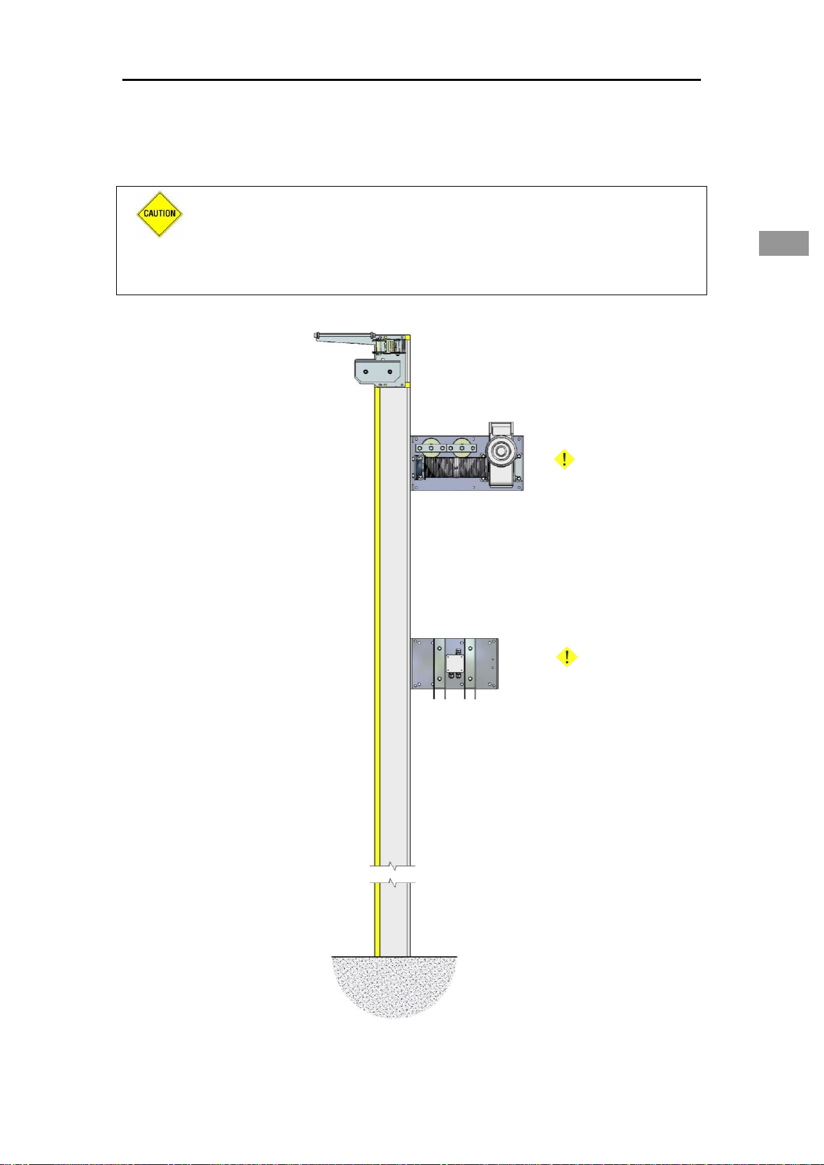
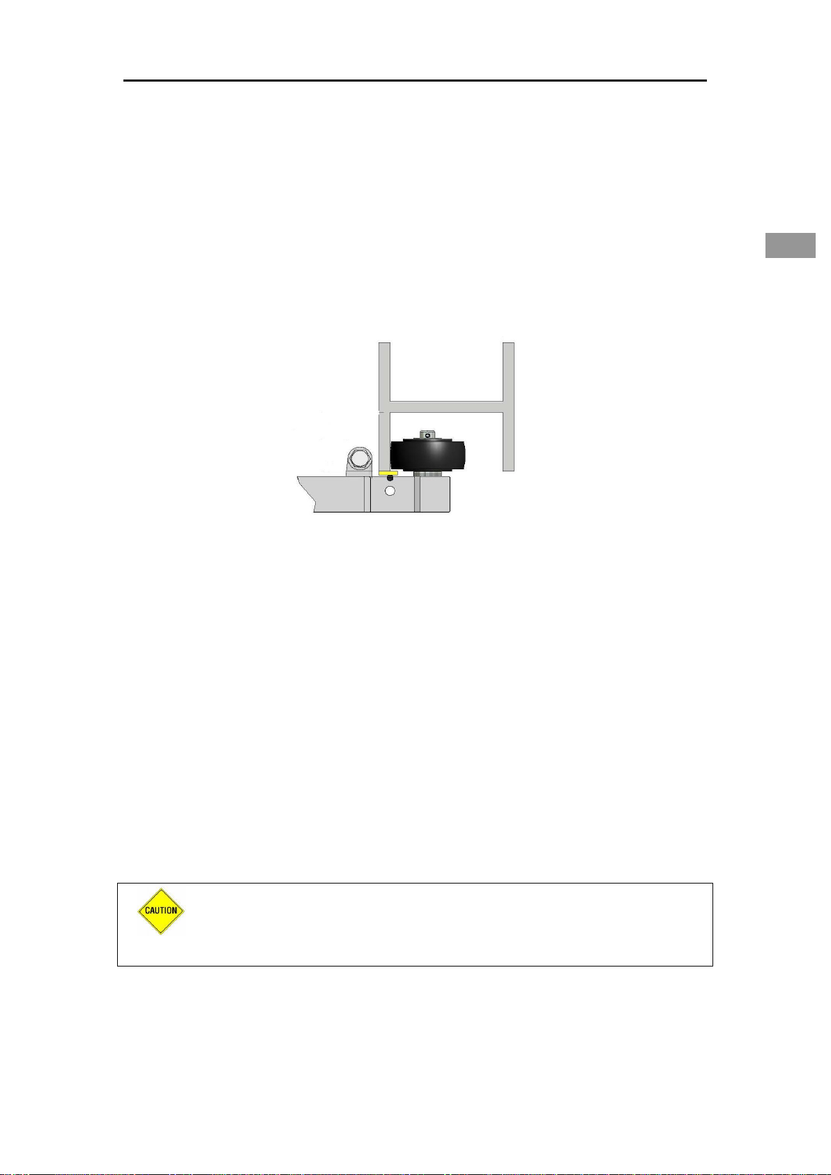
Key Instructions
CAUTION: Potentially hazardous situation: must be avoided otherwise
injuries may result.
ATTENTION: Observe the given instructions otherwise the product or
adjacent items may be damaged
NOTE: Helpful comments and information to assist in installation or use of your
product

ELECTRIC MAXIDOOR®Top Plates and Drive
7 of 40
ENG
NOTE: Before starting the installation you must fully read these instructions
(including the separate electrical details) to completely understand the procedure.
Keep the instructions supplied for reference purposes.
INSTALLATION
1. Optional Pelmet: If supplied, the Pelmet needs to be installed at this
stage before commencing on the door, see Appendix 1 for details
2. Installing Top Plates and Drive
2.1 Top Plate Assembly: Bolt the Top Plates (H1 and H2) to the pre-
installed brackets on the tracking top with the eight M8 x 30 bolts supplied
(Figure 4)
Figure 4
NOTE: Colour versions of the installation instructions can be downloaded from our
website:
www.galebreaker.com

ELECTRIC MAXIDOOR®Top Plates and Drive
8 of 40
ENG
350 Kg
350 Kg
2.2 Bolt Electric Drive (B1) and Counterweight Plate (C1) onto pre-
prepared brackets using the M10 Bolts supplied (Figure 5).
CAUTION:Ensure all fastenings detailed in section 2.1 through to
2.2 are secure and the fixing surface can withstand up to 350kg.
Failure of these fixings could result in the door falling off the
building, potentially injuring operators and bystanders
Figure 5

ELECTRIC MAXIDOOR®Trolleys and Lifting Cable
9 of 40
ENG
3. Installing Trolleys and Lifting Cable
3.1. Place packer (wood, brick etc.), 150mm to 250mm tall at the base of
the tracking. Locate Trolleys onto Tracking with the wheel behind the
retaining lip, Figure 6. Ensure the Lower Trolleys (G1 and G2) go on the
bottom with the eyebolt facing down and that there are an equal number of
Intermediate Trolleys (F1), on either side. In total there should be two trolleys
for each webbing strap, excluding the upper one (which is fixed to the Top
Plates).
Figure 6
3.2 Preparation for inserting lifting cable:
•Ensure the adjusting eyebolt on the Lower Trolley is centrally
positioned Figure 7.1
•To prevent cable fraying, wrap PVC tape around cable before cutting
3.3 Thread cables (I1) as indicated in Figures 7 and 8. Starting at the
Lower Trolley wrap the cable around the adjusting eyebolt and secure with
two 5mm Cable Grips (supplied), ensure the bridge section of the grip is
against the cable under tension (Figure 9).
CAUTION: Ensure the Cable Grips are correctly used and fully
tightened. Failure could result in the door falling off the building,
potentially injuring operators and bystanders

ELECTRIC MAXIDOOR®Trolleys and Lifting Cable
10 of 40
Figure 7
Figure 7.1
Figure 7.3
Figure 7.4
Figure 7.2
RH
LH
RH
LH

ELECTRIC MAXIDOOR®Trolleys and Lifting Cable
11 of 40
ENG
Figure 8
Figure 9
LH
RH

ELECTRIC MAXIDOOR®Trolleys and Lifting Cable
12 of 40
ENG
3.4 Doors up to 10m wide:
Thread Cables through hole in Intermediate Trolleys (Figure 7.2), around the
pair of Top Plates (Figures 7.3 and 7.4). Pay particular attention to the Cable
routing on the right-hand Top Plate (Figure 7.4). Referring to Figure 8,
continue Cables around 100mm pulleys on the Electric Drive down through
Counterweight Plate, around Counterweights (D1) and back up to the Drive.
Ensure the Left and Right Cables are positioned as indicated.
Doors over 10m wide with Additional Top Support(s):
Follow the details above, but include the Wire Support Assembly(s) SF1 when
passing the Cable between the pair of Top Plates (Figure 10).
Figure 10
3.5 Attaching Lifting Cable to the Electric Drive: For safe operation of the
door, the lifting cable must pass around the grooved drum a minimum of three
times, to achieve this pass the cable 950mm beyond the drums centre-line
and cut to length. Secure end of cable into the 6mm hole located towards the
centre of the drum and secure in place with the socket set screws.

ELECTRIC MAXIDOOR®Trolleys and Lifting Cable
13 of 40
ENG
First: To Release
Motor Brake Pull
Lever Back and
Swivel Washer
Second: Lift
Hand Chain over
Chain-wheel
3.6 Repeat process for the other Cable, when both have been installed
operate the Electric Drive using the Manual Override Chain. To use the Chain
Override, first release the Motor brake before lifting the Hand Chain over the
Chain-Wheel as shown in Figure 11. Ensure:
•The Cables feed onto the front of the drum (Figures 8 and 12)
•The Cables follow the groove in the drum
Continue to operate the Drive until the two stacks of Trolleys begin to lift,
check they are level and adjust as necessary. Small adjustment can achieved
via the Lower Trolley adjusting eyebolt.
CAUTION: Ensure there are a minimum of three wraps of Lifting
Cable around the drum when the door is fully lowered. Failure could
result in the door falling off the building, potentially injuring
operators and bystanders
Normal Electric Drive Manual Override
Figure 11a
Motor
Brake
Engaged

ELECTRIC MAXIDOOR®Trolleys and Lifting Cable
14 of 40
ENG
Figure 11b
Install the chain keep to the building, the height of the chain keep depends
upon your installation (Figure 11b), but is typically 1.5m high.

ELECTRIC MAXIDOOR®Panel
15 of 40
ENG
M8 x 70 Bolts
3.7 Fit Counterweight Containment
Boxes (E1) onto Counterweight Plate
(C1) using the M8 x 70 Bolts that are
placed in the Counterweight Plate fixing
holes, see Figure 12.
Figure 12
4. Commissioning Electric Drive
4.1 Fix Control Box to building and connect power lead to isolator: The
Control Box is designed to be at the level of the Electric Drive and must be
fitted internally away from direct rainfall. Ensure the glands face down and
the wires form a drip loop beneath the Control Box. Clip wires to building.
4.2 Fix Three Push-Button Switch (3PB) to building at low level, which can
be installed either internally or externally. Ensure the glands face down and
the wires form a drip loop beneath the Switch. Clip wires to building.
CAUTION: For safety, the switch must be positioned in sight of
the door.

ELECTRIC MAXIDOOR®Panel
16 of 40
ENG
ATTENTION: For points 4.3 through to 4.7 read this information in
conjunction with the full installation instructions from the supplier
of the Electrical Motor and Control Box.
4.3 Mains Connection: Ensure the link wire in Terminal Block X19 is in
the correct location to match the type of mains supply
CAUTION: When the lid of the Control Box is removed there are
High Voltage contacts exposed.
4.4 Checking Direction of Operating Buttons:
Press the Open Button on the Control Box, if the stack of trolleys begin to lift
then proceed to next point. If the direction is opposite then follow the details
as outlined in Table 3.
Table 3: Changing Direction of Operating Buttons
TYPE
INSTRUCTIONS
230V Single Phase
Swap Location of wires U and V on X2
400V Three Phase
Swap Location of wires L1 and L2 on X1
4.5 Checking Direction of the 3PB: Press the 3PB to check it is
operating the same as the Control Box.
4.6 Checking Direction of Open and Closed Limit Switches: Move the
Green and White Cam on the Electric Drive so they are clear of the Limit
Switches. Press the Open Button to lift the stack of trolleys 1m, note the
direction of the Cam. Adjust the Cams so that they are just before the Open
and Closed limit switches, (the Green Cam is for the Open Direction and the
White Cam is for the Closed Direction). Press the Open and Close Button to
check that the limit switches are wired on the correct side, if the Electric Drive
does not stop when the limits are depressed by the Cams then swap wires 2
and 4 on Terminal Block X15 and repeat the test.

ELECTRIC MAXIDOOR®Panel
17 of 40
ENG
4.7 Wiring in the Counterweight Micro Switches: Following Figure 13
connect the Counterweight Containment Box (E1) Micro-Switches in series
with the Motor Closed Limits.
Route the wire to pass through the Junction Box located on the Counterweight
Plate (C1) and then into the two terminal strips in the Control Box that run to
connection 4 of terminal block X15 (remove the link wire).
Figure 13
Terminal
Strip 1
Terminal
Strip 2

ELECTRIC MAXIDOOR®Panel
18 of 40
ENG
5. Installing door panel
5.1 Orientation of door panel (A1): The webbing straps face towards the
outside and the top is identified by the two 400mm long x 40mm pockets
located at either end of the panel (Figure 14).
Figure 14
5.2 Lay the panel across the opening in preparation to fasten the webbing
straps to each Trolley. Working up from the bottom Trolley first, pass the
webbing strap around the nylon bushes on the Trolley pillar and back towards
ratchet tensioner. When the panel edge is approximately 150mm to 250mm
from Trolley pillar feed webbing strap through slot in ratchet barrel and
operate the handle (Figure 15). At this point do not let the Panel touch the
pillar. With the exception of the upper strap (which is fixed to the Top Plates)
repeat for all webbing straps, ensuring the Panel is central and applying equal
tensioning throughout.
ATTENTION: To ensure the ratchet functions correctly there must
be a minimum of 150mm webbing around the ratchet barrel for
secure & permanent tensioning of the panel.
ATTENTION: Overloading the ratchet barrel with webbing will
restrict the tension you can apply to the panel due to an increase in
friction and a decrease in leverage. To free surplus webbing pull
ratchet release catch on handle and open 180 degrees until ratchet
body is flat and pull on webbing strap.

ELECTRIC MAXIDOOR®Panel
19 of 40
ENG
150mm ->
250mm
Trolley Pillar
Figure 15
5.3 Operate the Electric Drive to fully lift the Panel (the Green Cam may
have to be adjusted to achieve this). Following the principles detailed in
section 5.2 fasten upper webbing strap into Ratchets on Top Plates and
tension (Figure 16). Ensuring the Panel is central; fully tension the ratchets
by hand until it is impossible to operate further. If the Panel material is being
drawn into Ratchet, Section 5.4 details how to trim the fabric, once the
adjustments have been made continue tensioning.
Feed the M12 x 300 threaded bar on the Top Plates though the 40mm
pocket (Figure 16), the pocket may have to be trimmed to fit.
ATTENTION: Tension Ratchets fully, lack of tension will cause
damage to the door Panel. Tension by hand only, use of levers
could damage the Ratchets.
Figure 16
Threaded
Bar

ELECTRIC MAXIDOOR®Panel
20 of 40
ENG
5.4 The Panel has been manufactured to suit the opening, however if
trimming is required use scissors / knife to remove the fabric either side of the
webbing strap, ensuring all corners have a radius (Figure 17). Always remove
surplus fabric, do not just cut either side of the webbing which allows a loose
flap to be generated. Do not remove the fabric off the back of the
webbing. We recommend a cautious approach to trimming as final
tensioning and adjustment is completed in section 5.5.
Figure 17
5.5 Using the Electric Drive fully lower the Panel (the Black Cam may have
to be adjusted to achieve this). Revisit each trolley and whilst ensuring the
system remains centralised operate the Ratchets to remove any wrinkles or
creases, apply further tension by hand until it is impossible to the operate the
Ratchets. Complete final trimming of the Panel as necessary.
5.6 Bolt each Trolley back to the screen as shown in Figure 18 (image has
fabric removed for clarity) using the M8 x 30 Bolts supplied. To allow the Bolt
to pass through the Panel cut a slot 15mm to 20mm long in the Fabric. Note
the webbing strap is placed between the two PVC Pads.
Figure 18
Radii
Table of contents