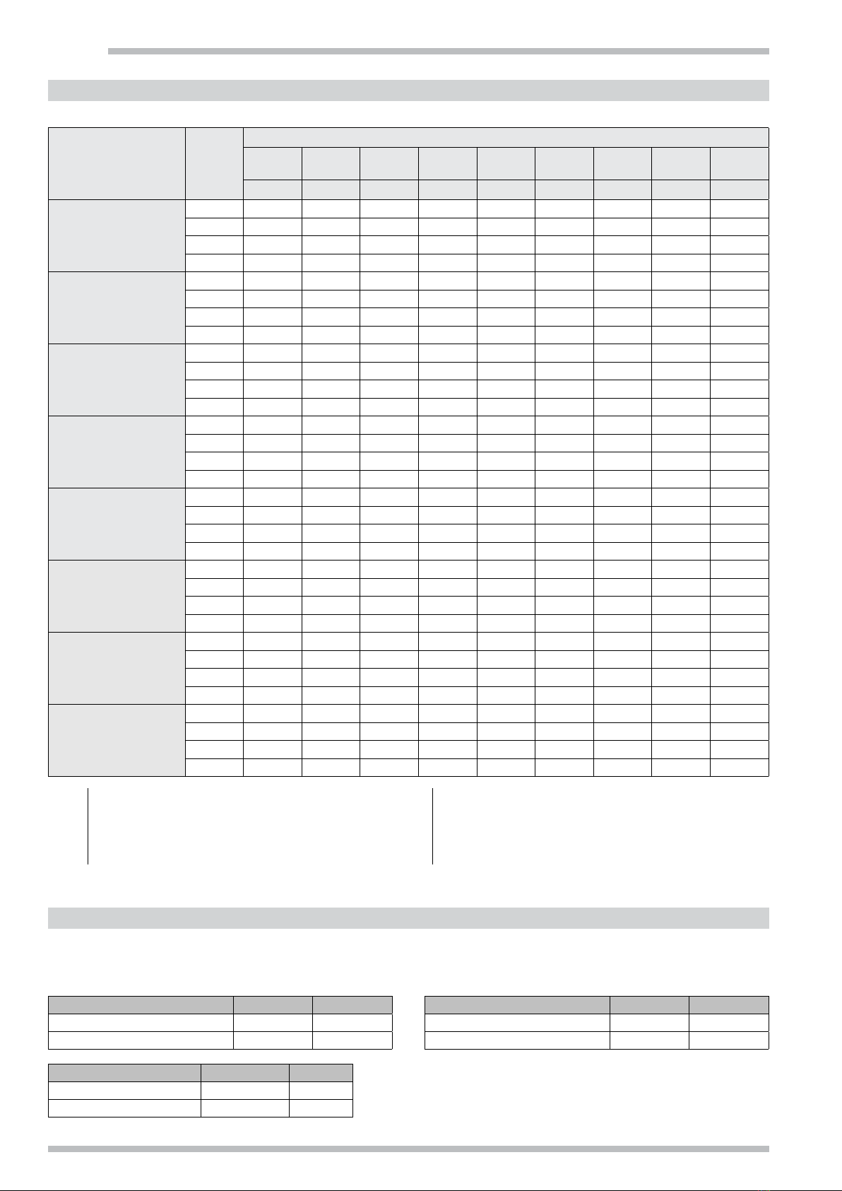
Galletti IWCi User manual

IWCi
CASSETTE FAN COILS WITH INVERTER
(2,6 kW - 9,9 kW)
TECHNICAL MANUAL
EN

IWCi
2It is strictly forbidden to reproduce this manual, even partially WC66000122 - Rev 03
1. PRODUCT CHARACTERISTICSCONTENTS
The technical and dimensional data provided in these documents is subject to
change based on improvements made to the product.
• To contact or notify the company, or for information:
• To learn the weight of each unit,
refer to the table in the Nominal Technical Data section
Galletti S.p.A. partakes in the
EUROVENT Certification Programme.
The products that are part of the programme can
be seen at: www.eurovent-certification.com
3-speed motor Brushless motor
t [h]
10
0 4 8 12 16 20 24
20
30
40
50
60
Lw [dB(A)]
TEMP. TREND WITH 3-SPEED MOTOR AND BRUSHLESS MOTOR
t [h]
18
4 8 12 16 20 24
19
20
21
22
23
Lw [dB(A)]
3-speed motor Brushless motorSet Point
NOISE TREND WITH 3-SPEED MOTOR AND BRUSHLESS MOTOR
With a solid thirty-years of experience in fan coil production, Galletti presents the
new IWCi brushless line.
Galletticassettes areequipped witha latestgeneration permanent magnet(brushless)
electric motor which, controlled by an inverter, makes it possible to continuously
varyfan rpm. Thegreat advantage of brushlessmotors is theconsiderable reduction
in electric draw, which can drop to 1/3 with instantaneous operation in comparison
to traditional motors, and with integrated operation it has been proven to drop to
50%, with a corresponding drop in CO2 emissions! The DC Inverter technology
makes it possible to continuously adjust the air flow rate to the actual needs of the
environment, considerably reducing fluctuations in the room temperature, which
is typical of step adjustments.
This directly leads to a drop in the fan coil sound emissions level, which now
adapts to the requests of the room.
1. PRODUCT CHARACTERISTICS ................................................................ 2
2. CONSTRUCTION CHARACTERISTICS ...................................................... 3
3. NOMINAL TECHNICAL CHARACTERISTICS ............................................. 5
4. PERFORMANCES .................................................................................... 7
5. SOUND LEVELS....................................................................................... 8
6. OVERALL FOOTPRINT ............................................................................. 8
7. CONNECTIONS ...................................................................................... 12
8. MODBUS PROTOCOL ............................................................................ 18
9. ELECTRICAL DIAGRAMS ....................................................................... 19
10. UNITS AND ACCESSORIES.................................................................... 23

H50rpm
∆T
H-
M
M-
L
L-
LL
LL-
1°C0 1,5°C 2°C
WC66000122 - Rev 03 It is strictly forbidden to reproduce this manual, even partially 3
LATEST GENERATION INVERTER MOTORS
“Moulded”permanentmagnet motors controlledby a specificallydeveloped inverter
represents the latest evolution in terms of efficiency (reduced consumption) and
precise fan speed control:
• excellent efficiency (even up to 98%);
• more compact solution;
• considerable reduction in electromagnetic disturbance;
• extended service life, beyond the best, traditional motors.
HUMIDITY SENSORS AND PERCEIVED TEMPERATURE
MANAGEMENT
One of a kind on the market, IWCi incorporates a relative humidity sensor inside its
particularly evolved electronics. The humidity sensor signal is used by the logic by
placing it in relation with the temperature measured by the room air and Humidex sensor,
which measures the perception of the human body considering the combined effects
of temperature and humidity. The implemented algorithm acts on the regulating logic,
modifying the target temperature based on the perceived temperature. The effect is
significant, especially in the summer (cooling mode), i.e. when the environment is very
hot and humid, and therefore needs to be cooled; nonetheless, the algorithm also works
when the cassette is in winter mode, in which case the correction is also imperceptible
because the real temperature and the perceived temperature tend to be the same.
NETWORK MANAGEMENT
The innovative communication system is designed to develop networks such as:
• SACBUSnetworks withconnectionto variousunits withindependentadjustment
and control over the operating mode and set points from a single station;
• MODBUS networks with unit management from external supervisor through
Modbus RTU protocol;
• MIXED networks with unit management provided by an external supervisor
through Modbus RTU protocol, and connection to the first and other units
through SACBUS network. Accordingly, the units networked with MODBUS
are controlled by the supervision system, and it is possible to associate other
units to each one of them, which replicate operation through SACBUS network.
IR REMOTE CONTROLLER, WHICH CAN ALSO BE USED AS A
WIRED CONTROLLER DEVICE
There is no distinction between the remote controller and the wired controller
versions: a single object can be used in remote controller or even wall-mounted
controller, by wiring it with a simple twisted pair setting up communication with
the control board on the cassette, and provides the power supply to the control
device itself (no power consumption or need to change batteries)
An infra-red controller device can also be used (with broad transmission range and
insensitive to the interference of fluorescent lights) can be used to control a single
cassette ("one to one" mode) or to control a group of cassettes ("cluster" mode).
If you choose to use an IR remote control, it is possible to configure the individual
remote control devices on 4 different communication frequencies so as to operate
distinctly on 4 different hydronic units.
THE I-FEEL FUNCTION
To provide a greater level of comfort and even more precise control, the user can
choose to base temperature control on a second air probe installed inside the
remote controller.
The correct position of the IR control is therefore essential for excellent operation
of the hydronic cassette.
If it is connected to a network and operating based on perceived temperature, it is
advisable to use the air probe on board the unit.
• Load bearing structure in galvanised steel sheet metal, lined inside and out to
ensure the thermal and acoustic insulation of the unit. The structure houses
the main parts (heat exchange coil, motor ventilation unit and condensation
discharge pump) and is set up for outdoor air intake and the air distribution
in an adjacent room;
• Dynamically and statically balanced backward curved centrifugal fan, fitted
directly to the electric motor, with vane profile designed for extremely silent
and efficient operation, even at a low rpm;
• 230V electric motor, with thermal protection on the coils, 4 speeds to optimise
unit performance in terms of noise and energy;
• High efficiency heat exchange coil with copper tube and aluminium fins,
complete with air relief valves;
• Plastic condensation collection basin, moulded directly inside the structure
of the Styrofoam air directing structure.
2. CONSTRUCTION FEATURES
SPEED SPLITTING
If you set a ventilation speed, it is possible to start using a "speed splitting" logic.
The logic limits the ventilation speed by a temperature close to the set point.
Accordingly, when the requested temperature is reached, the noise and absorption
of the hydronic cassette drop achieving, at the same time, more precise control.
OPERATING LIMITS
• Plumbing circuit:
- Minimum water inlet temperature: 4°C.
- Maximum water inlet temperature:
main coil: 70°C
secondary coil: 80°C
Note: For the comfort level (i.e. an even air temperature in the
room), we recommend never exceeding 55°C for the water inlet
to the coil (maximum operating pressure of: 16 bar).
• Ambient air:
- Minimum air inlet temperature: 5°C
- Maximum air inlet temperature: 32°C
Warning: During downtime for installation, if there is a connection
to a fresh air intake or if the room temperature is close to 0°C,
the pipes run the risk of freezing. Set up a drain for the plumbing
circuit.

IWCi
Z
Y
X
4It is strictly forbidden to reproduce this manual, even partially WC66000122 - Rev 03
• Water level alarm
Note: During normal operation, the condensate pump is actuated at the
same time as the main exchanger valve.
In case of abnormal backflow of water into the condensate tank due to
a faulty pump, a dirty tank, or a plugged drain line,...), a safety contact
(floater) activates the pump on a permanent basis.
• Electrical parts housed in an external box, comprised of the electronic unit
management card and the pump operation relay. The box is set up next to the
hydraulic connections to reduce the need for technical installation spaces;
• Auxiliary basin to collect the condensation from the hydraulic connections
and valves;
• Intake and air delivery panel, made with Styrofoam, in RAL 9001, pre-moulded
high density expanded Styrofoam air routes complete with air intake grill
equipped with washable polypropylene filter, and adjustable air outlet fins.
This panel differs from the version equipped for wired controller, where fin
position control is carried out manually, as it is motorised in this case, with
infra-red ray remote controller. In addition, there is a series of leds on the front,
reporting the unit operating status.
CONSTRUCTION VERSIONS
• cassette fan coils (2-pipe system), model 32 / 42 /52;
• cassette fan coils (4-pipe system), model 34 / 44.
AIR FLOW
• 45° fin inclination;
• Limit speed 0.2 m/s.
MODEL IWCi 32-34 IWCi 42-44 IWCi 52 IWCi 62 IWCi 82 IWCi 102
Speed 123412341234123412341234
Air Flow Z 1,7 3,0 3,7 3,9 1,6 3,1 3,9 4,5 2,4 3,6 4,3 5,0 2,6 3,3 4,0 4,6 2,7 3,6 4,5 5,2 2,8 3,8 5,1 5,8
Height Y 1,2 2,0 2,5 2,6 1,1 2,0 2,7 3,0 1,5 2,3 2,8 3,2 1,6 2,0 2,5 2,8 1,7 2,2 2,6 3,1 1,8 2,4 3,1 3,6
Distance X 1,3 2,3 2,7 2,9 1,2 2,2 3,0 3,4 1,8 2,7 3,2 3,6 2,1 2,6 3,2 3,7 2,1 2,8 3,4 4,0 2,2 3,0 4,0 4,6

WC66000122 - Rev 03 It is strictly forbidden to reproduce this manual, even partially 5
3. NOMINAL TECHNICAL CHARACTERISTICS
1Water temperature 7/12°C, D.B. air temperature 27°C, W.B. 19°C, 47%
humidity
2Inlet water temperature 50°C, water flow rate during operation in cooling,
air temperature 20°C
3Water temperature 70/60°C, air temperature 20°C
4Sound power in compliance with ISO 3741 and ISO 3742
5Sound pressure measured for a distance of 1 m, directionality factor of 4
NOMINAL TECHNICAL CHARACTERISTICS FOR IWCi FAN COILS, MODELS WITH 1 COIL
MODEL 32 42 52
Speed 123412341234
Total cooling output (1) kW 1,24 2,15 2,35 2,60 1,70 3,50 4,00 4,60 2,47 3,80 4,42 5,06
Sensitive cooling output (1) kW 0,91 1,78 2,00 2,23 1,16 2,63 3,05 3,56 1,84 2,97 3,51 4,04
Water flow rate (1) l/h 212 368 404 445 292 600 686 788 423 653 758 869
Load loss (1) kPa 3 8 9 11 3 11 14 17 7 14 18 23
Heating output (2) kW 1,54 2,83 3,11 3,49 1,87 4,35 4,85 5,70 3,35 5,33 6,14 6,75
Load loss (2) kPa 3 7 8 10 3 10 13 17 6 14 18 23
Heating output (3) kW 2,64 4,87 5,35 6,00 3,14 7,38 8,20 9,65 5,74 9,15 10,5 11,5
Water flow rate (3) l/h 232 427 469 527 275 648 719 847 504 803 924 1011
Load loss (3) kPa 3 9 10 12 2 11 13 18 8 19 24 28
Water content dm3 0,43 0,86 0,86
Air flow rate m3/h 180 400 460 520 200 530 630 750 370 630 760 880
Absorbed power W 5 10 13 15 8 24 28 36 12 34 40 47
Sound power (4) dB/A 30 41 44 46 32 48 51 55 41 53 57 61
Sound pressure (5) dB/A 25 36 39 41 27 43 46 50 36 48 52 56
Hydraulic connections inches 1/2 1/2 1/2
Unit dimensions H x W x D mm 273 x 575 x 575 273 x 575 x 575 273 x 575 x 575
Panel dimensions H x W x D mm 64 x 730 x 730 64 x 730 x 730 64 x 730 x 730
NOMINAL TECHNICAL CHARACTERISTICS FOR IWCi FAN COILS, MODELS WITH 1 COIL
MODEL 62 82 102
Speed 123412341234
Total cooling output (1) kW 4,20 5,00 5,42 6,00 5,50 6,50 8,00 9,10 6,24 8,09 8,90 9,92
Sensitive cooling output (1) kW 3,14 3,70 3,99 4,40 4,11 5,08 6,10 6,84 4,69 6,17 6,87 7,71
Water flow rate (1) l/h 721 859 930 1031 944 1116 1372 1561 1069 1389 1529 1702
Load loss (1) kPa 16 22 25 30 21 28 41 51 27 42 50 60
Heating output (2) kW 5,40 6,40 7,10 7,70 6,28 8,52 9,42 10,2 7,34 9,53 10,6 11,7
Load loss (2) kPa 16 21 25 30 20 27 39 48 26 42 49 60
Heating output (3) kW 9,2 10,9 12,1 13,1 10,5 14,4 15,8 17,0 12,3 16,0 17,8 19,6
Water flow rate (3) l/h 808 956 1063 1150 920 1267 1385 1491 1079 1403 1561 1721
Load loss (3) kPa 18 24 29 33 18 31 37 42 25 40 48 57
Water content dm3 1,00 1,50 1,50
Air flow rate m3/h 850 1060 1160 1300 830 1090 1270 1400 1200 1700 1980 2300
Absorbed power W - 20 25 41 - 22 41 55 - 36 43 64
Sound power (4) dB/A 43 48 49 51 37 46 50 53 43 49 53 57
Sound pressure (5) dB/A 38 43 44 46 32 41 45 48 38 44 48 52
Hydraulic connections inches 3/4 3/4 3/4
Unit dimensions H x W x D mm 262 x 760 x 760 292 x 1050 x 760 292 x 1050 x 760
Panel dimensions H x W x D mm 78 x 860 x 860 78 x 1150 x 860 78 x 1150 x 860

IWCi
6It is strictly forbidden to reproduce this manual, even partially WC66000122 - Rev 03
NOMINAL TECHNICAL CHARACTERISTICS FOR IWCi FAN COILS, MODELS WITH 2 COILS
MODEL 34 44
Speed 12341234
Total cooling output (1) kW 1,10 1,72 1,88 2,05 1,58 2,88 3,28 3,76
Sensitive cooling output (1) kW 0,83 1,51 1,66 1,82 1,10 2,27 2,60 3,00
Water flow rate (1) l/h 189 295 323 351 272 494 562 645
Load loss (1) kPa 4 8 9 11 4 11 13 17
Heating output (3) kW 1,10 1,78 1,95 2,20 1,48 2,87 3,14 3,76
Water flow rate (3) l/h 97 156 171 193 130 252 276 330
Load loss (3) kPa 11 25 29 36 7 22 26 36
Water content dm3 0,43 0,86
Air flow rate m3/h 180 400 460 520 200 530 630 750
Absorbed power W 5 10 13 15 8 24 28 36
Sound power (4) dB/A 30 41 44 46 32 48 51 55
Sound pressure (5) dB/A 25 36 39 41 27 43 46 50
Cold coil hydraulic fittings inches 1/2 1/2
Hot coil hydraulic fittings inches 1/2 1/2
Unit dimensions H x W x D mm 273 x 575 x 575 273 x 575 x 575
Panel dimensions H x W x D mm 64 x 730 x 730 64 x 730 x 730
1Water temperature 7/12°C, D.B. air temperature 27°C, W.B. 19°C, 47%
humidity
2Inlet water temperature 50°C, water flow rate during operation in cooling,
air temperature 20°C
3Water temperature 70/60°C, air temperature 20°C
4Sound power in compliance with ISO 3741 and ISO 3742
5Sound pressure measured for a distance of 1 m, directionality factor of 4

WC66000122 - Rev 03 It is strictly forbidden to reproduce this manual, even partially 7
4. PERFORMANCES
In order to define the performances of IWCi subject to conditions different from rated conditions, a computer program for the correct choice of the
units is provided by Galletti SpA.
With a few input data it will be possible to get information on the behaviour of an IWCi referring to the desired operating conditions.
It will be sufficient to enter the following data:
• Dry bulb inlet air temperature
• Wet bulb inlet air temperature or alternatively the relative humidity
• Inlet water temperature
• Outlet water temperature or alternatively the water flow
• Ethylene glycol percentage (default 0)
• Fan speed
• Available static head (default 0) and air flow rate (≠0)
• Directivity factor and distance
Output data
• Selected full scale (850-1450 RPM)
• Control voltage
• Total cooling / heating capacity
• Sensible cooling capacity
• Water flow
• Pressure drop, water side
• Outlet air temperature
• Sound power level
• Sound pressure level under the specified conditions
• Power input
The selection report generated by the software includes the drawing with overall dimensions and description of the unit.

IWCi
IWCi Vr
Lw
125 Hz 250 Hz 500 Hz 1000 Hz 2000 Hz 4000 Hz 8000 Hz LwA LpA
dB dB dB dB dB dB dB dB/A dB/A
IWCi O32
1 36,1 33,9 25,3 19,7 21,4 16,8 20,0 30,0 25,0
2 42,5 43,4 41,5 32,2 27,0 18,5 19,8 41,0 36,0
3 46,1 46,7 44,0 36,3 29,9 19,9 20,4 44,0 39,0
4 46,7 47,7 45,9 39,8 33,2 22,6 17,7 46,0 41,0
IWCi O34 DF
1 36,1 33,9 25,3 19,7 21,4 16,8 20,0 30,0 25,0
2 42,5 43,4 41,5 32,2 27,0 18,5 19,8 41,0 36,0
3 46,1 46,7 44,0 36,3 29,9 19,9 20,4 44,0 39,0
4 46,7 47,7 45,9 39,8 33,2 22,6 17,7 46,0 41,0
IWCi 042
1 43,0 33,9 29,0 21,8 19,2 15,9 19,9 32,0 27,0
2 48,3 50,3 48,2 40,7 33,6 23,3 18,8 48,0 43,0
3 49,7 51,9 51,0 44,6 38,1 29,4 19,1 50,8 46,0
4 51,6 55,1 54,8 50,0 44,4 37,7 22,8 55,2 50,0
IWCi 044 DF
1 43,0 33,9 29,0 21,8 19,2 15,9 19,9 32,0 27,0
2 48,3 50,3 48,2 40,7 33,6 23,3 18,8 48,0 43,0
3 49,7 51,9 51,0 44,6 38,1 29,4 19,1 50,8 46,0
4 51,6 55,1 54,8 50,0 44,4 37,7 22,8 55,2 50,0
IWCi 052
1 37,4 42,6 41,1 34,8 27,9 19,4 13,4 41,0 36,0
2 49,4 54,6 53,0 46,8 39,9 31,4 21,5 53,0 48,0
3 52,7 57,2 56,6 51,8 45,7 38,4 25,2 57,0 52,0
4 56,8 60,4 60,1 56,3 50,9 44,2 31,2 61,0 56,0
IWC 062
1 49,3 45,7 41,2 37,5 28,0 21,0 20,5 43,0 38,0
2 48,1 49,8 47,5 42,8 32,8 21,0 20,2 48,0 43,0
3 49,5 51,9 47,8 42,7 37,8 28,5 17,5 49,0 44,0
4 51,4 53,9 49,8 44,7 39,8 30,5 21,7 51,0 46,0
IWC 082
1 40,2 40,0 35,5 31,0 23,0 19,3 19,6 37,0 32,0
2 46,8 48,9 44,0 41,3 31,9 22,5 19,7 46,0 41,0
3 50,8 52,6 48,2 45,4 36,9 27,4 19,7 50,0 45,0
4 53,8 55,6 51,2 48,4 39,9 30,4 20,5 53,0 48,0
IWC 102
1 45,4 45,3 39,6 39,7 27,4 21,4 20,8 43,0 38,0
2 50,0 51,2 46,1 44,9 37,8 28,5 21,3 49,0 44,0
3 52,5 54,1 50,2 49,3 42,3 35,0 21,1 53,0 48,0
4 56,5 58,1 54,2 53,3 46,3 39,0 27,3 57,0 52,0
8It is strictly forbidden to reproduce this manual, even partially WC66000122 - Rev 03
5. SOUND LEVELS
IWCi 3-4-5-6-8-10, 2 PIPES
NET WEIGHT
Model IWCi 3 IWCi 4-5
Unit 18 kg 20 kg
Facade / grille assembly 2,5 kg 2,5 kg
6. OVERALL FOOTPRINT
IWCi 3-4, 4 PIPES
NET WEIGHT
Model IWCi 3 IWCi 4
Unit 18 kg 20 kg
Facade / grille assembly 2,5 kg 2,5 kg
Vr Ventilation speed:
max 4, med 3, min 2, smin 1
LwAGlobal A-weighted sound power level
Lw Unweighted sound power level for octave band LpAGlobal A-weighted sound pressure level, calculated at a distance of
1m with direction factor of 4
Model IWCi 6 IWCi 8-10
Unit 23 kg 29 kg
Facade / grille assembly 5 kg 7 kg

IWCi032 - 042 - 052 - 034 - 044
730
1 m
1 m 1 m
1 m
730
544
506
259
41 min.
10
135
600
575
506
H
259
228
192
152
575
600
544
70
296
273
23
41
A
F
C
E
B
G
D
730
1 m
1 m 1 m
1 m
730
544
506
259
41 min.
10
135
600
575
506
H
259
228
192
152
575
600
544
70
296
273
23
41
A
F
C
E
B
G
D
WC66000122 - Rev 03 It is strictly forbidden to reproduce this manual, even partially 9
6. OVERALL FOOTPRINT
LEGEND
ACondensate hole: Ø 18 mm
BMain heat exchanger water inlet: ½” gas female
CMain heat exchanger water outlet: ½” gas female
DAdditional heat exchanger water inlet: ½” gas
female*
EAdditional heat exchanger water outlet: ½” gas
female*
FMain heat exchanger air vent
GAdditional heat exchanger air vent
HExternal air intake: Ø 70 mm
* Present for the models 34 / 44

IWCi
IWCi 062
860
760760
500
310
30
240
48
125
200
500
860
D
E
CBA
F
30 min.
260
1 m
1 m 1 m
1 m
860
760760
500
310
30
240
48
125
200
500
860
D
E
CBA
F
30 min.
260
1 m
1 m 1 m
1 m
10 It is strictly forbidden to reproduce this manual, even partially WC66000122 - Rev 03
LEGEND
A Condensate hole: Ø 32 mm
B Water inlet: 3/4” gas female
C Water outlet: 3/4” gas female
D Heat exchanger air vent
E Electrical cable passage
F Fresh air intake: 60x55 mm

IWCi 082 - 102
D C B
A
F
E
860
500
1 m
1 m 1 m
1 m
290
240
200
340
30
1050
48
125
30
1150
750
D C B
A
F
E
860
500
1 m
1 m 1 m
1 m
290
240
200
340
30
1050
48
125
30
1150
750
WC66000122 - Rev 03 It is strictly forbidden to reproduce this manual, even partially 11
LEGEND
A Condensate hole: Ø 32 mm
B Water inlet: 3/4” gas female
C Water outlet: 3/4” gas female
D Heat exchanger air vent
E Electrical cable passage
F Fresh air intake: 60x55 mm

IWCi
14
4
32
1
IWCi 3-4-5
A: max cm 12 (IWCi 3-4-5);
max cm 30 (IWCi 6-8-10)
B: max cm 25
A
B
min 2%
1 3 4
2
IWCi 6-8-10
12 It is strictly forbidden to reproduce this manual, even partially WC66000122 - Rev 03
WATER CONNECTIONS
• 1/2” female (MODELS IWCi 3-4-5) 3/4" (MODELS IWCi 6-8-10) gas
connection on the unit:
- Water inlet: bottom connection.
- Water outlet: top connection.
• For use during cooling, is it essential to have a motorised valve installed,
otherwise you run the risk of having condensation leak out of the tank when
the unit is stopped by the thermostat, or if the condensation pump fails (for
valve assembly refer to the “accessories” paragraph).
Firmly secure the fittings on the unit with a counter spanner
when you are tightening them, to stop the pipes inside the
unit from twisting.
Insulate the water infeed and outfeed pipes well, as well as the devices
installed on the network (stop valves, ...). Use a suitable material for the
conditions of use and water temperature.
• The unit has an air vent installed above the fittings. Depending in the system,
it may be necessary to install other bleed valves on the hydraulic network.
CONDENSATION CONNECTION
• Attach the supplied flexible pipe (2) to the unit's condensation discharge
fitting (1), and secure it with the supplied (3) clamp. Do not push against
the evacuation outlet.
• Connect a rigid PVC pipe (4) to the end of the flexible pipe (2) and secure it
with a supplied (3) clamp.
• Insulate the pipe correctly with polyethylene foam.
• Be careful of the winter frost risk in false ceilings.
• If necessary, it is possible to set the condensation ducting up all the way to
the end of the unit outfeed. Maximum height: cm. 25 (figure 06).
• Make sure that the evacuation ducting is slightly sloped in the direction of
the drain and that no traps develop (figure 06).
• The ducting must be supported by a few brackets (figure 07).
• Do not install an air vent (figure 08) in an incorrect position.
• Do not install the ducting with an upwards slope near the outfeed (figure 09).
You run the risk of having water back flow when the unit stops (figure 09).
7. CONNECTIONS

18 17
135
135
ø 90
ø 70
ø 2.9
900'
55
60
ø112
X
A
WC66000122 - Rev 03 It is strictly forbidden to reproduce this manual, even partially 13
FRESH AIR CONNECTION (IWCi3-4-5)
• The unit can be connected to an external air duct (17).
• The additional fan motor for the external air inlet must be powered separately
and it must be possible to control it from a bipolar On/Off switch with electric
protection device.
• To avoid operating and noise-related problems, the new
air flow rate must be approximately 10% of the total air flow rate.
- Open the provided hole (18), secure a 70 Ø flange
to the unit and connect the thermally-insulated duct.
- Install a grill, with filter, to the exterior, to stop dust and impurities from
getting drawn in and soiling the units exchanger.
Model X
IWC 6 220
IWC 8-10 250
IWC 6-8-10
• The unit can be connected to an outside air inlet conduit.
-
Open the knock-out (A), secure a connection sleeve (not supplied) to the unit
and connect a thermal insulated conduit.
- On the exterior, install a grille with filter to prevent drawing in dust and debris
which could clog the unit’s exchanger.

IWCi
IWCi 3-4-5
IWC 6-8-10
14 It is strictly forbidden to reproduce this manual, even partially WC66000122 - Rev 03
ELECTRICAL CONNECTIONS
General Information
• Class 1 equipment.
• The electrical installation must be set up in accordance with standards and
regulations in force (specifically standards NF C 15-100 IEC 364).
Connection specifications
• A few cable clamps are set up to keep the cables at their inlet on the panel.
• Connect the cables to the terminal boards.
• Make sure the wires are connected to the terminals correctly. Poorly
connected wires can cause operating problems and overheating, and
therefore fires.
• When you are putting the panel cover back in place, be careful not to
damage the cables.
Power supply
• 230V / 1 + Earth / 50Hz power supply with protection and disconnecting
device (not included), in compliance with the standards and regulations in
force. Protection must be guaranteed by a bipolar switch (not included).
The unit is designed to have a TT (neutral to earth) or TN.S
(neutral) connection to the mains, according to NF C 15-100.
With IT (insulated neutral) networks, it is necessary to install
differential protection.
• During operation, a ± 10 % voltage variation is tolerated.
• The sections are reported as a guideline. Said sections must be checked
and adapted, if necessary, in accordance with the installation conditions and
based on the regulations in force.
Electrical cable passage
Cable inlet into the unit
Electrical box cover
Model IWC 3 IWC 4-5
Max. current consumption (A)
0,25 0,40
Section (mm2)1,5 1,5
Model IWC 6-8 IWC 10
Max. current consumption (A)
0,65 0,95
Section (mm2)1,5 1,5

WC66000122 - Rev 03 It is strictly forbidden to reproduce this manual, even partially 15
SACBUS CONNECTION
Set micro-switch 1 of SW2 on OFF for the MASTER UNIT, and on
ON for the SLAVE UNITS.
NOTES
• Only one unit can be set as the MASTER.
• When a unit is set as SLAVE, the parameters coming from its remote
controller will be ignored and the unit will reproduce the exact same
settings as the MASTER UNIT remote controller.
• Use a shielded bipolar electric cable with a 0.5mm2section. The cable
must not be any lighter than H05VVC4V5-K (according to IEC 20-20
CENELEC HD21).
• Max. length (total cable sum): 250m
Min. length between units: 0.5m
• If there is a power outage, the units will start back up again with the last
settings on the MASTER UNIT remote controller.
MASTER UNIT / SLAVE UNIT SETTING

IWCi
16 It is strictly forbidden to reproduce this manual, even partially WC66000122 - Rev 03
C
1 - 3
2
MODBUS CONNECTION
Make sure that micro-switch 1 of SW2 is on OFF (factory
setting).
1. Hold the CLEAN key down for 7 seconds.
2. Press the + and - keys until you get the number you
require for the address (01, 02, 03...99).
3. Hold the CLEAN key down again for 7 more seconds,
aiming the remote controller at the unit receiver.
4. Three "beeps" will sound when the address is set
correctly.
UNIT
SETTING ADDRESSES THROUGH REMOTE CONTROLLER
NOTES
• Valid addresses range between 01 and 99, 00 and negative addresses
(displayed with flashing digits) are not acceptable.
• Addresses 33, 38 and 77 are forbidden; if you select them the system
may fail.
• Use a shielded bipolar electric cable with a 0.5mm2section. The cable
must not be any lighter than H05VVC4V5-K (according to IEC 20-20
CENELEC HD21).
• Max. length (total cable sum): 250m
Min. length between units: 0.5m
• The cable shielding must only be connected on one side (see diagram).
• In case of a power outage, the units will start up again with the last
settings on the MODBUS controller, but it will be necessary for the
MODBUS supervisor to take over control of the units again before the
parameters can be set again.

WC66000122 - Rev 03 It is strictly forbidden to reproduce this manual, even partially 17
MIXED MODBUS / SACBUS CONNECTION
NOTES
• Units set as SLAVES cannot be connected to the MODBUS.
• MODBUS control can only be set up on MASTER units.
• If MODBUS control is running, the signals from the remote controls
of the units will be ignored. When MODBUS control is not running,
the unit will continue working with the last parameters set by
MODBUS until it gets a new signal from its remote controller.

IWCi
18 It is strictly forbidden to reproduce this manual, even partially WC66000122 - Rev 03
MODBUS
The protocol implemented in the cassette is Modbus RTU (19200,N,8,1)
on RS485.
IMPLEMENTED FUNCTIONS
READ_COILS 0x1
READ_DISCRETE_INPUTS 0x2
READ_HOLDING_REGISTERS 0x3
READ_INPUT_REGISTERS 0x4
WRITE_SINGLE_REGISTER 0x6
WRITE_MULTIPLE_REGISTERS 0x10
STATUS COILS Address
_CoilRead_Allarme_...........................................................................1
_CoilRead_PompaScaricoAttiva_........................................................2
_CoilRead_ValvolaFreddaAttiva_.........................................................3
_CoilRead_ValvolaCaldaAttiva_ ..........................................................4
_CoilRead_UsaTermostato_ ...............................................................5
HOLDING REGISTERS Address
_Holding_SetPoint_............................................................................1
_Holding_LimitMinRaffreddamento_...................................................2
_Holding_LimitMaxRaffreddamento_..................................................3
_Holding_LimitMinRiscaldamento_ ....................................................4
_Holding_LimitMaxRiscaldamento_....................................................5
_Holding_VelocitaVentilazione_ ..........................................................6
_Holding_WorkMode_........................................................................7
_Holding_PosizioneFlap_ ...................................................................8
_Holding_DryTreshold_......................................................................9
_Holding_UsaModbus_....................................................................20
_Holding_EconomyMode_ ...............................................................21
_Holding_TurboMode_.....................................................................22
_Holding_SdoppiamentoVelocita_ ....................................................23
_Holding_FilterStatus_ .....................................................................24
_Holding_ResetMachine_.................................................................27
INPUT REGISTERS Address
_Reading_VelocitaPercentuale_..........................................................1
_Reading_TemperaturaAria_...............................................................2
_Reading_TemperaturaAcqua_...........................................................3
_Reading_Umidita_............................................................................4
_Reading_DiagLevel_.........................................................................5
_Reading_FanMode_ .........................................................................6
_Reading_WorkMode_.......................................................................7
_Reading_Revision_SW_ .................................................................22
_Reading_Codice_SW_ ...................................................................23
_Reading_SVN_...............................................................................24
8. MODBUS PROTOCOL

IWCi 3-4-5
WC66000122 - Rev 03 It is strictly forbidden to reproduce this manual, even partially 19
9. WIRING DIAGRAMS
WIRE COLOURS
WHT White
BLK Black
GRY Grey
RED Red
YEL Yellow
BRN Brown
VLT Violet
ORG Orange
PNK Pink
BLU Blue
GRN/YEL Yellow/Green
SYMBOLS OF PARTS
DP Condensation Pump
FLAP1,2 Deflector motor
FMI Internal fan motor
PCB Electronic board
TH1,2 Termistor
PR Power relay
FS Level sensor

IWCi
MyComfort EVO
COM COM CA
INPUT - 10 V 102 A1
INPUT H/C D01 D07
COM H/C C012 C07
POWER
SUPPLY
WHT 4
BLU 5
BLK
RED
BRN
YEL
VLT
GRN
BLU
L N L N C1 C2 M1 M2 10V C/H C/H
THERMOSTAT
ALIMENTATION SACBUS MODBUS THERMOSTAT
0-10V
DISCONNECT
FOR 0-10V CONTROL
CAUTION
FASTOM FE BAND , 4, 8X0, 8+CF
SU FASTOM M VERT. MORSETT.
ORG
PNK 11
PNK 11
BLK
WHT
BLU
RED
COM
ALL ALL N CV N HV
ALARM COOL
VALVE HEAT
VALVE
THERM.
0-10V
0-10V
102 COM D01 C012
A1 CA D07 C07
MyComfort
EVO
Mode
SetPrg
SUMMER / WINTER
GALLETTI WIRED CONTROL SIGNATURES
GENERIC WIRED CONTROL
20 It is strictly forbidden to reproduce this manual, even partially WC66000122 - Rev 03
Electronic control setting
Mycomfort
• Modulating fan
• P09 = 1
• P10 = 1
EVO
• Modulating fan
• Config. DOUT > Operating mode
• Digital output logic > NC
Water cassette supports external control function through an external command.
In order to drive terminal control needs a 0-10V analog output for fan speed modulating and a free potential contact for operating mode setting (Sum/
Win)
Control regulating logics will keep water probes, air probes and condensate discharge pump under control. This function allows to manage the cassette
through Galletti EVO and MyComfort Large controls.
Please follow the diagram for a correct wiring.
Data cables must not be close to electromagnetic interference
sources.
Table of contents
Other Galletti Fan manuals

Galletti
Galletti PWN Quick start guide

Galletti
Galletti Estro SML User manual

Galletti
Galletti DST User manual

Galletti
Galletti Estro FU Series Quick start guide

Galletti
Galletti UTN Series User manual

Galletti
Galletti DST User manual

Galletti
Galletti FLAT Series Quick start guide

Galletti
Galletti IWC32 User manual

Galletti
Galletti Estro FL User manual

Galletti
Galletti ESTRO GT 1 User manual