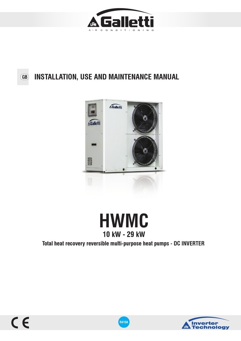
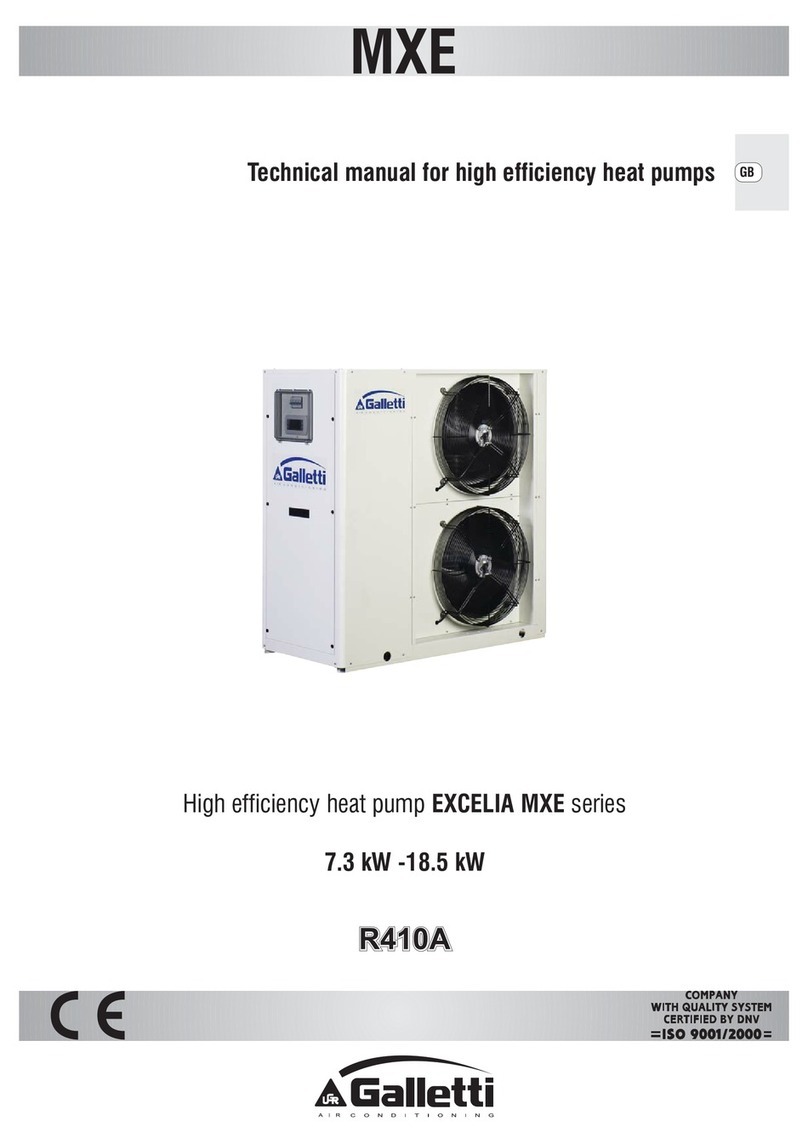
Galletti MPE Service manual

INSTALLATION,USEANDMAINTENANCEMANUAL
MPE
EN
PLUS
» Completely congurable
» Dual-compressor version that guarantees high ecien-
cy at partial loads
» Production of chilled water up to an air temperature of
47 °C
» Incorporable hydraulic kit
4 kW - 76 kW
Chillers and heat pumps
Axial fan Scroll compressor Refrigerant
R-410A
Cooling only Heating/Cooling Packaged
execution
Rotary
compressor
RG66019585-04 06/22

Dear Customer,
Thank you for placing your trust in one of the products of Galletti S.p.a
This product is the result of our work and our commitment to design, research, and production and has been
made from the nest materials, employing state-of-the-art components and production technology.
The CE marking of the product ensures its compliance with the safety requirements of the following directives:
the Machinery Directive, the Electromagnetic Compatibility Directive, the Electrical Safety Directive, and the
Pressure Equipment Directive. Fulllment of the Ecodesign requirements is fully in keeping with the environ-
mental awareness that has always guided our company.
The company certication of the Quality and Safety management system ensures that product quality is
constantly checked and improved, and that the product is manufactured in full compliance with the highest
standards.
By choosing our product, you have opted for Quality, Reliability, Safety, and Sustainability.
At your disposal, once again.
Galletti S.p.a
TRANSLATION BY ORIGINAL INSTRUCTIONS
The water chillers and heat pumps comply with directive 2014/68//EC (PED).
The technical and dimensional data reported in this manual may be modied in view of any product improvement.

Galletti S.p.A. - Via L.Romagnoli 12/a
40010 Bentivoglio (BO) Italy
Made in Italy
CATEGORY 1
Serial number
Code
Date of production
Cooling capacity (W)
Heating capacity (W)
Power supply
Power input (kW)
Weight (kg)
Max power input (kW)
Max running amperage (A)
HP power input (kW)
Refrigerant
Max refrigerant pressure
Max refrigerant temperature (°C)
SAFETY SYMBOLS
Carefully read this manual.
Warning
Use personal protective equipment
Warning:
Electrical and electronic products may not be mixed with
unsorted household waste. Do NOT try to dismantle the
system yourself: the dismant¬ling of the system, treat-
ment of the refrigerant, of oil and of other parts must be
done by an authorized installer and must comply with ap-
plicable legislation. Units must be tre¬ated at a specialized
treatment facility for reuse,recycling and recovery. By en-
suring this product is disposed of correctly, you will help
to prevent potential negative consequences for the envi-
ronment and human health. For more information, contact
your installer or local authority.
USE SUITABLE PPE GLOVES FOR REFRIGERANT, PROTECTIVE
GOGGLES
The unit data are reported on the rating label in this page.
THE LABEL SHOWS THE FOLLOWING DATA:
Ū Series and size of the unit
Ū Date of manufacture
Ū Main technical data
Ū Manufacturer
Ū The label is applied on the unit, usually on the enclos-
ing panels
IMPORTANT: NEVER REMOVE THE LABEL
Ū Unit serial number
Ū The serial number permits to identify the technical
characteristics and the components installed
Ū Without this datum it will be impossible to identify the
unit correctly
GENERAL CAUTIONARY NOTES
Ū Keep this manual intact in a safe place for the all life of
the unit.
Ū Carefully read all the information contained in this
manual, paying special attention to sections marked
"Important" and "Warning"; failure to comply with the
instructions provided could result in injury to persons
or damage to the equipment.
Ū Should a fault occur, consult this manual and if neces-
sary contact the nearest Galletti S.p.A. service centre.
Ū All installation and maintenance operations must be
carried out by qualied personnel, unless otherwise
indicated in this manual.
Ū The rst start up must be carried out exclusively by
qualied personnel and authorized by Galletti S.p.A.
(see warranty sheet attached).
Ū Before performing any work on the unit, disconnect it
from the power supply.
Ū Failure to comply with the rules provided in this man-
ual will result in the immediate invalidation of the war-
ranty.
Ū Galletti S.p.A. shall not accept any liability for injury
or damage resultingcfrom improper use of the equip-
ment or failure to comply with the directions provided
in this manual and on the unit it self.
Ū It's mandatory to install lters heat exchangers protec-
tion will immediately invalidate the warranty.

TABLE OF CONTENTS
1 THE MPE SERIES . . . . . . . . . . . . . . . . . . . . . . . . . . . . p.5
1.1 FIELD OF APPLICATION . . . . . . . . . . . . . . . . . . . . . . . p.5
1.2 MAIN FEATURES . . . . . . . . . . . . . . . . . . . . . . . . . . . . . . p.5
1.3 MODELS AND VERSIONS . . . . . . . . . . . . . . . . . . . . . . p.6
2 CONSTRUCTIVE FEATURES . . . . . . . . . . . . . . . . p.7
2.1 STRUCTURE. . . . . . . . . . . . . . . . . . . . . . . . . . . . . . . . . . . p.7
2.2 CUSTOMISED HYDRAULIC KIT . . . . . . . . . . . . . . . . . p.7
2.3 COOLING CIRCUIT . . . . . . . . . . . . . . . . . . . . . . . . . . . . p.7
2.4 FINNED BLOCK HEAT EXCHANGER . . . . . . . . . . . . p.7
2.5 ELECTRONIC MICROPROCESSOR CONTROL . . . p.7
2.6 ELECTRIC CONTROL BOARD . . . . . . . . . . . . . . . . . . p.7
2.7 OPTIONS . . . . . . . . . . . . . . . . . . . . . . . . . . . . . . . . . . . . . p.7
2.8 FAN DRIVE ASSEMBLY . . . . . . . . . . . . . . . . . . . . . . . . . p.8
3 INSPECTION, CONVEYANCE
DIMENSIONAL AND SITING. . . . . . . . . . . . . . . . p.9
3.1 INSPECTION . . . . . . . . . . . . . . . . . . . . . . . . . . . . . . . . . . p.9
3.2 CONVEYANCE. . . . . . . . . . . . . . . . . . . . . . . . . . . . . . . . . p.9
3.3 SITING AND DAMPERS . . . . . . . . . . . . . . . . . . . . . . . . p.9
3.4 INSTALLATION CLEARANCE REQUIREMENTS
. . . . . . . . . . . . . . . . . . . . . . . . . . . . . . . . . . . . . . . . . . . . . . p.10
3.5 DIMENSIONS . . . . . . . . . . . . . . . . . . . . . . . . . . . . . . . . p.14
4 TECHNICAL FEATURES . . . . . . . . . . . . . . . . . . . . p.21
4.1 MPE C WATER CHILLERS RATED TECHNICAL
DATA . . . . . . . . . . . . . . . . . . . . . . . . . . . . . . . . . . . . . . . . p.21
4.2 MPE H HEAT PUMPS RATED TECHNICAL DATA
. . . . . . . . . . . . . . . . . . . . . . . . . . . . . . . . . . . . . . . . . . . . . . p.22
5 MICROPROCESSOR CONTROL. . . . . . . . . . . . p.26
5.1 USER INTERFACE . . . . . . . . . . . . . . . . . . . . . . . . . . . . . p.26
5.1.1 Display . . . . . . . . . . . . . . . . . . . . . . . . . . . . . . . . . . . . . . . . p.26
5.1.2 Display icon . . . . . . . . . . . . . . . . . . . . . . . . . . . . . . . . . . . . p.26
5.2 KEYS FUNCTIONS . . . . . . . . . . . . . . . . . . . . . . . . . . . . p.27
5.2.1 Keys combined functions . . . . . . . . . . . . . . . . . . . . . . . . . . p.27
5.3 PROGRAMMING BY KEY . . . . . . . . . . . . . . . . . . . . . . p.27
5.3.1 How to access the “Pr1” (user level) . . . . . . . . . . . . . . . . . . p.27
5.3.2 How to access the “Pr2” parameters (Factory level). . . . . . . p.27
5.4 HOW TO CHANGING A PARAMETER VALUE . . . p.27
5.5 SWITCHING ON THE UNIT IN CHILLER HEAT
PUMP MODE. . . . . . . . . . . . . . . . . . . . . . . . . . . . . . . . . p.27
5.6 HOW TO SET THE UNIT STANDBY . . . . . . . . . . . . p.28
5.7 THE FUNCTION MENU KEY MENU. . . . . . . . . . . p.28
5.7.1 Access to Function menu . . . . . . . . . . . . . . . . . . . . . . . . . . p.28
5.7.2 Exit from Function Menu . . . . . . . . . . . . . . . . . . . . . . . . . . p.28
5.7.3 How to display the alarms . . . . . . . . . . . . . . . . . . . . . . . . . p.28
5.7.4 How to reset alarm . . . . . . . . . . . . . . . . . . . . . . . . . . . . . . . p.28
5.8 OTHER FUNCTIONS AVAILABLE BY KEY:. . . . . . . p.28
5.8.1 How to display set point. . . . . . . . . . . . . . . . . . . . . . . . . . . p.28
5.8.2 How to modify the set point. . . . . . . . . . . . . . . . . . . . . . . . p.28
5.9 NO POWER OUTPUT . . . . . . . . . . . . . . . . . . . . . . . . . p.28
5.10 PARAMETERS AND ALARMS LIST . . . . . . . . . . . . . p.28
6 START-UP . . . . . . . . . . . . . . . . . . . . . . . . . . . . . . . . . . p.29
6.1 PRELIMINARY CHECKS . . . . . . . . . . . . . . . . . . . . . . . p.29
7 PLUMBING AND ELECTRICAL
CONNECTIONS . . . . . . . . . . . . . . . . . . . . . . . . . . . . p.30
7.1 PLUMBING CONNECTION . . . . . . . . . . . . . . . . . . . . p.30
7.1.1 General guidelines for plumbing connections . . . . . . . . . . p.30
7.1.2 Recommended water circuit. . . . . . . . . . . . . . . . . . . . . . . . p.30
7.1.3 Filling the system . . . . . . . . . . . . . . . . . . . . . . . . . . . . . . . . p.31
7.2 ELECTRICAL CONNECTIONS . . . . . . . . . . . . . . . . . p.32
7.3 ELECTRICAL DATA . . . . . . . . . . . . . . . . . . . . . . . . . . . p.33
7.4 WATER CIRCUIT . . . . . . . . . . . . . . . . . . . . . . . . . . . . . . p.36
8 OPERATING LIMITS. . . . . . . . . . . . . . . . . . . . . . . . p.38
8.1 OPERATING LIMITS IN CHILLER MODE . . . . . . . . p.38
8.2 OPERATING LIMITS IN HEAT PUMP MODE . . . . p.39
8.3 THERMAL CARRYING FLUID . . . . . . . . . . . . . . . . . . p.39
9 CONTROL AND SAFETY DEVICES . . . . . . . . p.40
9.1 CONTROL DEVICES . . . . . . . . . . . . . . . . . . . . . . . . . . p.40
9.1.1 Service thermostat . . . . . . . . . . . . . . . . . . . . . . . . . . . . . . . p.40
9.1.2 Control device settings. . . . . . . . . . . . . . . . . . . . . . . . . . . . p.40
9.2 SAFETY DEVICES . . . . . . . . . . . . . . . . . . . . . . . . . . . . . p.40
9.2.1 High pressure switch . . . . . . . . . . . . . . . . . . . . . . . . . . . . . p.40
9.2.2 Low pressure switch . . . . . . . . . . . . . . . . . . . . . . . . . . . . . . p.40
9.2.3 Anti-recycle timer. . . . . . . . . . . . . . . . . . . . . . . . . . . . . . . . p.40
9.2.4 Antifreeze thermostat. . . . . . . . . . . . . . . . . . . . . . . . . . . . . p.40
9.2.5 Water differential pressure switch . . . . . . . . . . . . . . . . . . . p.40
9.2.6 Water safety valve. . . . . . . . . . . . . . . . . . . . . . . . . . . . . . . . p.40
9.2.7 Safety device settings. . . . . . . . . . . . . . . . . . . . . . . . . . . . . p.40
10 ROUTINE MAINTENANCE AND CHECKS
. . . . . . . . . . . . . . . . . . . . . . . . . . . . . . . . . . . . . . . . . . . . . . p.41
10.1 CHECKS TO BE PERFORMED BY THE USER . . . . p.41
10.2 CHECKS AND MAINTENANCE TO BE
PERFORMED BY SPECIALISED PERSONNEL. . . . p.41
11 COMPONENTS DESCRIPTION . . . . . . . . . . . . p.42
12 COOLING CIRCUITS . . . . . . . . . . . . . . . . . . . . . . . p.49
13 TROUBLESHOOTING . . . . . . . . . . . . . . . . . . . . . . p.62
14 RETIRING THE UNIT . . . . . . . . . . . . . . . . . . . . . . . p.64

RG66019585-04
All copying, even partial, of this manual is strictly forbidden 5
1 THE MPE SERIES
1.1 FIELD OF APPLICATION
MPE air-condensed water chillers and heat pumps have been
designed to cool and heat water for air conditioning and heating
systems in residential or commercial buildings.
The MPE range units are intended for outdoor installation
(IP24 protection degree), in a position not accessible to the
public.
If protection grids are not provided (accessory) and if the ma-
chine can be reached by non-specialised personnel, access to
the nned coil must be prohibited using appropriate barriers.
Do not install the unit in environments with gas or amma-
ble dusts.
1.2 MAIN FEATURES
MPE water chillers and heat pumps are designed for outdoor
installation in both residential and industrial applications. The
range uses R410A refrigerant, which assures high levels of per-
formance with relatively low energy consumption and features
10 models in the chiller version and 29 models in the heat pump
version, with cooling capacities ranging from 9 to 76 kW and
heating capacities from 5 to 85 kW.
The nned block heat exchangers have been optimised for
R410A and use 8 mm copper pipes, which permit a better heat
exchange and quiet operation of the fans. Their generous sizing
guarantees the production of chilled water even with outdoor
air temperatures as high as 47°C.
In the MPET models, with a double compressor on the same
cooling circuit, the working temperature range is extended fur-
ther and eciency at partial loads increases.
In demanding working conditions the microprocessor controller
activates the capacity control mode, doubling the condensing
surface available to the single compressor.
The self-adaptive logic allows the setpoint to be adjusted au-
tomatically according to the outdoor temperature in order to
reduce consumption and broaden the working temperature
range.
The unit can also function in systems with a low water content,
even without the use of a storage reservoir, thanks to the auto-
matic adjustment which limits the number of compressor starts
and thus extends the life of the compressors themselves.
The exclusive Smart Defrost System (optional feature available
with the advanced controller) can correctly identify an impair-
ment of performance in the outdoor exchanger due to the for-
mation of ice and minimise the process time in relation to nor-
mal operation of the unit.

MPE
INSTALLATION, USE AND MAINTENANCE MANUAL6
1.3 MODELS AND VERSIONS
The MPE series consists of 11 models only cooling mode and
28 models in heat pumps with dierent powers. All models
operates with R410A refrigerant.
NOTE: The choice of some options can make the choice of some
others forbidden or make some selection (elds) mandatory.
Please contact Galletti S.p.A. for verication.
» Conguration options
1 Expansion valve
0 Mechanical
A Electronic
2 Water pump and accessories
1 LP pump + expansion vessel
2 LP run and standby double pump + expansion vessel (advanced controller required)
3 Water buer tank
0 Absent
S Selected
4 Partial heat recovery
0 Absent
D Desuperheater with pump activation contact
5 Air ow modulation
C Condensation control by phase-cut fans
E Condensation control performed by EC fans
6 Antifreezing kit
0 Absent
E Evaporator (tandem unit advanced controller required)
P Evaporator and pump (tandem unit advanced controller required)
S Evaporator, water pump and water buer tank (tandem unit advanced controller required)
7 Acoustic insulation and attenuation
0 Absent
1 Compressor compartment acoustic insulation
2 Compressor sound blanket
3 Compressor compartment acoustic insulation and sound blanket
8 Refrigerant pipework accessories
0 Absent
M Refrigerant pressure gauges
9 Remote control / Serial communication
0 Absent
2 RS485 serial board (Carel / Modbus protocol)
B BACNET IP / PCOWEB serial board (advanced controller required)
F BACNET MS/TP / PCONET board (advanced control required)
G BACNET IP / PCOWEB serial board + supervision software Gweb (advanced controller required)
L LON FTT10 serial board (advanced controller required)
S Remote simplied user panel
X Remote user panel for advanced controller
10 Special coils / Protective treatments
0 Standard
B Pre-painted ns with epoxy painting
C Cataphoresis
I Hydrophilic
R Copper-copper
11 Outdoor nned coil heat exchanger protection
0 Absent
G Outdoor nned coil heat exchanger protection grille
12 Compressors options
0 Absent
1 Power factor capacitors
2 Soft starter
3 Power factor capacitors + soft starter
4 Crankcase compressor heater (CHILLER), outdoor coil trace heater (HP)
13 Onboard controller
1 Basic
2 Advanced
4 Advanced + clock card
Chiller accessories
1701546 Remote simplied user panel
RYKAMF Spring anti vibration shock mounts
RYMCL MyChiller Plus (RS485 serial board and advanced controller required)
RYMCM MyChiller Base (RS485 serial board and advanced controller required)
RYPAM Rubber anti vibration shock mounts
RYRT40 Tank module connection kit
RYT40 Inertial tank module for under-base installation

RG66019585-04
All copying, even partial, of this manual is strictly forbidden 7
2 CONSTRUCTIVE FEATURES
STRUCTURE
Galvanised sheet steel structure treated with a polyester powder
coating (RAL9002) suitable for outdoor applications, for an at-
tractive look and eective resistance to corrosive agents.
Fastening devices are made of non-oxidizable materials, or car-
bon steel that has undergone surface-passivating treatments.
The compressor compartment is completely sealed and may be
accessed on 3 sides thanks to easy-to-remove panels that greatly
simplify maintenance and/or inspection.
On request acoustic insulation can reduce the unit noise
emissions
CUSTOMISED HYDRAULIC KIT
Ū High head pump made entirely of stainless steel, already
congured for use with mixtures of water and ethylene gly-
col up to 25% and providedwith internal thermal protection.
Ū Expansion tank.
Ū Safety valve.
Ū Filling cock (included).
Ū Automatic vent valve.
Ū Water dierential pressure switch and outlet water tempera-
ture probe with anti-freeze thermostat function.
Ū Mechanical Y lter supplied as a standard feature on all mod-
els to protect the evaporator (included).
COOLING CIRCUIT
Ū Scroll type compressors in a tandem conguration that can
be sound insulated (Frame 3 e 4). The adopted components’
eciency, reliability, and noise emission levels represent the
state of the art for scroll compressors.
Ū Brazed plate heat exchangers made of stainless steel and op-
timised for use with R410A.
Ū Finned block condenser with 8 mm copper piping and alu-
minium ns, characterised by ample heat exchange surfaces.
Ū Dehydrating lter.
Ū Flow indicator with humidity indicator.
Ū Thermostatic valve with external equalisation and integrat-
ed MOP function.
Ū Cycle reversing valve (only MPE H)
Ū Check valve (MPE H)
Ū Liquid receiver (MPE H)
Ū High and low pressure switch
Ū Water safety valve
Ū Schrader valves for checks and/or maintenance
Ū Refrigerant pressure gauges (optional)
FINNED BLOCK HEAT EXCHANGER
Made of 8 mm diameter copper pipes and aluminium ns, gen-
erously sized.
The special engineering of the heat exchangers allows defrost
cycles to be carried out at maximum speed in the models with
heat pump operation, which brings clear benets in terms of the
integrated eciency of the whole cycle.
ELECTRONIC MICROPROCESSOR CONTROL
The electronic control enables the complete control of the MPE
unit. It can be easily accessed through a polycarbonate ap with
IP65 protection rating.
The basic controller comes complete with the MODBUS.
Main functions:
Ū Control over the temperature of water entering the evapo-
rator.
Ū Complete alarm management.
Ū Dynamic control of the setpoint according to the outdoor
air temperature.
Ū Can be connected to an RS485 serial line for supervisory /
teleassistance operation
Devices controlled
Ū Compressor
Ū Fans
Ū Water circulation pump
Ū Antifreeze heating element (optional)
Ū Alarm signalling relay
ELECTRIC CONTROL BOARD
The electric control board is constructed and wired in accord-
ance with EEC Directive 73/23, Directive 89/336 on electromag-
netic compatibility and related standards. Made of steel sheet, it
is also protected by the enclosing panels of the machine.
OPTIONS
Ū Incorporable hydraulic kit
Ū Condensation control
Ū Low noise execution
Ū Refrigerant pressure gauges
Ū Antifreeze heating elements on the water circuit
Ū Electronic thermostatic valve

MPE
INSTALLATION, USE AND MAINTENANCE MANUAL8
Ū Heat recovery 25% (chiller)
Ū Special exchangers (hydrophilic treatment, copper-copper,
cataphoresis, anti-corrosion)
2.8 FAN DRIVE ASSEMBLY
Electric fan with 6/8-pole external rotor motor directly keyed to
the axial fan, with internal thermal protection on the windings,
complete with safety grille and dedicated supporting structure.
The fan is housed in a special compartment having a prole de-
signed to optimise ventilation.
The use of nned block heat exchangers with 8 mm diameter
pipes reduces pressure drops on the air side, thus signicantly
improving the noise levels of the units.
The condensation control system continuously and automatical-
ly regulates the fan speed, further limiting the noise emissions
of the unit during nighttime operation and under partial load
conditions.

RG66019585-04
All copying, even partial, of this manual is strictly forbidden 9
3 INSPECTION, CONVEYANCE DIMENSIONAL AND SITING
3.1 INSPECTION
On receiving the unit, check that the packing is intact: the ma-
chine left the factory in perfect conditions and after thorough
inspection.
Should you detect any signs of damage, immediately report
them to the carrier and note them on the delivery slip.
Galletti S.p.A. Must be notied of the entity of the damage with-
in 8 days of the delivery date.
Check that the following items are present:
Ū starting up module,
Ū wiring diagram
Ū warranty certicate
Ū make sure that this manual is intact (68 pagine).
3.2 CONVEYANCE
During handling it is compulsory to check dimensions, weights,
centre of gravity and anchorages. Check as well that lifting and
positioning devices conform to the current safety regulations.
The unit leaves the factory screwed onto a wooden pallet, which
allows it to be easily conveyed with a forklift truck. After remov-
ing the unit from the pallet, handle it gently, without applying
excessive pressure on the side panels, nned coil and fan grille.
You should collect and separate the packing materials (wood,
cardboard, nylon etc.) and make them available for recycling
in order to minimise their environmental impact. Before lifting,
remove the screws fastening the base of the unit to the wood
platform.
The unit must be lifted using Ø 1”steel pipes at least 5mm thick,
to be inserted in the round holes on the base side members (see
gure) and identied by means of stickers. Piping must protrude
of at least 250-300 mm from each side, be slung with ropes of
equal length and secured to the lifting hook (provide stops at
the ends of the pipes to prevent the ropes from slipping o due
to the weight).
Use ropes and belts suciently long to extend beyond the
height of the machine and place spacer bars and boards on the
top to prevent damaging the sides and the top of the unit.
In this phase, before the denitive position, vibration damping
supports can be installed (optional).
AWARNING In all lifting operations make sure that the unit
is securely anchored in order to prevent accidental falls or
overturning.
Use all available lifting points.
» Lifting points
3.3 SITING AND DAMPERS
It is important to bear in mind the following aspects when
choosing the best site for installing the unit:
Ū Size and origin of water pipes;
Ū Location of the power supply;
Ū Solidity of the supporting surface;
Ū Avoid obstacles to the outow of air from the fan which could
cause back suction (see section on 3.5Dimensionsp.14);
Ū Direction of prevalent winds: (position the unit so as to pre-
vent prevalent winds from interfering with the fan air ow).
Prevalent winds opposing the fan air ow will result in a
maximum air temperature below the value indicated in the
operating limits;
Ū Avoid the possible reverberation of sound waves; do not in-
stall the unit in narrow or cramped spaces;
Ū Ensure adequate accessibility for maintenance or repairs
(see section on 3.5Dimensionsp.14).
This appliance is not intended to be used by children or per-
sons with physical, sensorial or mental problems, inexpert
or unprepared, without supervision. Be careful that children
do not approach the appliance.
» Vibration dumpers

MPE
INSTALLATION, USE AND MAINTENANCE MANUAL10
MPE DAMPERS
04 - 08 4
09 - 15 4
18 - 27 -T18 - T25 4
28 - 66 6
T30 -T45 6
T54 -T76 6
3.4 INSTALLATION CLEARANCE
REQUIREMENTS
To guarantee the proper functioning of the unit and access for
maintenance purposes, it is necessary to comply with the mini-
mum installation clearance requirements shown in gures Spazi
installazione MPE H 04 - 08 , spazi installazione MPE 09-15 , spazi
installazione MPE H 18-27; MPE C T18-T25 , spazi installazione
MPE 28-40 - T30 - T42 and spazi installazione MPE T54 - T76 .
Ū Verify that there are no obstacoles in front of the fans air out-
let.
Ū Avoid any and all situations of backow of hot air between
air outlet and inlet of the unit.
Ū If even only one of the above conditions is not fullled,
please contact the manufacturer to check for feasibility.
Ū In the design of the MPE series, special care has been taken
to minimise noise and vibrations transmitted to the ground.
Ū Even greater insulation may be obtained, however, by using
vibration damping base supports (available as optional ac-
cessories).
Ū If vibration damping base supports are adopted, it is strong-
ly recommended also to use vibration damping couplings
on the water pipes.
Ū Whenever the unit is to be sited on unstable ground (various
types of soil, gardens, etc.) it is a good idea to provide a sup-
porting base of adequate dimensions.
AWARNING Heat pump units produce condensation while
operating in the heating mode.

RG66019585-04
All copying, even partial, of this manual is strictly forbidden 11
» MPE H 04 - 08

MPE
INSTALLATION, USE AND MAINTENANCE MANUAL12
» MPE 09 - 15
» MPE T18-T25

RG66019585-04
All copying, even partial, of this manual is strictly forbidden 13
» MPE 28 - 40 - T30 - T42
» MPE T54 - T76

MPE
INSTALLATION, USE AND MAINTENANCE MANUAL14
3.5 DIMENSIONS
» MPE H 04 - 08
LEGEND
1 Water inlet 1" famale
2 Water outlet 1" female
3 Safety valve discharge outlet provided with rubber ring holder
4 Water supply 1/2" famale (optional tap)
5 Water drainage 1/2" female
6 Power supply ø 28 mm
7 Electric control board
8 Vibration dumpers

RG66019585-04
All copying, even partial, of this manual is strictly forbidden 15
» MPE 09 -15
LEGEND
1 Water inlet 1" famale
2 Water outlet 1" female
3 Safety valve discharge outlet provided with rubber ring holder
4 Water supply 1/2" famale (optional tap)
5 Water drainage 1/2" female
6 Power supply ø 28 mm
7 Electric control board
8 Vibration dumpers

MPE
INSTALLATION, USE AND MAINTENANCE MANUAL16
» MPE 18 - 27
LEGEND
1 Water inlet 1" 1/4 famale
2 Water outlet 1" 1/4 female
3 Safety valve discharge outlet provided with rubber ring holder
4 Water supply ½" male (optional tap)
5 Water drainage 1/2" female
6 Power supply ø 28 mm
7 Electric control board
8 Vibration dumpers

RG66019585-04
All copying, even partial, of this manual is strictly forbidden 17
» MPE C T18-T23-T25
LEGEND
1 Water inlet 1" 1/4 female
2 Water outlet 1" 1/4 female
3 Safety valve discharge outlet provided with rubber ring holder
4 Water supply ½" male (optional tap)
5 Water drainage 1/2" female
6 Power supply ø 28 mm
7 Lifting points
8 Vibration dumpers
9 Electric control board
10 User interface

MPE
INSTALLATION, USE AND MAINTENANCE MANUAL18
» MPE 28 - 40 ; MPE T30 - T42
LEGEND
1 Water inlet 1" 1/4 famale
2 Water outlet 1" 1/4 female
3 Safety valve discharge outlet provided with rubber ring holder
4 Water supply ½" male (optional tap)
5 Water drainage 1/2" female
6 Power supply ø 37 mm
7 Electric control board
8 Vibration dumpers

RG66019585-04
All copying, even partial, of this manual is strictly forbidden 19
» MPE H 54 - 66
LEGEND
1 Water inlet 2" female
2 Water outlet 2" female
3 Safety valve discharge outlet provided with rubber ring holder
4 Water supply ½" male
5 Water drainage 1/2" female
6 Power supply
7 Electric control board
8 Fastening points for vibration dampers (accessory)

MPE
INSTALLATION, USE AND MAINTENANCE MANUAL20
» MPE T54 - T76
LEGEND
1 Water inlet 2" famale
2 Water outlet 2" female
3 Safety valve discharge outlet provided with rubber ring holder
4 Water supply ½" male
5 Water drainage 1/2" female
6 Vibration dumpers
Table of contents
Other Galletti Heat Pump manuals
Popular Heat Pump manuals by other brands

Gree
Gree 13-05020 owner's manual

Shott
Shott BP-35WS-B installation manual

Wolf
Wolf BWL-1S-05 Installation and operating instructions

Viessmann
Viessmann VITOCAL 060-A Installation and service instructions

Lampoassa
Lampoassa T 10-15 user manual

Carrier
Carrier XCT7 40VD005-024L-7E-QEE Installation and owner's manual

State Water Heaters
State Water Heaters 100 SERIES User's information manual

Trane
Trane Horizon OABE/F Series Installation, operation and maintenance

Carrier
Carrier Elegant 53QFJ36 owner's manual

Daikin
Daikin ETVZ16S18DA6V Operation manual

Unitary products group
Unitary products group FF-10 installation manual

Daikin
Daikin Altherma 3 H HT EPRA18DAW1 Installer's reference guide