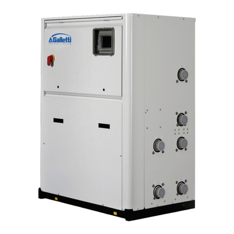
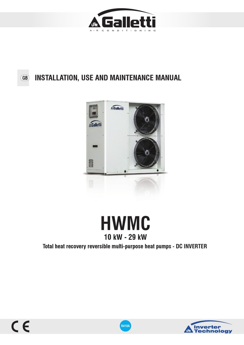
Galletti HiWarm Series User manual

R410A
eco
12 kW - 22 kW - 33 kW
MULTIFUNCTION UNIT: AIR-WATER HEAT PUMP
INSTALLATION, USE AND MAINTENANCE MANUAL
GB


3
All copying, even partial, of this manual is strictly forbiddenRG66007967 - Rev 02
MULTIFUNCTION UNIT: AIR-WATER HEAT PUMP
HiWarm
WARNING READ THIS MANUAL CAREFULLY BEFORE USING THE UNIT.
WARNING Declaration of conformity
The declaration of conformity is attached separately to the documents on board the unit, usually
placed inside the circuit compartment.
Dear Customer,
Whilst thanking you for having chosen a product of ours, we are pleased to provide this manual for
optimal use of our product for maximum comfort.
Please carefully read the recommendations provided in the following pages and place the manual at
the disposal of the unit managers and maintenance technicians.
Our company is at your disposal for any questions you may have both during the unit start-up phase or
any other time.
Our Technical Department is at your disposal for any assistance and spare parts you may require,
especially during routine or special maintenance.
Please nd our contact details below for a more rapid service:
Galletti S.p.A.
Via L.Romagnoli 12/a
40010 Bentivoglio (BO) ITALY
Tel + 39 051 8908111
Fax + 39 051 8908122/3

HIWARM
4All copying, even partial, of this manual is strictly forbidden RG66007967 - Rev 02

5
All copying, even partial, of this manual is strictly forbiddenRG66007967 - Rev 02
1 YOUR INSTALLATION
All the tips required for a perfect installation of the equipment are found in the installation manual.
It is important to place a net lter at both water circuit inlets, which must be made of stainless steel
with a mesh that does not exceed 1 mm.
2 YOUR CONNECTION
All connections must be made correctly. The COMMISSIONING REQUEST FORM lists all that must be
checked before requesting unit start-up.
3 YOUR REQUEST
Send the request form found in the unit documentation by fax, at least one week in advance. Should
this form not be found, please contact GALLETTI:
Tel. (+39) 051 8908111 - Fax (+39) 051 8908122 - e-mail: assistenza@galletti.it
4 OUR APPOINTMENT
Galletti will organise this by asking the Authorised Technical Service Centre in your area to contact
you.
5 OUR
TEST
All the preliminary checks and unit test will be performed together with your personnel.
Your personnel will be provided with instructions for correct unit management.
6 OUR GUARANTEE
The AuthorisedTechnical Service Centre will issue a test certicate once the test is performed, which
represents the warranty of the unit.
Galletti S.p.A. provides you with a customised maintenance program.
START-UP INSTRUCTIONS

HIWARM
6All copying, even partial, of this manual is strictly forbidden RG66007967 - Rev 02
CONTENTS
1 - GENERAL DESCRIPTION 8
1.1 PRECAUTIONS FOR USE 8
1.2 PREMISE 8
1.3 LIABILITY 9
1.4 INTENDED USE 9
1.5 UNIT IDENTIFICATION 10
1.6 GENERAL INSTRUCTIONS 11
2 - SAFETY REQUIREMENTS 12
2.1 GENERAL SAFETY STANDARDS 12
2.1.1 Be familiar with the unit 12
2.1.2 Wear protective clothing 12
2.1.3 Use safety equipment 12
2.1.4 Maintenance and inspection warning signs 12
2.2 GENERAL PRECAUTIONS 13
2.2.1 Safety precautions 14
2.2.2 Accident prevention safety 14
2.2.3 Operational safety 14
2.2.4 Residual risk areas 14
2.3 LOCATION OF THE SAFETY LABELS 15
2.3.1 Description of the safety labels 15
2.4 GENERAL SAFETY RULES 17
2.4.1 Attention and maintenance 17
2.4.2 Fire extinguisher and rst aid 17
2.5 MAINTENANCE PRECAUTIONS 18
2.5.1 Tools 18
2.5.2 Personnel 18
2.5.3 Keeping the unit clean 18
2.5.4 Warning signs 18
3 - DESCRIPTION OF THE PRODUCT 19
3.1 THE RANGES 19
3.2 MAIN COMPONENTS OF THE INDOOR UNIT 21
3.3 SYNCHRONOUS MOTORS 26
3.4 MAIN COMPONENTS OF THE OUTDOOR UNIT 27
3.5 RANGE AND OPERATION 28
3.6 PIPING AND LOAD DESIGN CRITERIA 30
3.7 OPERATING LIMITS 31
4 - INSPECTION, TRANSPORT AND POSITIONING 34
4.1 INSPECTION 34
4.2 LIFTING AND TRANSPORT 34
4.3 UNPACKING 34
4.4 POSITIONING AND INSTALLATION 34

7
All copying, even partial, of this manual is strictly forbiddenRG66007967 - Rev 02
CONTENTS
5 - CONNECTIONS 35
5.1 WATER CONNECTIONS 35
5.1.1 General guidelines for the water connections 35
5.1.2 Technical data of the hydraulic pumps 36
5.2 ELECTRICAL CONNECTIONS 38
6 - MANAGEMENT AND CONTROL 40
6.1 GWEB OPERATION 40
6.2 ELECTRICAL LOAD MANAGEMENT FUNCTION 41
6.3 USER INTERFACE 42
6.3.1 Description of the keypad 42
6.3.2 Main screen 43
6.3.3 Selecting the control mode 43
6.3.4 Selecting the set-point 46
6.3.5 Alarms 47
6.3.6 Operating mode 49
7 - MAINTENANCE AND AFTER SALES SERVICE 50
7.1 TROUBLESHOOTING 50
8 - OPTIONAL STORAGE TANKS 52
9 - TECHNICAL DATA 53
10 - DECOMMISSIONING THE UNIT 55
10.1 ENVIRONMENTAL PROTECTION 55
11 - WATER PRESSURE DROPS 55
11.1 EVAPORATOR PRESSURE DROPS 55
11.2 HEAT RECOVERY UNIT PRESSURE DROPS 55
12 - R410A REFRIGERANT SAFETY DATA SHEET 56

HIWARM
8All copying, even partial, of this manual is strictly forbidden RG66007967 - Rev 02
The operating rules in this manual are solely applicable for the following Models:
HiWarm
The instructions manual must be read and used as follows:
- every unit operator and maintenance technician must carefully read the entire manual and comply with that stipulated
therein;
- the employer is obliged to ensure that the operator satises the aptitude requisites for unit operation and has carefully
read the manual;
- read the instructions manual carefully and consider it an integral part of the unit;
- the instructions manual must be readily available to the operating personnel and maintenance technicians;
- keep the manual throughout the life of the unit;
- make sure that any update is included in the text;
- pass on the manual to any other use or subsequent owner of the unit;
- use the manual in such a way so as not to damage any part of the content;
- for not reason whatsoever are parts of the manual to be removed, torn or rewritten;
- keep the manual away from humidity and heat;
- if the manual is lost or partially damaged and therefore the contents can no longer be read entirely, it is advisable to
request a new manual from the manufacturer by communicating the code found on the cover or the serial number of the
unit.
Pay utmost attention to the following symbols and their meaning. Their purpose is to highlight specic information such as:
The operating rules described in this manual are an integral part of the unit supply.
These rules are also intended for the previously trained operator specically to operate this type of unit and contain all the
necessary and important information for operating safety and optimal, proper use of the unit.
Hurried and incomplete training leads to improvisation, which is the cause of many accidents.
The following recommendations must be read carefully before starting work and strictly complied with:
- the operator must always have the instructions manual at his disposal;
- plan each operation carefully;
- before starting work, make sure the safety devices function correctly and you have no doubts on how they work; otherwise,
do not start-up the unit;
- strictly comply with the precautions regarding specic risks referred to in this manual;
- preventive and thorough maintenance guarantees constant enhanced unit operating safety. Never delay repairs and
always have them carried out solely by qualied personnel; only original spare parts are to be used.
1 - GENERAL DESCRIPTION
1.1 PRECAUTIONS FOR USE
1.2 PREMISE
WARNING With reference to additional information or tips for the unit to be used correctly.
ATTENTION With reference to dangerous situations that could arise while using the unit, in order to
prevent damaging objects and the unit itself.
With reference to dangerous situations that could arise while using the unit, in order
guarantee personal safety.
DANGER

9
All copying, even partial, of this manual is strictly forbiddenRG66007967 - Rev 02
The MANUFACTURER cannot be held liable for any personal accident or damage to property, which may derive from:
- failure to comply with the instructions provided in this manual regarding unit management, use and maintenance;
- violent actions or incorrect manoeuvres when performing maintenance on the unit;
- alterations made to the unit without prior written authorisation from the MANUFACTURER;
- incidents beyond the normal and proper use of the unit.
In any case, if the user attributes the incident to a defect in the unit, he must prove that the damage caused was a main and
direct consequence of this“defect”.
HiWarm is a residential air-water heat pump that exchanges heat with the external air and, with no combustion or ame,
warms or cools the home and autonomously produces technical hot water for domestic purposes.
Their use is recommended within the operating limits specied in this manual, otherwise the warranty cover provided for in
the sales contract will be rendered null and void.
Any other use is to be considered inappropriate and the manufacturer declines all liability for any damage caused to persons,
property or the unit that may derive from such use.
1.4 INTENDED USE
1.3 LIABILITY
- When installing or servicing the unit the rules stipulated in this manual must be complied
with together with those on board the unit and in any case take all the precautions
necessary.
- The pressurised uids in the cooling circuit and the presence of electrical components can cause hazardous
situations during installation and maintenance operations.
- Therefore, only qualied personnel may perform any work on the unit.
- THE UNIT MUST ONLY BE COMMISSIONED BY QUALIFIED PERSONNEL, AUTHORISED BY THE COMPANY PLACING IT
ON THE MARKET (SEE ATTACHMENT).
- FAILURE TO COMPLY WITH THE RULES STIPULATED IN THIS MANUAL AND ANY ALTERATION TO THE UNIT WITHOUT
PRIOR AUTHORISATION WILL IMMEDIATELY RENDER THE WARRANTY NULL AND VOID.
- Before performing any work on the unit, make sure it has been disconnected from the power supply.
- Only original spare parts must be used for repairs or maintenance operations. The MANUFACTURER declines all
liability for damage deriving from non-compliance with the above-mentioned points.
- The unit is covered by the warranty according to the contractual agreements for the sale.
- However, the warranty is rendered null and void if the regulations and user instructions stipulated in this manual
are not complied with.
- If a fault should occur, do not try to repair it yourself or have an unauthorised technician perform the repairs. The
warranty will otherwise be rendered null and void.
ATTENTION
- Set in unit in environments where there is no risk of explosion, corrosion or re.
- Improper use could cause serious repercussions on the unit.
- All routine and special maintenance operations must be performed with the unit o and
the power supply disconnected.
- Wait about 30 minutes after switching the unit o before performing any maintenance in order to prevent burns.
DANGER

HIWARM
CЄ 0398
Modello - Model HWM0XXP
Matricola - Serial number HFXXXXXXXXX
Data di produzione - Date of production 20-06-11
Categoria PED/ CE 97/23 Category II
Procedura di valutazione conformità - Conformity module D1
Massima pressione esercizio - Max working pressure [bar-r] 41,5
"Max pressione esercizio lato bassa pressione (carcassa compr.)
Max working pressure low pressure side (compr. shell) [bar-r]" 41,5
Max temp. di stoccaggio - Max storage temperature [°C] 42°C
Max temp. funzionamento - Max ambient working temperature [°C] 42° C
Min.temp.ambiente di funzionamento-Min ambient working temp. [°C] -15°C
Potenza frigorifera nominale - Nominal Cooling Capacity [ kW ] /
Potenza nominale in riscaldamento - Nominal Heating Capacity [ kW ] /
Refrigerante - Refrigerant [Ashrae 15/1992] R410A
Carica refrigerante - Refrigerant charge [kg] (1*)(precharge)
Carica refrigerante denitva - Denitive Refrigerant charge [kg] (2*)
Peso a vuoto - Empty weight [kg] 170
Taratura press. lato ALTA - HIGH pressure Switch Set [bar-r] 41,5
Taratura press. lato BASSA - LOW pressure Switch Set [bar-r] 1,5
"Taratura valvola sicurezza refrigerante
Safety valve refrigerant Set [bar-r]" -
"Taratura valvola sicurezza acqua
Safety valve water side Set [bar-r]" -
Alimentazione - Power supply 230/1/50Hz
Potenza assorbita Nominale - Nominal power input [kW] 5
Corrente nominale - Nominal absorbed current [A] 22
Corrente massima - Full load ampere FLA [A] 22
Corrente di spunto - Starting Current LRA [A] 0,0
Schema elettrico - Wiring diagram HF620AXXXX
Schema frigorifero - Refrigeration diagram HF630AXXXX
CЄ 0398
Modello - Model HWO0XX
Matricola - Serial number HFXXXXXXXXX
Data di produzione - Date of production 20-06-11
Peso a vuoto - Empty weight [kg] 50
Alimentazione - Power supply 230/1/50Hz
Potenza assorbita Massima - Maximum power input [kW] 0,4
Corrente massima - Full load ampere FLA [A] 1,66
Corrente di spunto - Starting Current LRA [A] 0,0
10 All copying, even partial, of this manual is strictly forbidden RG66007967 - Rev 02
- Before performing any work on the unit, each operator must be perfectly aware of how the
unit and its controls work and must have read and understood all the technical information
in this manual.
- It is forbidden to use the unit in conditions or for purposes other than those stipulated in this manual and the
MANUFACTURER cannot be liable for faults, problems or accidents due to non-compliance with this prohibition.
- Do not repair the high pressure pipes with welding.
- It is prohibited to tamper with, alter or modify, even partially, the systems or equipment referred to in the
instructions manual, particularly the guards and symbols regarding personal safety.
- It is also prohibited to operate in any way other than that stipulated or disregard required safety operations.
- Safety guidelines together with general information provided in this manual are particularly important.
ATTENTION
Each unit is distinguished by an identication label on the
frame, which bears all the data required for installation,
maintenance and unit traceability. Take note of the model,
serial number, the denitive refrigerant charge and the
reference drawings of the unit found at the end of this
manual, in order to be easily retrieved if the data label
deteriorates and maintenance is required.
(1*) The indicated refrigerant charge is preloaded inside the unit before leaving
the factory.
(2*) The denitive refrigerant charge must be written by the technician who
installs the unit and once installation is complete.
1.5 UNIT IDENTIFICATION
MANUFACTURER DATA
MANUFACTURER DATA

11
All copying, even partial, of this manual is strictly forbiddenRG66007967 - Rev 02
1.6 GENERAL INSTRUCTIONS
- It must be stored carefully in a place that is known by the user of the unit, managers
and operators in charge of transport, installation, use, maintenance, repairs and nal
dismantling.
- This manual indicates the intended use of the unit and provides instructions regarding transport, installation,
assembly, adjustment and use. It provides information regarding maintenance, ordering spare parts, the presence
of residual risks and personnel training.
- It is important to remember that the use and maintenance manual can never replace adequate user experience.
This manual represents a reminder of the main operations to be performed by operators who have received
specic training, for example by attending training courses held by the manufacturer, with reference to particular
maintenance operations.
- This manual is to be considered an integral part of the unit and must be stored near the unit in a special container
until the unit is demolished. Request a new copy from the manufacturer if it is lost or deteriorated.
- Make sure all the users have understood the user instructions well together with the meaning of any symbols on
the unit.
- Potential accidents can be prevented by following these technical instructions with reference to the Machinery
Directive 2006/42/EC and subsequent amendments.
- In any case, always comply with the national safety regulations.
- Do not remove or damage the safety devices, labels and notices, especially those imposed by law.
- Adhesive labels intended for safer use are applied to the unit, therefore, it is very important to replace them if they
become illegible.
- This manual reects the applicable technology at the time the unit is sold and cannot be considered inadequate
due to subsequent updates based on new experience.
- The MANUFACTURER has the right to update the production and manuals, without being obliged to update
previous production and manuals, except for exceptional cases.
- Please call on the telephone numbers found in this manual for any requests for updates of the use and maintenance
manual or supplements, which are to be considered an integral part of the manual.
- Contact the MANUFACTURER for further information and to submit any proposals on how to improve the manual.
- The MANUFACTURER kindly asks you to report the address of the new owner if the unit is passed on to third
parties, in order to facilitate forwarding any supplements of the manual to the new user.
ATTENTION

HIWARM
12 All copying, even partial, of this manual is strictly forbidden RG66007967 - Rev 02
Every operator must use personal protective equipment
such as gloves, helmet, safety goggles, safety shoes and
noise protection ear mus.
Place a rst aid kit and a re extinguisher near the unit.
The extinguisher must always be fully loaded. Use it
according to the Standards in force.
Apply a "WORKS IN PROGRESS" sign on all sides of the unit.
Carefully check the unit according to the list of operations
specied in this manual.
The unit must only be used by qualied personnel, who is obliged to be aware of the lay-out and function of all the controls,
instruments, indicators, warning lights and various labels.
2 - SAFETY REQUIREMENTS
2.1 GENERAL SAFETY STANDARDS
2.1.1 Be familiar with the unit
2.1.2 Wear protective clothing
2.1.3 Use safety equipment
2.1.4 Maintenance and inspection warning signs
WORKS IN
PROGRESS

13
All copying, even partial, of this manual is strictly forbiddenRG66007967 - Rev 02
The Machinery Directive provides the following denitions:
DANGER ZONE: any zone within and/or around machinery in which a person is subject to a risk to his health or
safety.
EXPOSED PERSON: any person wholly or partially in a danger zone.
OPERATOR: the person or persons installing, operating, adjusting, maintaining, cleaning, repairing or
moving machinery.
2.2 GENERAL PRECAUTIONS
- It is mandatory to read and comply with the instructions provided in this use and
maintenance manual before performing any operation or maintenance on the unit.
It is too late to do so while working: persons may be seriously injured and property seriously damaged if operations
are performed incorrectly or the unit is not used as intended.
- The employer must provide all the operators with the details regarding the risk of accidents, especially those
deriving from noise, the personal protective equipment provided and the general accident prevention regulations
implemented by international laws or regulations or those applicable in the country of use.
All the operators must comply with international accident prevention regulations and those applicable in the
country of use in order to prevent potential accidents.
Please note that the European Union has issued certain Directives regarding health and safety of workers which
every employer is obliged to comply with and enforce.
- Before performing any work on the unit, each operator must be perfectly aware of how the unit and its controls
work and must have read and understood all the information in this manual.
WARNING
- It is strictly prohibited to remove or tamper with any safety device.
- All routine and special maintenance operations together with any installation must be
performed with the unit o and the power supply disconnected.
- Once the unit is cleaned, the operator must make sure there are no worn or damaged parts or others that are not
fastened securely; otherwise, a maintenance technician must be asked to intervene.
Particular attention must be paid to the integrity of the pressurised pipes or other components subject to wear.
Also make sure there are no leaking uids or hazardous substances.
Should there be any leak, the operator is prohibited from restarting the unit before having resolved the problem.
If such problems arise, the operator must ax a sign on the unit before abandoning it, thereby indicating that
maintenance is in progress and it is prohibited from starting it up.
- It is prohibited to use ammable uids to clean the unit.
- Periodically check the state of the labels and if necessary, replace them.
- The operator's workplace must be kept clean, tidy and free from objects that could hinder movements.
- The operators must not perform awkward operations, in uncomfortable positions, that could compromise their
balance.
- The operators must pay attention to risks pertaining to clothing and/or being caught or entangled in moving
parts. It is recommended to use a cap to put up long hair.
- Chains, bracelets and rings can also pose a hazard.
- The workplace must be adequately lit up for the intended operations. Insucient or excessive lighting can pose
risks.
- The instructions, accident prevention regulations and warnings provided in this manual must always be complied
with.
WARNING
It is prohibited to tamper with or replace parts of the unit that are not specically authorised
by the MANUFACTURER.
Using accessories, consumables or spare parts other than those recommended by the MANUFACTURER and/or
stipulated in this manual can constitute a risk for the operators and/or damage the unit.
Any alteration to the unit that is not specically authorised by the MANUFACTURER relieves the manufacturer from
any civil or criminal liability.
ATTENTION

HIWARM
d
a
c
b
a
14 All copying, even partial, of this manual is strictly forbidden RG66007967 - Rev 02
The units have been designed and built according to the current state-of-the-art and technical rules in force regarding
residential air-water heat pumps that exchanges heat with the external air. Applicable laws, provisions, regulations, decrees
and directives to such machinery have been complied with.
The materials used and the parts of equipment, as well as production procedures, quality and control assurance comply with
the highest standards of safety and reliability.
Unit performance, continuous operation and durability are maintained by using the above-mentioned materials and parts
for the purposes specied in this user manual, handling them with due care and performing thorough maintenance and
up-to-standard service.
The MANUFACTURER cannot be held liable for accidents caused when using the unit, due to the user not complying with
laws, provisions, regulations and standards in force regarding uid chillers and heat pumps.
The MANUFACTURER cannot be held liable in case of malfunctions and damage if the unit:
- is used for purposes other than those intended;
- is not handled and maintained according to the operating rules specied in this manual;
- is not serviced regularly and continuously as prescribed or non-original spare parts are used;
- has a component that is either modied or replaced without written authorisation from the MANUFACTURER, especially
when the eciency of the safety systems is intentionally reduced or eliminated;
- is used beyond the ambient temperature limits allowed.
2.2.1 Safety precautions
2.2.2 Accident prevention safety
2.2.3 Operational safety
2.2.4 Residual risk areas
It has not been possible to eliminate certain residual risks during the design phase, found in
some areas of the unit, or protected with guards due to specic features of the unit.
Each operator must be aware of the residual risks on this unit in order to prevent potential
accidents.
DANGER
WARNING In order to prevent the above-
mentioned risks, it is very
important to comply with the
following:
a Use the electric panel in compliance with the
manufacturer's instructions. Do not place metal
objects inside the electric panel. Do not place
ammable substances near the unit.
b Do not alter any component of the cooling circuit and
do not operate the unit beyond the limits stipulated
by the manufacturer.
c Dispose of all the material that compose the unit
correctly and use suitable equipment to collect the
refrigerant gas (see Chap.10).
d Do not touch the internal components without
adequate safety devices during operation.
Residual risk areas:
a Risk of short circuit and re.
b Risk of explosion due to the presence of pressurised
circuits.
c Risk of pollution due to the presence of refrigerant in the
circuit.
d Risk of burns due to the presence of hot surfaces.

a
a b
b
4
1 3
6
4
5
2
15
All copying, even partial, of this manual is strictly forbiddenRG66007967 - Rev 02
a Warning of danger due to the user not being aware of all the functions of
the unit and the consequent risks.
b Read the use and maintenance manual carefully before operating the unit.
Power supply label.
a Do not use water to extinguish re.
b Do not smoke and/or use open ames.
1
2
3
2.3 LOCATION OF THE SAFETY LABELS
2.3.1 Description of the safety labels
ALIMENTAZIONE ELETTRICA
POWER SUPPLY
SPG.VERSORGUNGSTEIL
400V/3/50Hz

HIWARM
a
bc
16 All copying, even partial, of this manual is strictly forbidden RG66007967 - Rev 02
a Electric voltage hazard.
b Risk of shearing in the nned coil area.
c Risk of burns.
Liquid refrigerant.
Hazard: moving mechanical parts.
4
5
6

17
All copying, even partial, of this manual is strictly forbiddenRG66007967 - Rev 02
Many accidents and damage are caused due to maintenance errors, such as:
- no water in the circuit;
- incorrect percentage of refrigerant in the circuit;
- inadequate refrigerant;
- failure to keep the unit area clean;
- circuit ineciency (pipe connections, loose pipes, screws, etc.).
Maintenance must be performed carefully even for personal safety.
Never delay repairs.
Only specialised or authorised personnel must perform repairs.
Always comply with the following safety standards, even when you are completely familiar with all the operating elements:
- Always keep the unit and its surrounding area clean.
- Before starting work check that the safety devices are in perfect working condition.
- Make sure that no unqualied or unauthorised persons enter the unit area.
- Verify that the re extinguisher is in place.
- Periodically verify that the re extinguishers are loaded and all operators know how to use them.
- It is important to know where the rst aid kit is kept.
- Periodically verify that the rst aid kit is equipped with disinfectant, bandages, medicine, etc.
- It is important to know what to do in case of re.
- Make sure the emergency telephone numbers are readily available and nearby.
If a re breaks out, use the re extinguisher according to the relative regulations in force.
Contact the re brigade.
2.4 GENERAL SAFETY STANDARDS
2.4.1 Attention and maintenance
2.4.2 Fire extinguisher and rst aid
WARNING The owner of the property where the unit is installed is responsible for providing the re
extinguisher.

HIWARM
18 All copying, even partial, of this manual is strictly forbidden RG66007967 - Rev 02
Personal injury is prevented by not using worn or damaged, low quality or makeshift tools.
Routine maintenance specied in this manual must only be performed by authorised and trained personnel.
Contact the MANUFACTURER for maintenance or repairs that is not specied in this manual.
Stains of oil and grease and scattered tools or broken parts are hazardous as persons can slip or fall. Always keep the unit
area clean and tidy.
Do not use diesel or petroleum to clean the unit as they leave an oily layer that increases dust adhesion, and neither solvents
must be used (even if weak) as they damage the paint and increase the formation of rust.
If a jet of water penetrates the electrical equipment the contacts oxidise and the unit can malfunction.
Therefore, do not use jets of water or steam on the sensors, connectors or any electrical part.
Switch the unit o before performing any maintenance.
Serious or fatal injury could be caused if other persons
start-up the unit and activate the control buttons while
maintenance is performed.
Warning signs must be placed around the unit before
performing any maintenance in order to prevent such risks.
2.5 MAINTENANCE PRECAUTIONS
2.5.1 Tools
2.5.2 Personnel
2.5.3 Keeping the unit clean
2.5.4 Warning signs
ATTENTION The manufacturer cannot be held liable for damage caused if modied tools are used.
DO NOT START-UP!
MAINTENANCE
IN PROGRESS

19
All copying, even partial, of this manual is strictly forbiddenRG66007967 - Rev 02
3 - DESCRIPTION OF THE PRODUCT
3.1 THE SERIES
HiWarm is a residential air-water multifunction heat
pump that absorbs cold or heat from the external air and
simultaneously, with no combustion or ame, warms or
cools the home and autonomously produces domestic hot
water, prioritised or total heat recovery in cooling mode.
The product is available in three sizes, classied according to
cooling capacity in nominal conditions, i.e. water produced
at 12 / 7°C with the external air at 35°C. The following
features are common in all three:
- Split unit with compressor mounted in the indoor
unit, thereby reducing the external noise emission and
allowing for a light outdoor unit, which can be positioned
at a height with simple brackets.
- Outdoor unit for indoor use, ductable, compact with backward-curved blade fans activated by an EC synchronous
permanent magnets motor, designed for attics.
- Expansion device: EEV (electronic expansion valve) to benet from the possibility of generating thermodynamic cycles
under reduced pressure changes with signicant COP advantages.
- Built-in pump control on system side and DHW side: both pumps are managed directly by the unit.
Three models can be chosen from, classied according to the maximum cooling capacity they can produce:
012 022 033
The dimensions of the indoor unit can be divided in two frame sizes, for each model:
Frame1
- HiWarm012: (LxHxD)= 803x1120x501.5 mm
Frame2
- HiWarm022: (LxHxD)= 803x1247x606 mm
- HiWarm033: (LxHxD)= 803x1247x606 mm
The dimensions of the outdoor units with axial fans are dierent for each model:
Frame1
- HiWarm012: (LxHxD)= 1120x1230x450 mm
Frame2
- HiWarm022: (LxHxD)= 1410x1280x450 mm
- HiWarm033: (LxHxD)= 2000x1512x550 mm

HIWARM
20 All copying, even partial, of this manual is strictly forbidden RG66007967 - Rev 02
Double water circuit:
- Air conditioning circuit with reversible cooling circuit side and variable set-point between min/max with potential-free
contact or with 0-10V or 4-20 mA signal.
- Total heat recovery (for simultaneous cooling) or in any case prioritised DHW circuit. This circuit is separate and does
not need long heating/cooling stages of inertial storage, like similar products on the market, which jeopardise energy
eciency especially during summer operation.
The basic selection when developing the range of multifunction units consists in using the following:
- Scroll or twin-rotary compressors.
- Brazed plates.
- High-eciency fans.
- Electronic expansion valve.
- AISI 316 Stainless steel high-eciency plate heat exchangers.
- Advanced electronic control allows load partialisation requirements to be adequately met.
For optimal partial load operation, which is ever more an object of evaluation and a discriminating factor in the technical
choice of heating technicians.
The structure of the HiWarm units has the following characteristics:
- Indoor unit:
side panelling in galvanised sheet metal painted with polyester epoxy powders and polymerised in the oven at 180°C and
a front cover that incorporates the Display, on two basic levels (LCD) and a 10”Graphic Touch Screen Windows CE. The unit
is fully panelled but can be accessed on 3 sides since the panels can be easily removed, thereby simplifying maintenance
and/or inspections. All routine maintenance is performed from the front of the unit.
- Outdoor unit:
side panelling in galvanised sheet metal painted with polyester powders and polymerised in the oven at 180°C.The unit is
totally faired and panelled and is available in RAL9002 (Grey White).
6-pole axial fans with blades having a high degree of overlapping, combined with asynchronous motors with an external
rotor (or synchronous with permanent magnets) and continuous modulation of the rotation speed.
- Remote unit for indoor installation (attic):
panelling in galvanised sheet metal painted with polyester powders and polymerised in the oven at 180°C. The unit is
totally faired and is available in RAL9002 (Grey White).
Radial fans with brushless motors are used, which are ideal for continuous and ecient modulation. Maximum head
available at 200 Pa.
The components are distributed to guarantee easy access and the layout ensures optimum weight distribution on the unit's
base.
This manual suits for next models
3
Table of contents
Other Galletti Heat Pump manuals
Popular Heat Pump manuals by other brands

Gree
Gree Vireo GEN3 3VIR09HP115V1AH owner's manual

Kensa Heat Pumps
Kensa Heat Pumps Shoebox Installation and commissioning manual

Hayward
Hayward HP50AEE Installation instructions manual

Daikin
Daikin EMRQ8ABY1 installation manual

Johnson Controls
Johnson Controls Frick IDC2 Service manual

Swim & Fun
Swim & Fun PRO 1238 user manual