Galletti KP User manual

UTN
I
GB
F
D
H
NL
P
E
KP INTERFACCIADI POTENZA
KP POWER INTERFACE
KP INTERFACE DE PUISSANCE
KP LEISTUNGSSCHNITTSTELLE
KP INTERFAZ DE POTENCIA
KP INTERFACE DE POTÊNCIA
KP VERMOGENSINTERFACE
KP TELJESÍTMÉNYINTERFÉSZ

KPKP
KPKP
KP
2
FC66000758 - rev. 01
È severamente vietata la riproduzione anche parziale di questo manuale / All copying, even partial, of this manual is strictly forbidden
IGB
I
GB
CARATTERISTICHETECNICHE
Alimentazione: 230 V -15% + 10%..60HZ
Contatti in uscita: 4 x 3 A 250 V
Temperatura di funzionamento: 0°C..+40°C
Limiti di umidità: 20%..80% Ur
non condensante
Grado di protezione: IP30
Contenitore: Tecnopolimero classe VO
DIN mm 105 x 90 x 70
Peso: 265gr.
L'interfaccia di potenza KP viene utilizzata per collegare
parallelamente fino a 4 apparecchi ad un unico comando.
Prevista per il montaggio su guida Din, normalmente alloggiata nei quadri
elettrici, èabbinabile atutteleversioni serie èstroealle unitàtermoventilanti
UTN (solo per i modelli 06 e 08).
INSTALLAZIONE
- Incastrare l'interfaccia di potenza KP alla guida Din.
- Eseguire i collegamenti elettrici in assenza di tensione come indicato
negli schemi delle figure (da 1 a 10) nelle quali è rappresentato:
Figura 1: TD (pannello di comando per installazione a parete) + KP.
Figura 2: TDC (pannello di comando per installazione a parete) + KP.
Figura 3: TD4T (pannello di comando per installazione a parete ad 1
valvola)+ KP.
Figura4: TD4T (pannellodicomandoper installazioneaparetea 2valvole)
+KP.
Figura 5: CDE (commutatore di velocità a parete) + TA (termostato
ambienteelettromeccanico) + KP.
Figura 6: CDE + TA2 (termostato ambiente con selettore stagionale) +
KP.
Figura 7: CD (commutatore di velocità ad incasso a parete) + TA + KP.
Figura 8: CD + TA2 + KP.
Figura 9: MYCOMFORT BASE (comando a parete a microprocessore:
controllo automatico del ventilconvettore, valvola e resistenza elettrica)
+KP.
Figura 10: MYCOMFORT MEDIUM (comando a parete a
microprocessore: controllo automatico del ventilconvettore, valvola e
resistenza elettrica) + KP.
Figura 11: MYCOMFORT LARGE (comando a parete a
microprocessore: controllo automatico del ventilconvettore, valvola e
resistenza elettrica) + KP.
Figura 12: LED503 (comando a parete a microprocessore:
controllo automatico del ventilconvettore, valvola e resistenza elettrica)
+KP.
I collegamenti tratteggiati vanno effettuati dall'installatore.
Per ogni ventilconvettore / unità termoventilante (UTN) nella linea di
alimentazione deve essere presente un sezionatore di rete onnipolare
in categoria di sovratensione III.
N.B. Collegare un solo ventilconvettore (fan-coil) per linea (Max.1/10
HP).
Negli schemi elettrici sono utilizzate le seguenti abbreviazioni:
Le dimensioni di ingombro dell'interfaccia di potenza KP sono riportate in
figura 13.
COMEORDINARE
Interfaccia di potenza KP codice EYKP.
GY Grigio=velocità media (UTN)
IL Interruttore di linea, non fornito
MMotore ventilatore
RD Rosso=velocità minima
WH Bianco=comune
BK Nero=velocità massima
BU Blu=velocità media
Ccommutatore di velocità
CN Connettore a faston
FFusibile di protezione, non fornito
GY Gray=averagespeed(UTN)
IL Lineswitch(notsupplied)
MFanmotor
RD Red = minimum speed
WH White=common
BK Black=maximumspeed
BU Blue=averagespeed
CSpeedselectorswitch
CN Fast-onconnector
FSafetyfuse(notsupplied)
The KP power interface is used for connecting up to 4 units in
parallel to one control.
TobeinstalledonaDINguide,usuallyhousedintheelectricboards,itmay
becoupledtoalltheèstroseriesversionsandtotheUTNairhandlingunits
(only for models 06 and 08).
INSTALLATION
- Fit the KP power interface into place in the DIN guide.
- Make the electrical connections with poser OFF as indicated in the
diagrams of the figures (from 1 to 10) that show the following:
Figure 1: TD (control panel for wall-mounting) + KP.
Figure 2: TDC (control panel for wall-mounting) + KP.
Figure 3: TD4T (control panel for wall-mounting with 1 valve) + KP.
Figure 4: TD4T (control panel for wall-mounting with 2 valves)
+KP.
Figure 5: CDE (wall-mounted speed selector switch)+TA
(electromechanical room thermostat) + KP.
Figure 6: CDE + TA2 (room thermostat with season selector) + KP.
Figure 7: CD (recessed wall-installation speed selector switch) + TA +
KP.
Figure 8: CD + TA2 + KP.
Figure 9: MYCOMFORT BASE (microprocessor-based wall control:
automatic control of the fan-coil unit, valve and heating element) + KP.
Figure 10: MYCOMFORT MEDIUM (microprocessor-based wall
control:automaticcontrolof the fan-coil unit, valve and heating element)
+KP.
Figure 11: MYCOMFORT LARGE (microprocessor-basedwall control:
automatic control of the fan-coil unit, valve and heating element) + KP.
Figure 12: LED503 (microprocessor-based wall control: automatic
control of the fan-coil unit, valve and heating element) + KP.
The hatched connections are to be performed by the installer.
An omnipolar mains isolator in overvoltage category III must be present
for every fan coil / thermal - ventilating unit (UTN) in the power supply
line.
NOTE: Connect only one fan-coil unit per line (Max.1/10 HP).
Thefollowingabbreviationshavebeenusedinthewiringdiagram:
The overall dimensions of the KP power interface are shown in figure
13.
HOWTO PLACEYOUR ORDER
Please indicate:
KP powerinterface code EYKP.
TECHNICALSPECIFICATIONS
Power supply: 230 V -15% + 10%..60HZ
Contacts at output: 4 x 3 A 250 V
Operating temperature: 0°C to +40°C
Humidity limits: 20% to 80% RH
non-condensing
Protection rating: IP30
Container: Thermoplastic substance class VO
DIN mm 105 x 90 x 70
Weight: 265gr.

3FC66000758 - rev. 01
KPKP
KPKP
KP
È severamente vietata la riproduzione anche parziale di questo manuale / All copying, even partial, of this manual is strictly forbidden
DF
GY Gris = vitesse moyenne (UTN)
IL Interrupteurdeligne,nonfourni
MMoteurventilateur
RD Rouge = vitesse minimale
WH Blanc = commun
BK Noir = vitesse maximale
BU Bleu=vitessemoyenne
CCommutateurdevitesse
CN Connecteuràraccordrapide
FFusibledeprotection,nonfourni
GY Grau = mittlere Geschwindigkeit (UTN)
IL Netzschalter,nichtimLieferumfang
MMotorGebläse
RD Rot=Mindestgeschwindigkeit
WH weiß=gemeinsameLeitung
BK Schwarz = Höchstgeschwindigkeit
BU Blau = mittlere Geschwindigkeit
CGeschwindigkeitsumschalter
CN Faston-Stecker
FSicherung, nicht im Lieferumfang
L’interface de puissance KP est utilisée pour connecter
parallèlement jusqu’à 4 appareils à une seule commande.
PrévuepourlemontagesurrailDin,normalementlogéedanslestableaux
électriques, elle peut être associée à toutes les versions série èstro
et aux Unitésde thermoventilationUTN (exclusivement pour lesmodèles
06 et 08).
INSTALLATION.
- Encastrer l’interface de puissance KP dans le rail Din.
- Réaliser les connexions électriques en l’absence de tension comme
indiqué sur les schémas des figures (de 1 à 10) dans lesquelles on
représente :
Figure 1: TD (panneau de commande pour une installation murale) +
KP.
Figure 2: TDC (panneau de commande pour une installation murale)
+KP.
Figure 3: TD4T (panneau de commande pour une installation murale
à 1 soupape) + KP.
Figure 4: TD4T (panneau de commande pour une installation murale
à 2 soupapes)+ KP.
Figure 5: CDE (commutateur de vitesse mural) + TA (thermostat
d’ambiance électro-mécanique) + KP.
Figure 6: CDE + TA2 (thermostat d’ambiance avec sélecteur de
saison) + KP.
Figure 7: CD (commutateur de vitesse à encastrement mural) + TA +
KP.
Figure 8: CD + TA2 + KP.
Figure 9: MYCOMFORT BASE (commande murale àmicroprocesseur
: contrôle automatique du ventilo-convecteur, soupape et résistance
électrique) + KP.
Figure 9: MYCOMFORT MEDIUM (commande murale à
microprocesseur:contrôleautomatiqueduventilo-convecteur,soupape
et résistance électrique) + KP.
Figure9:MYCOMFORTLARGE(commandemuraleàmicroprocesseur
: contrôle automatique du ventilo-convecteur, soupape et résistance
électrique) + KP.
Figure 9: LED503 (commande murale à microprocesseur : contrôle
automatique du ventilo-convecteur, soupape et résistance électrique)
+KP.
Les connexions indiquées par des tirets doivent être effectuées par
l’installateur.
Pour chaque ventilo-convecteur / unité de thermoventilation UTN dans
laligned'alimentation,unsectionneurderéseauomnipolaireencatégorie
de surtension III doit être présent.
N.B. Connecter un seul ventilo-convecteur (fan-coil) par ligne (max.1/
10 HP).
Les abréviations suivantes sont utilisées dans les schémas électriques:
Les dimensions d’encombrement de l’interface de puissance KP sont
reprises sur la figure 13.
COMMANDE.
Interface de puissance KP code EYKP.
Die Leistungsschnittstelle KP wird für den parallelen Anschluß
von bis zu 4 Geräten an eine einzige Schalttafel eingesetzt.
Sie wird auf einer Din-Schiene montiert, die sich in der Regel in den
elektrischen Schalttafeln befindet, und kann auf allen Versionen der
Serie èstro sowie auf den Luftbehandlungsaggregaten UTN (nur bei
den Modellen 06 und 08) eingesetzt werden.
INSTALLATION
- Die Leistungsschnittstelle KP auf der DIN-Schiene einstecken.
- Die elektrischen Anschlüsse bei abgeschalteter Spannung gemäß
der Angaben in den Schaltplänen der Abbildungen (von 1 bis 10)
ausführen, in denen folgende Aspekte dargestellt werden:
Abbildung 1: TD (Schalttafel für Wandmontage) + KP.
Abbildung 2: TDC (Schalttafel für Wandmontage) + KP.
Abbildung 3: TD4T (Schalttafel für Wandmontage mit 1 Ventil) + KP.
Abbildung4: TD4T(Schalttafel fürWandmontagemit 2Ventilen)+KP.
Abbildung 5: CDE (Geschwindigkeitsumschalter für Wandmontage)
+ TA (elektromechanischer Raumthermostat) + KP.
Abbildung 6: CDE + TA2 (Raumthermostat mit Wahlschalter für
Jahreszeiten) + KP.
Abbildung7:CD(GeschwindigkeitsumschalterfürEinbauinderWand)
+ TA + KP.
Abbildung 8: CD + TA2 + KP.
Abbildung 9: MYCOMFORT BASE (Schalttafeln mit Mikroprozessor
für Wandmontage: automatische Steuerung des
Luftbehandlungsaggregats, des Ventils und des elektrischen
Widerstandes) + KP.
Abbildung 10: MYCOMFORT MEDIUM (Schalttafeln mit
Mikroprozessor für Wandmontage: automatische Steuerung des
Luftbehandlungsaggregats, des Ventils und des elektrischen
Widerstandes) + KP.
Abbildung 11: MYCOMFORT LARGE (Schalttafeln mit
Mikroprozessor für Wandmontage: automatische Steuerung des
Luftbehandlungsaggregats, des Ventils und des elektrischen
Widerstandes) + KP.
Abbildung 12: LED503 (Schalttafeln mit Mikroprozessor für
Wandmontage: automatische Steuerung des
Luftbehandlungsaggregats, des Ventils und des elektrischen
Widerstandes) + KP.
Die gestrichelt dargestellten Anschlüsse sind vom Installateur
auszuführen.
Für jeden Ventilatorkonvektor / Gebläseheizeinheiten UTN in der
Versorgungslinie muss ein allpoliger Trennschalter in
Überspannungskategorie III zur Verfügung stehen.
N.B.LediglicheinLuftbehandlungsaggregat(fan-coil)proLeitung(Max.1/
10 HP) anschließen.
IndenSchaltplänenwerdendiefolgendenAbkürzungenverwendet:
Die Abmessungen der Leistungsschnittstelle KP werden in Abbildung 13
gezeigt.
HINWEISEZURBESTELLUNG
Leistungsschnittstelle KP, Art.-Nr. EYKP.
D
F
CARACTERISTIQUESTECHNIQUES
Alimentation : 230 V -15% + 10% 60 Hz
Contacts côté sortie : 4 x 3 A 250 V
Température de fonctionnement: 0° C. +40° C
Limites d’humidité : 20 %. 80 % Ur
non condensant
Degré de protection : IP30
Contenant : Technopolymère classe VO
DIN mm 105 x 90 x 70
Poids : 265 g.
TECHNISCHEMERKMALE
Versorgung: 230 V -15% + 10%..60HZ
Ausgangskontakte: 4 x 3 A 250 V
Betriebstemperatur: 0°C..+40°C
Feuchtigkeitsgrenzwerte: 20%..80% R.F.
nicht kondensierend
Schutzart: IP30
Behälter: Technopolymer Klasse VO
DIN 105 x 90 x 70 mm
Gewicht: 265 g

KPKP
KPKP
KP
4
FC66000758 - rev. 01
È severamente vietata la riproduzione anche parziale di questo manuale / All copying, even partial, of this manual is strictly forbidden
E P
GY Gris = velocidad media (UTN)
IL Interruptordelínea,nosuministrado
MMotorventilador
RD Rojo= velocidadmínima
WH Blanco=común
BK Negro= velocidadmáxima
BU Azul=velocidadmedia
Cconmutadordevelocidad
CN Conectortipofaston
FFusibledeprotección,nosuministrado
GY Cinzento=velocidademédia(UTN)
IL Interruptordelinha,nãofornecido
MMotordoventilador
RD Vermelho=velocidademínima
WH Branco= comum
BK Preto= velocidademáxima
BU Azul=velocidademédia
Ccomutadordevelocidade
CN Conectorfaston
FFusíveldeprotecção,nãofornecido
La interfaz de potencia KP se utiliza para conectar paralelamente
hasta 4 aparatos a un único panel de mandos.
PrevistaparaelmontajeenguíaDin,normalmentealojadaenlostableros
eléctricos, se puede instalar en todas las versiones serie èstro y en
las unidades termoventiladoras UTN (sólo para los modelos 06 y 08).
INSTALACIÓN:
- Encajar la interfaz de potencia KP en la guía Din.
- Efectuar las conexiones eléctricas tras haber cortado la corriente
como se indica en los esquemas de las figuras (de 1 a 10) en las que
aparece representado:
Figura 1: TD (paneles de mandos para instalación mural a la vista) +
KP.
Figura 2: TDC (paneles de mandos para instalación mural a la vista)
+KP.
Figura 3: TD4T (paneles de mandos para instalación mural a la vista
de 1 válvula) + KP.
Figura 4: TD4T (paneles de mandos para instalación mural a la vista
de 2 válvulas)+ KP.
Figura 5: CDE (conmutador de velocidad mural a la vista) + TA
(termostato ambiente electromecánico) + KP.
Figura 6: CDE +TA2 (termostatoambienteconselectorde temporada)
+KP.
Figura 7: CD (conmutador de velocidad de empotrado mural a la vista)
+ TA + KP.
Figura 8: CD + TA2 + KP.
Figura 9: MYCOMFORT BASE (de mandos mural a la vista por
microprocesador: control automático del ventilador convector, válvula
y resistencia eléctrica) + KP.
Figura 10: MYCOMFORT MEDIUM (de mandos mural a la vista por
microprocesador: control automático del ventilador convector, válvula
y resistencia eléctrica) + KP.
Figura 11: MYCOMFORT LARGE (de mandos mural a la vista por
microprocesador: control automático del ventilador convector, válvula
y resistencia eléctrica) + KP.
Figura 12: LED503 (de mandos mural a la vista por microprocesador:
control automático del ventilador convector, válvula y resistencia
eléctrica) + KP.
Las conexiones sombreadas deben ser efectuadas por un instalador.
Para cada ventiloconvector / unidad termoventiladora UTN en la línea de
alimentación debe haber presente un disyuntor de red omnipolar en
categoría de sobretensión III.
NOTA: Conectar un solo ventilador convector (fan-coil) por línea (Max.1/
10 HP).
En los esquemas eléctricos se utilizan las siguientes abreviaciones:
Las dimensiones ocupadas por la interfaz de potencia KP aparecen en
la figura 13.
CÓDIGOEFECTUARELPEDIDO
Interfaz de potencia KP código EYKP.
A interface de potência KP é utilizada para ligar paralelamente até
4 aparelhos a um único comando.
Prevista para a montagem numa guia Din, normalmente alojada nos
quadros eléctricos, pode ser conjugada com todas as versões da série
èstroecomasunidadetermoventiladorasUTN(somentenosmodelos06
e 08).
INSTALAÇÃO
- Encaixar a interface de potência KP na guia Din.
- Efectuar as ligações eléctricas sem a corrente eléctrica como
indicado nos esquemas das figuras (de 1 a 10) nos quais está
representado:
Figura 1: TD (painel de comando para instalação em parede) + KP.
Figura 2: TDC (painel de comando para instalação em parede) + KP.
Figura 3: TD4T (painel de comando para instalação em parede com
1 válvula) + KP.
Figura 4: TD4T (painel de comando para instalação em parede com
2 válvulas) + KP.
Figura 5: CDE (comutador de velocidade de parede) + TA (termóstato
ambiente electromecânico) + KP.
Figura 6: CDE + TA2 (termóstato ambiente com selector de estação)
+KP.
Figura7:CD(comutadordevelocidadedeembutirnaparede)+TA+KP.
Figura 8: CD + TA2 + KP.
Figura 9: MYCOMFORT BASE (comando de parede com
microprocessador: controlo automático do ventiloconvector, válvula
e resistência eléctrica) + KP.
Figura 10: MYCOMFORT MEDIUM (comando de parede com
microprocessador: controlo automático do ventiloconvector, válvula
e resistência eléctrica) + KP.
Figura 11: MYCOMFORT LARGE (comando de parede com
microprocessador: controlo automático do ventiloconvector, válvula
e resistência eléctrica) + KP.
Figura 12: LED503 (comando de parede com microprocessador:
controlo automático do ventiloconvector, válvula e resistência
eléctrica) + KP.
As ligações tracejadas devem ser efectuadas pelo instalador.
Para cada ventiloconvector / aparelhagem ventiladora térmica (UTN) na
linha de alimentação deve estar presente um interruptor omnipolar em
categoria de sobretensão III.
N.B.Ligarapenasumventiloconvector(fan-coil)porlinha(Máx.1/10HP).
Nos esquemas eléctricos são utilizadas as seguintes abreviações:
As dimensões externas da interface de potência KP estão indicadas na
figura 13.
COMO ENCOMENDAR
Interface de potência KP código EYKP.
E
P
CARACTERÍSTICASTÉCNICAS
Alimentación: 230 V -15% + 10%..60HZ
Contactos en salida: 4 x 3 A 250 V
Temperatura de funcionamiento: 0°C..+40°C
Límites de humedad: 20%..80% Ur
no condensante
Grado de protección: IP30
Contenedor: Tecnopolímero clase VO
DIN 105 x 90 x 70 mm.
Peso: 265 gr
CARACTERÍSTICASTÉCNICAS
Alimentação: 230 V -15% + 10%..60HZ
Contactos em saída: 4 x 3 A 250 V
Temperatura de funcionamento: 0°C..+40°C
Limites de humidade: 20%..80% Hr
não condensante
Grau de protecção: IP30
Caixa: Tecnopolímero classe VO
DIN mm 105 x 90 x 70
Peso: 265 g

5FC66000758 - rev. 01
KPKP
KPKP
KP
È severamente vietata la riproduzione anche parziale di questo manuale / All copying, even partial, of this manual is strictly forbidden
NL H
GY Grijs=gemiddelde snelheid (UTN)
IL Lijnschakelaar,nietbijgeleverd
MMotorventilator
RD Rood=minimumsnelheid
WH Wit=algemeen
BK Zwart=maximumsnelheid
BU Blauw=gemiddeldesnelheid
Csnelheidsschakelaar
CN Fast-onconnector
FZekering,nietbijgeleverd
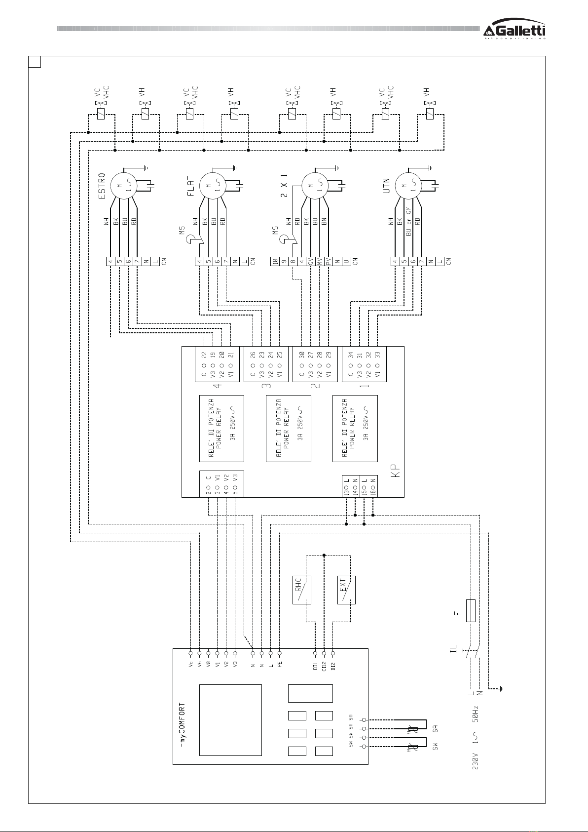
De vermogensinterface KP wordt gebruikt om tot 4 apparaten in
serie te schakelen op één bedieningspaneel.
Deze interface is geschikt om op een DIN rail gemonteerd te worden, die
zich gewoonlijk in de schakelkasten bevindt, en kan gebruikt worden
voor alle uitvoeringen van de serie èstro en voor de
luchtbehandelingsapparatenUTN(uitsluitendvoordemodellen06en08).
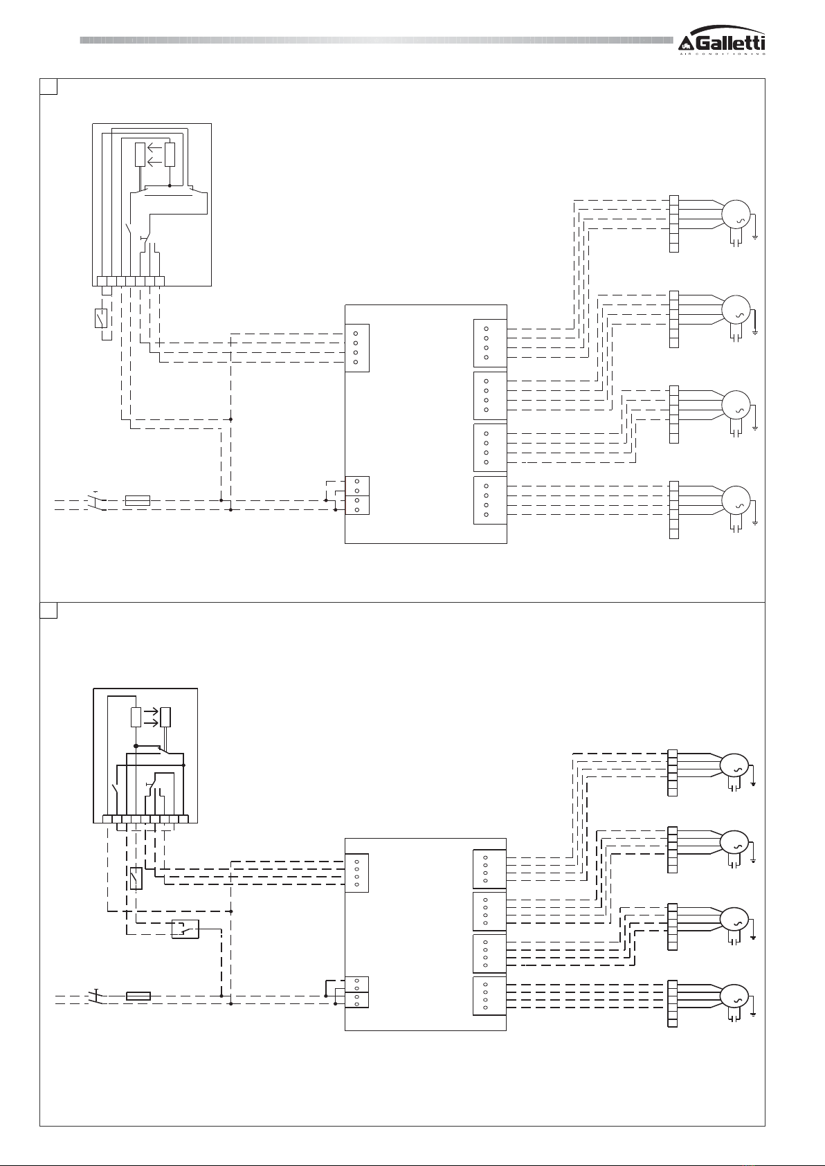
INSTALLATIE
- Klem de vermogensinterface KP op deDin rail.
- Sluit de elektrische kabels aan in afwezigheid van de
voedingsspanning zoals is aangegeven in de schema’s van de
afbeeldingen (van 1 tot 10) waarop het volgende wordt afgebeeld:
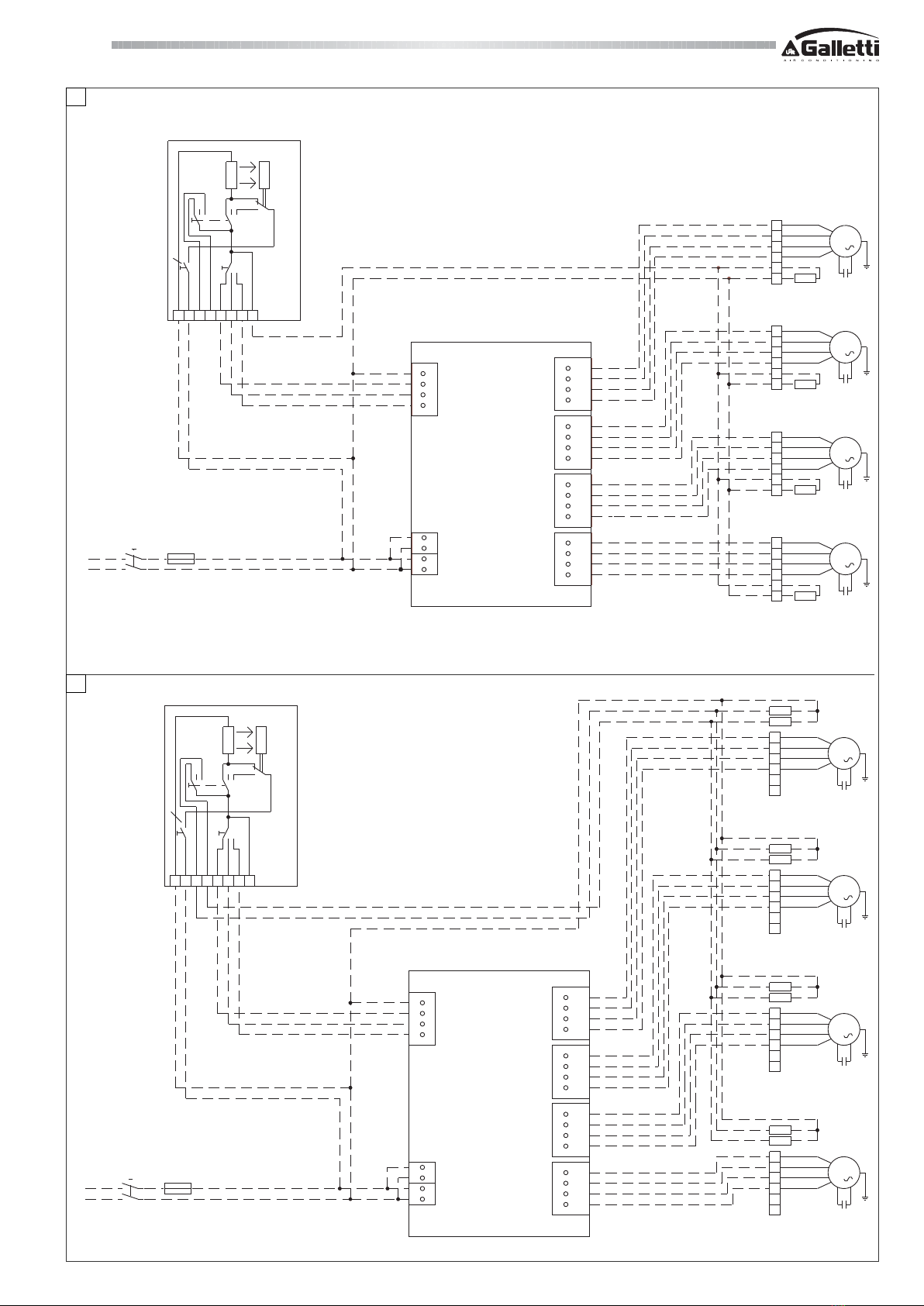
Afbeelding 1: TD (bedieningspaneel voor wandmontage) + KP.
Afbeelding 2: TDC (bedieningspaneel voor wandmontage) + KP.
Afbeelding 3: TD4T (bedieningspaneel voor wandmontage met 1
klep) + KP.
Afbeelding 4: TD4T (bedieningspaneel voor wandmontage met 2
kleppen) + KP.
Afbeelding: CDE (snelheidsschakelaar aan de wand) + TA
(elektromechanische omgevingsthermostaat) + KP.
Afbeelding 6: CDE + TA2 (omgevingsthermostaat met
seizoensschakelaar) + KP.
Afbeelding 7: CD (in de wand gebouwde snelheidsschakelaar) + TA
+KP.
Afbeelding 8: CD + TA2 + KP.
Afbeelding 9: MYCOMFORT BASE (wandbedieningspaneel met
microprocessor: automatische controle van de ventilatorconvector,
klep en elektrische weerstand) + KP.
Afbeelding 10: MYCOMFORT MEDIUM (wandbedieningspaneel
metmicroprocessor:automatische controle vande ventilatorconvector,
klep en elektrische weerstand) + KP.
Afbeelding 11: MYCOMFORT LARGE (wandbedieningspaneel met
microprocessor: automatische controle van de ventilatorconvector,
klep en elektrische weerstand) + KP.
Afbeelding 12: LED503 (wandbedieningspaneel met microprocessor:
automatische controle van de ventilatorconvector, klep en elektrische
weerstand) + KP.
De gearceerde aansluitingen dienen door de installateur verricht te
worden.
Voor iedere ventilatorconvector / heteluchtverwarmingsunit UTN in de
voedingslijn moet een omnipolaire netafsluiter aanwezig zijn van
overspanningscategorie III.
N.B. Sluit slechts één ventilatorconvector (fan-coil) per lijn aan (Max.1/
10 HP).
In de schakelschema’s worden de volgende afkortingen gebruikt:
De buitenafmetingen van de vermogensinterface KP zijn weergegeven
op afbeelding 13.
ALS VOLGT BESTELLEN
Vermogensinterface KP code EYKP.
NL
H
TECHNISCHEKENMERKEN
Voeding: 230 V -15% + 10%..60HZ
Uitgaande contacten: 4 x 3 A 250 V
Bedrijfstemperatuur: 0°C..+40°C
Grenswaarden 20%..80% Rv
vochtigheidsgehalte: Niet condenserend
Beschermingsklasse: IP30
Houder: Technopolymeer klasse VO
DIN mm 105 x 90 x 70
Gewicht: 265gr.

KPKP
KPKP
KP
6
FC66000758 - rev. 01
È severamente vietata la riproduzione anche parziale di questo manuale / All copying, even partial, of this manual is strictly forbidden
1
2
13 L
14 N
15 L
16 N
2
3
4
5
C
1
2
3
34
31
32
33
30
27
28
29
26
23
24
25
22
19
20
21
1
2
3
4
230V 1 50Hz
L
N
IL F
M
1
CN
9
8
7
6
5
4
M
1
CN
9
8
7
6
5
4
M
1
CN
9
8
7
6
5
4
M
1
CN
9
8
7
6
5
4
65N4321
ACC
KP
RD
BU/GY
BK
H
RD
BU/GY
BK
H
RD
BU/GY
BK
H
RD
BU/GY
BK
H
TC
TD
SF
C
S
T
N5613429
10
TDC
13 L
14 N
15 L
16 N
2
3
4
5
C
1
2
3
34
31
32
33
30
27
28
29
26
23
24
25
22
19
20
21
1
2
3
4
230V 1 50Hz
L
N
IL F
M
1
CN
9
8
7
6
5
4
M
1
CN
9
8
7
6
5
4
M
1
CN
9
8
7
6
5
4
M
1
CN
9
8
7
6
5
4
ACC
KP
RD
BU/GY
BK
H
RD
BU/GY
BK
H
RD
BU/GY
BK
H
RD
BU/GY
BK
H
T
C
S
TC
SF

7FC66000758 - rev. 01
KPKP
KPKP
KP
È severamente vietata la riproduzione anche parziale di questo manuale / All copying, even partial, of this manual is strictly forbidden
13 L
14 N
15 L
16 N
2
3
4
5
C
1
2
3
34
31
32
33
30
27
28
29
26
23
24
25
22
19
20
21
1
2
3
4
230V 1 50Hz
L
N
IL F
M
1
CN
9
8
7
6
5
4
M
1
CN
9
8
7
6
5
4
M
1
CN
9
8
7
6
5
4
M
1
CN
9
8
7
6
5
4
N46832 17
ACC
TD4T
VK-C-H
VK-C-H
VK-C-H
VK-C-H
RD
BU/GY
BK
H
RD
BU/GY
BK
H
RD
BU/GY
BK
H
RD
BU/GY
BK
H
KP
C
SF T
S
M
1
9
8
7
6
5
4
VK-H
VK-C
M
1
9
8
7
6
5
4
VK-H
VK-C
M
1
9
8
7
6
5
4
VK-H
VK-C
M
1
9
8
7
6
5
4
VK-H
VK-C
ACC
TD4T
13 L
14 N
15 L
16 N
2
3
4
5
C
1
2
3
34
31
32
33
30
27
28
29
26
23
24
25
22
19
20
21
1
2
3
4
230V 1 50Hz
L
N
IL F
RD
BU/GY
BK
H
RD
BU/GY
BK
H
RD
BU/GY
BK
H
RD
BU/GY
BK
H
CN
CN
CN
CN
KP
C
S
T
SF
N4683217
3
4

KPKP
KPKP
KP
8
FC66000758 - rev. 01
È severamente vietata la riproduzione anche parziale di questo manuale / All copying, even partial, of this manual is strictly forbidden
13 L
14 N
15 L
16 N
2
3
4
5
C
1
2
3
34
31
32
33
30
27
28
29
26
23
24
25
22
19
20
21
1
2
3
4
230V 1 50Hz
L
N
IL F
M
1
CN
9
8
7
6
5
4
M
1
CN
9
8
7
6
5
4
M
1
CN
9
8
7
6
5
4
M
1
CN
9
8
7
6
5
4
654321
RF
CDETA
RD
BU/GY
BK
H
RD
BU/GY
BK
H
RD
BU/GY
BK
H
RD
BU/GY
BK
H
TC
S
KP
32 1NN
5
13 L
14 N
15 L
16 N
2
3
4
5
C
1
2
3
34
31
32
33
30
27
28
29
26
23
24
25
22
19
20
21
1
2
3
4
230V 1 50Hz
L
N
IL F
M
1
CN
9
8
7
6
5
4
M
1
CN
9
8
7
6
5
4
M
1
CN
9
8
7
6
5
4
M
1
CN
9
8
7
6
5
4
65432 1
CDE
21NN
TA2
RF
C
S
SF T
RD
BU/GY
BK
H
RD
BU/GY
BK
H
RD
BU/GY
BK
H
RD
BU/GY
BK
H
KP
6

9FC66000758 - rev. 01
KPKP
KPKP
KP
È severamente vietata la riproduzione anche parziale di questo manuale / All copying, even partial, of this manual is strictly forbidden
7
13 L
14 N
15 L
16 N
2
3
4
5
C
1
2
3
34
31
32
33
30
27
28
29
26
23
24
25
22
19
20
21
1
2
3
4
230 / 1 / 50
L
N
IL F
M
1
CN
9
8
7
6
5
4
M
1
CN
9
8
7
6
5
4
M
1
CN
9
8
7
6
5
4
M
1
CN
9
8
7
6
5
4
3 2 1 N N
TA
RD
BU/GY
BK
H
RD
BU/GY
BK
H
RD
BU/GY
BK
H
RD
BU/GY
BK
H
T
KP
CD
S RL
4 1 2 3
C
RF
L
N
13 L
14 N
15 L
16
N
2
3
4
5
C
1
2
3
34
31
32
33
30
27
28
29
26
23
24
25
22
19
20
21
1
2
3
4
230V 1 50Hz
IL F
M
1
CN
9
8
7
6
5
4
M
1
CN
9
8
7
6
5
4
M
1
CN
9
8
7
6
5
4
M
1
CN
9
8
7
6
5
4
21N N
TA2
SF T
RD
BU/GY
BK
H
RD
BU/GY
BK
H
BU/GY
BK
H
RD
BU/GY
H
KP
RL
3214
S
C
CD
RF
BK
RD
8

KPKP
KPKP
KP
10
FC66000758 - rev. 01
È severamente vietata la riproduzione anche parziale di questo manuale / All copying, even partial, of this manual is strictly forbidden
9

11 FC66000758 - rev. 01
KPKP
KPKP
KP
È severamente vietata la riproduzione anche parziale di questo manuale / All copying, even partial, of this manual is strictly forbidden
10

KPKP
KPKP
KP
12
FC66000758 - rev. 01
È severamente vietata la riproduzione anche parziale di questo manuale / All copying, even partial, of this manual is strictly forbidden
11

13 FC66000758 - rev. 01
KPKP
KPKP
KP
È severamente vietata la riproduzione anche parziale di questo manuale / All copying, even partial, of this manual is strictly forbidden
12

KPKP
KPKP
KP
14
FC66000758 - rev. 01
È severamente vietata la riproduzione anche parziale di questo manuale / All copying, even partial, of this manual is strictly forbidden
13

15 FC66000758 - rev. 01
KPKP
KPKP
KP
È severamente vietata la riproduzione anche parziale di questo manuale / All copying, even partial, of this manual is strictly forbidden

40010 Bentivoglio (BO)
Via Romagnoli, 12/a
tel. 051/8908111
fax 051/8908122
www.galletti.it
Azienda certificata UNI EN ISO 9001 e OHSAS 18001
Company UNI EN ISO 9001 and OHSAS 18001 certified
Other manuals for KP
1
Table of contents
Other Galletti Recording Equipment manuals
Popular Recording Equipment manuals by other brands

Yamaha
Yamaha MOTIF RACK Music System Data list

Conrad Electronic
Conrad Electronic KeyMatic KM300RI operating instructions

Mitsubishi Electric
Mitsubishi Electric DX-TL910U Installation and operation manual

Tascam
Tascam US-224 Technical specifications

Roland
Roland Texart RT-640 Setup guide

Yamaha
Yamaha QX-3 owner's manual