G&G EDGE User manual

STRONG. SIMPLE. COMPACT.
800.285.6780 [email protected]
Rev Date 23 0610
IP69K
IP68
CERTIFIED
IK10
IMPACT
CERTIFIED
EDGE INSTALLATION MANUAL PAGE 1
WARNING
Fixtures must be installed by a qualied electrician in accordance with all applicable national and local electrical
and construction codes and regulations. Please read through this entire document before beginning the
installation.
Remove any xture from service if water or corrosion is observed inside the xture. Water and chemicals can
corrode metallic components and damage electrical circuits. Faulted electrical circuits can experience self-
heating which, while unlikely, may present a re hazard if left unchecked. This heating can also serve as an
ignition source for gasses generated by the corrosion of metals inside of the enclosure. Regularly scheduled
inspections are recommended to ensure safe operation.
RISK OF ELECTRIC SHOCK
• Turn power off before inspection, installation, or removal.
Electrical Requirements
• Suitable for wet locations.
• Follow all National Electric Codes (NEC) and local codes.
Notes
These instructions cover both the standard EDGE Power/Data Translator (PDT) conguration and PDT
conguration that includes the optional ColorWash controller. The steps which differ between these two
congurations are in separate sections, and it is only necessary to complete the ones that apply to the PDT
being installed.
Customer Service
For technical assistance and installation support please call 800-285-6780 x2 or email [email protected]

STRONG. SIMPLE. COMPACT.
Rev Date 23 0610
800.285.6780 [email protected]
EDGE INSTALLATION MANUAL PAGE 2
Supplied Materials
1G&G EDGE Series Fixtures
2Leader Cable(s)
3Jumper Cable(s)
4Termination Plug(s)
5Mounting Brackets (Ceiling or Wall)
6G&G EDGE Power/Data Translator (PDT) [Includes controls, power distribution and drivers.]
1EDGE Standard Fixture
EDGE Leader Fixture
2 3
Leader Cable Jumper Cable
4Termination Plug 6EDGE Power Data/Translator Box
5Mounting Brackets

STRONG. SIMPLE. COMPACT.
Rev Date 23 0610
800.285.6780 [email protected]
EDGE INSTALLATION MANUAL PAGE 3
NOTICE TO INSTALLERS
G&G EDGE lights must be installed on the building in accordance with the layout that is provided with the
system. Each string of lights must be connected to the LED output on the PDT as specied in the layout
documents. Failure to follow the layout or connecting a string of xtures to the wrong LED output will lead to
lighting effects being generated in an erratic manner.
There are 2 different types of xtures used in the EDGE lighting system. The rst “LEAD” (LE) xture on each
leader uses a 6-pin input connector, while all other “THRU” xtures in each string have 4-pin connectors. THRU
xtures have a gray connector shell on the input end and a black connector shell on the output end, while
LEAD xtures have black connector shells on both ends. Care must be taken to ensure that the LEAD and THRU
xtures are installed in the correct locations.
The jumpers between xtures have 4-pin connectors that mate to the output and input connectors on the THRU
xtures. A terminating cap must be plugged into the output end of the last xture in each string. This cap seals
the last xture in the chain. Failure to install this cap will lead to premature xture failure due to water ingress.
Refer to your site-specic xture layout and wiring diagram prior to installation. An example is shown below.
If you have any questions about the layout, contact G&G support prior to beginning installation.
CLEAR WATER
EXPRESS
FELIPE RAMIREZ
05/17/2023
CLEAR WATER
EXPRESS
FELIPE RAMIREZ
05/17/2023
CLEAR WATER
EXPRESS
FELIPE RAMIREZ
05/17/2023

STRONG. SIMPLE. COMPACT.
Rev Date 23 0610
800.285.6780 [email protected]
EDGE INSTALLATION MANUAL PAGE 4
Mounting the EDGE Fixtures
• EDGE series wet location xtures are typically surface mounted (Walls, Softs, etc.). If mounting to the
building softs, it is recommended to mount the xtures on the outer edges of the softs to maximize
the distance from the building walls. Fixtures should be aimed downward and slightly inward toward the
building for the best effect.
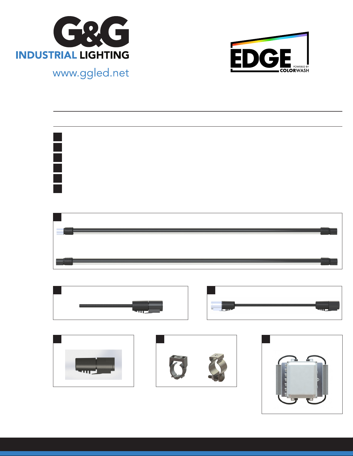
• Each xture has an input (male) and output (female) end. The end of the xture with the product
identication label is the input end. The xture must be installed with the input end oriented in the
direction of your incoming power source or leader cable.
• The location of the xtures must follow your site-specic layout.
• For long linear runs, G&G recommends using a chalk line or laser to mark the mounting bracket locations.
• 2’, 4’, and 6’ xtures require at least two mounting brackets. Brackets should be installed near the ends of
the xtures. 8’ models require three brackets with the third bracket being installed near the center of the
light xture.
• This product makes use of a push-click connector system. An audible click upon insertion of the connector
indicates that the connector is fully seated. Failure to fully seat connectors can lead to cable and xture
damage during use.
Connect the power leader cable to
the input connector (male) on the LED
xture. To do this, align the connectors,
push inward, and listen for the audible
click sound that indicates that the
connector is fully seated.
When daisy chaining xtures continue mounting xtures and
attach jumper cables as needed using the same push-click
connection method as the leader cable.
Mount the xture(s) in their specic location using the Surface Mount Bracket to afx directly to the ceiling or softs.

STRONG. SIMPLE. COMPACT.
Rev Date 23 0610
800.285.6780 [email protected]
EDGE INSTALLATION MANUAL PAGE 5
CONTROLLER INSTALLATION & ELECTRICAL CONNECTIONS
Notes
• The EDGE Power/Data Translator (PDT) board distributes power to the LED xtures and the optional
ColorWash control board.
• If installed, the ColorWash control board manages network connectivity, show/effect generation
and other controls.
Power Circuits / Wiring / Circuit Breakers
The EDGE system is compatible with 120V and 277V single phase power systems. The EDGE system needs to
have power supplied to it from the building’s breaker box to the three AC VOLTAGE IN terminals (LINE, NEUT,
GRND) at the bottom of the board below the driver fuses. The input circuit shall be supplied with a 20A breaker
on 120V systems or a 15A breaker on 277V systems.
Power/Data Translator (PDT) Board
• The AC Input terminal blocks (120V/277V) feed 1 or 2
externally mounted AC/DC drivers, depending upon
the PDT conguration. These are installed and wired
at the factory.
• The drivers supply 48VDC to the 4 LED Output
terminal blocks. See table on page 6 for maximum
xture connection details.
• One PDT board represents one DMX512 universe;
the maximum number of xtures that can be run
off one universe depends on the amount of power
available from the drivers.
• Each leader cable must be terminated at its own
LED output terminal block.
• A Reset (Boot) Button S1 is located below the
Single Driver Jumper terminals on this board.
See the picture to the right.

STRONG. SIMPLE. COMPACT.
Rev Date 23 0610
800.285.6780 [email protected]
EDGE INSTALLATION MANUAL PAGE 6
Pixel Information
• EDGE xtures use 4 DMX channels per pixel in an RGBW conguration for each 2-foot-long pixel, but only
the rst three channels (RGB) are used (EDGE xtures only contain red, green and blue LEDs).
• When installing the system, check the length of the string of xtures for each part of the building where the
xtures will be installed. Do not connect more than 88 feet of xtures to the 1A LED output, and do not
connect a total of more than 88 feet of xtures to the Driver 1 outputs (1A and 1B). The same limits apply
to the Driver 2 outputs (2A and 2B). The B outputs (1B and 2B) have a limit of 40 feet. G&G recommends
that the split be as even as possible within these limits. For example, if possible, split 88 feet into a 48-foot
string and a 40-foot string, or split 72 feet into two 36-foot strings.
• Please contact the G&G support team before making any changes to the layout of xtures and leaders.
The system has limits on how many xtures and pixels can be connected to each driver and each output,
and the support team will be able to tell if a change to the original layout will work or not.
• Consult the following table for the maximum lengths for each output and the mapping of EDGE pixels to
each LED output.
LED
Output
DMX Start
Address
Maximum Length
of All Fixtures
Maximum Number
of Pixels
First
Pixel
Last
Pixel
1A 1 88 Feet 44 1 44
1B 177 40 Feet 20 45 64
2A 257 80 Feet 44 65 108
2B 433 40 Feet 20 109 128

STRONG. SIMPLE. COMPACT.
Rev Date 23 0610
800.285.6780 [email protected]
EDGE INSTALLATION MANUAL PAGE 7
LED Fixture Electrical Connections
• The LED Output connectors on the circuit board inside the EDGE PDT are labeled 1A, 1B, 2A, and 2B.
• The system layout that is included with the system identies which leaders connect to which string of lights.
For instance, leader 1A must be connected to output 1A, and leader 2A must be connected to output 2A.
Failure to make the correct connections will lead to lighting effects being generated in an erratic manner.
• To connect the leader cables to the LED Output terminals, remove 2-3” of the black outer insulator of the
leader cable. Strip 3/8” of insulation off the blue, red, white, and black wires. Connect these wires to the
“LED OUTPUT” terminals as shown in the table and photo below. Trim back the green wire and the shield
around the blue and red wires; they are not used in the EDGE system.
LED Output
Terminal
Leader Cable
Wire Color
D- (Data Minus) Blue
D+ (Data Plus) Red
V- (0 VDC) Black
V+ (48 VDC) White

STRONG. SIMPLE. COMPACT.
Rev Date 23 0610
800.285.6780 [email protected]
EDGE INSTALLATION MANUAL PAGE 8
DMX CONFIGURATION
If the ColorWash option is installed, please skip this section and proceed to the Control Board and Network
Connectivity sections on page 9.
Data Input
• The DMX connections bring xture data into the EDGE PDT board and optionally pass the data along to
other DMX devices.
• Terminal blocks are provided for connecting the three discrete wires in the data cable; these are marked on
the board next to the terminals (D+, D-, and COM).
• Optionally, the RJ45 (8P8C) connector can be used instead of the three terminals if the DMX source
supports this type of cabling. (XLR-to-RJ45 adapters are available from electronics distributors like
Newark.)
• A DMX terminator switch is provided on the PDT board. It is set to terminated at the factory. Move this
switch to its other position if termination is not required. An indicator for the termination being active
is provided near the termination switch. DMX Installation is now complete. Disregard the ColorWash
Installed Option section next.

STRONG. SIMPLE. COMPACT.
Rev Date 23 0610
800.285.6780 [email protected]
EDGE INSTALLATION MANUAL PAGE 9
COLORWASH INSTALLED OPTION
Control Board
• The required connections to the PDT Board are installed at the factory.
• A Reset Button is located on this board next to the ethernet port J1.
• Ethernet Network connectivity to ethernet port J1 is required to adjust the settings stored on the controller.
Network Connectivity
In order to congure the ColorWash portion
of your EDGE system, it must have a
connection to the internet. The connection
is made using the RJ45 connection port on
the control board. This ethernet connection
must have access to outside networks.
The network cannot be restricted to local
connections only. Enterprise networks may
block outgoing connections using a rewall.
If this is the case, the following ports must
be opened for outbound connections to
allow the device to connect to our servers:
User Interface
• In order to access the ColorWash system, you will need to create an account on the ColorWash dashboard
at https://dashboard.colorwash.app.
• Requests for new accounts can also be sent to our support team at [email protected] or (800)-285-6780.
You will need to provide our team with a valid email address. An invitation link from colorwash@colorwash.
app will be sent to that email. Click the Create Account button to access the registration form.
• After your account has been created, you can access the dashboard and adjust the settings for your system.
• For information about conguring your system using the dashboard, please refer to the ColorWash
Dashboard User Guide. This can be found on the G&G website at www.ggled.net.
QUESTIONS?
Please contact G&G Support at 800.285.6780
Port TCP UDP Usage
31314 Initial device-server connection
993 Fall-back device-server connection #1
443 Fall-back device-server connection #2
80 Fetch device rmware
Table of contents
Other G&G Lighting Equipment manuals
Popular Lighting Equipment manuals by other brands

Westfalia
Westfalia Wetelux 951409 Original instructions

Cooper Lighting Solutions
Cooper Lighting Solutions Fail-Safe FCC installation instructions

Alkalite
Alkalite Octopod installation guide

Jandy
Jandy APURE35 Installation and operation manual

AquaScape
AquaScape 84057 installation instructions

LiteGear
LiteGear Auroris X System quick start guide

Westfalia
Westfalia 96 20 13 Original instructions

Behringer
Behringer EUROLIGHT MOVING HEAD MH710 quick start guide

Velleman
Velleman HQ POWER VDLPROM2 user manual

MJ LED LIGHTNING
MJ LED LIGHTNING MJ-B380 user manual

PURElight
PURElight Pixelbar Switch user manual

LYTEQUEST
LYTEQUEST XPERFORMER BAR user manual