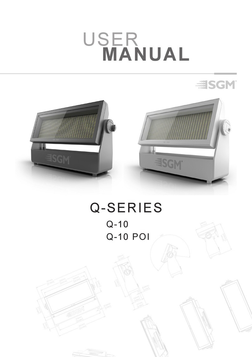
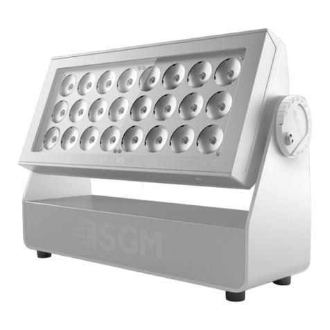
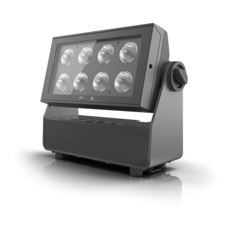
SGM P Series User manual

USER
MANUAL
P-SERIES
P-6
P-6 POI

2
P-6 Series dimensions
This manual covers installation, use, and maintenance of the SGM P-6 Series.
A digital version is available at www.sgmlight.com, or upon request via [email protected].
P-6 SERIES
USER MANUAL REV. C
© 2018 SGM Light A/S®. The information in this document is subject to change without notice.
English edition
All dimensions in millimeters and inches. Drawing not to scale.
P-6
P-6 POI

3
Contents
Safety information .....................................................................................................................4
Overview .................................................................................................................................5
Preparing for installation ............................................................................................................6
Installing / rigging the P-6 Series .................................................................................................6
Tilt Lock ..................................................................................................................................7
Connecting AC power ................................................................................................................8
...............................................................................................................8
............................................................................................
......................................................................................10
......................................................................................................11
.................................................................................................11
...................................................................................................................12
.........................................................................................................................13
RDM ......................................................................................................................................14
.....................................................................................................................14
...........................................................................................15
Accessories ...........................................................................................................................18
Maintenance ...........................................................................................................................20
.........................................................................................................21
.......................................................................................................................21
.....................................................................................................21
User Notes .............................................................................................................................22
User Notes .............................................................................................................................23

4
WARNING!
Read the following safety precautions carefully before unpacking, installing,
powering, or operating the device.
SGM luminaries are intended for professional use only. They are not suitable for household use.
Les luminaires SGM sont impropre à l’usage domestique. Uniquement à usage professionnel.
This product must be installed in accordance with the applicable installation code by a person familiar with
the construction and operation of the product and the hazards involved.
Ce produit doit être installé selon le code d’installation pertinent, par une personne qui connaît bien
le produit et son fonctionnement ainsi que les risques inhérent.
Safety information
•
•
•
•
•
DANGER! Risk of electric shock. Do not open the device.
•
•
•
•
•
•
•
•
CAUTION:
•
•
•
corrosion-resistant hardware.
•
•
•
it must have a minimum gauge of 4 mm.
WARNING! Take measures to prevent personal injury.

5
P-6 Series features:
•
•
•
•
•
•
•
•
•
•
•
Overview
P-6 POI
B
A
A: 24xRGB + 24W LEDs
B: P-6 Tilt lock
C: Cooling fans
D: Control panel (POI n/a)
E: OLED Display (POI n/a)
F: Rubber feet (POI n/a)
G: GORE-TEX membrane
H: DMX in and out
I: Power in and out
J: Handle
K: Barndoors attachment points (x2)
L: Safety wire attachment point
M: Holes for Omega bracket / M-10 screws (x6)
N: P-6 POI Tilt lock (POI only)
O: LED indicator (POI only)
C
O
N
I
H
L
M
G
DE
J
K
P 6
F

6
Unpacking
•
•
•
•
•
Location / application
•
•
When selecting a location for the device, ensure that:
•
•
•
• For wireless DMX or standalone operation
• For cabled DMX operation
Transportation
Preparing for installation
PLEASE NOTE!!
The 1/4-turn fasteners are only locked when turned fully clockwise.
rigging the P-6 POI” on page 16.
Installing / rigging the P-6 Series
106 mm
[ 4,2in ]
Ø 18 mm
[ 0,7in ]
Figure 2: P-6 Series locking points

7
WARNING! Always secure an elevated P-6 with a safety wire
•
• Have a minimum gauge of 4 mm.
•
CAUTION!!
• Always use a safety wire.
• Make sure the slack of the safety wire is at a minimum.
• Never use the handle for secondary attachment.
Rigging process using SGM Omega brackets
1.
o f
2.
3. -
a
4.
5.
6. -
7.
Holes for omega bracket
Omega bracket
Figure 3: Base with omega bracket
Figure 4: Safety wire attachment point
1.
2. Adjust the tilt to the angle desired and hold it.
3.
enough.
CAUTION!!
Angle indicator
The angle indicator in the wheel shows the current angle of inclination.
NOTE: In POI versions, SGM provides a POI Spanner with a pig-nose key for tilt adjustment. Either use the large or the small
Tilt Lock
Pitch angle
indicator

8
Connecting AC power
•
•
•
PLEASE NOTE!
CAUTION!!
The fixture must be grounded/
earthed and be able to be isolated
from AC power. The AC power
supply must incorporate a fuse or
curcuit breaker for fault protection.
Color
Black
White
green/yellow
Conductor
live
neutral
ground (earth)
Symbol
or
L
N
Wire
Figure 6: P-6 Power cable
The fixture must be grounded/
earthed and be able to be isolated
from AC power. The AC power
supply must incorporate a fuse or
circuit breaker for fault protection.
Color
Black
White
green/yellow
Conductor
live
neutral
ground (earth)
Symbol
or
L
N
Wire
Figure 7: Connecting AC Power
DMX
8
ESC ENTER
6CH MODE
(14)
Figure 8: OLED display and control panel

Using the display panel
•
•
•
Display
B - DMX address.
Error Indicator
Shortcuts
•
•
•
•
connectors suitable for outdoor use.
For POI versions, please refer to pages 16-17 to see how to connect DMX and AC power.
Connecting a wireless transmitter
•
• Press the connect button on the wireless transmitter.
•
Note: for POI versions, refer to page 17 to see how to connect to a wireless transmitter.
Disconnecting a wireless transmitter
menu.
Note: for POI versions, refer to page 17 to see how to disconnect from a wireless transmitter.
Signal priority
cabled DMX over wireless DMX.
NOTE: In POI version with wireless, the DMX signal strength can only be checked through RDM.
Connecting to a DMX control device
Figure 9: Display view
DMX
8
6CH MODE
(14)
A B C D
E

10
About DMX
-
PLEASE NOTE:
• Standard microphone cable is not suitable for transmitting DMX.
•
•
DMX Start address
NOTE!!
Set/edit DMX address
DMX modes
DMX
8
6CH MODE
(14)
DMX address
Next
available
DMX
Figure 10: Set/edit DMX address

11
P-6 Connection Diagram
·
·
Max. 32 units/DMX line
1 2 xx
CONNECTION DIAGRAM
P
•
6
SGMLight A/S· Sommervej 23 · 8210 Aarhus V · Denmark
Tel +45 70 20 74 00 · info@sgmlight.com· www.sgmlight.com
SGM_P-6 (Rev.2)
115 - 277V AC
50-60 Hz
450 W
115 - 277V AC
50-60 Hz
450 W
115 - 277V AC
50-60 Hz
450 W
DMX Termination
on last fixture DMX out
DATA
GND
DATA -
DATA +
120 Ohm +/- 5%
Max. 6 units/16 A circuit
P 6 P 6P 6
Figure 11: P-6 connection diagram (see page 17 for POI)
scenes with its own RGB and shutter settings.
STANDALONE.
Using standalone operation
Figure 12: Standalone operation
Setting a static color manually

12
Factory default
•
•
•
•
•
•
•
Effects
Color temperature correction
Ultra high-speed strobe effect
Beam angle
Flipping the OLED display (POI n.a.)
the same time.
Setting the OLED display saver (POI n.a.)
brightness.
Setting the fan mode
NOTE: In POI version, the fan mode adjustment is possible through RDM.
Pixel 1
Pixel 3
Pixel 5
Pixel 4
Pixel 2
Pixel 6

13
Level 1 Level 2 Level 3 Function
Mode Select Mode - Select DMX mode
Info -
-
Serial Number -
RDM ID -
DMX View
Mainboard
LED Left
LED Right
Base
Power on time -
LED On Time -
Errors -
Settings
Signal strength
2. Stand-alone
Disable
Enable
Standard
Silent
-
Manual Red
Green
Blue
Run Program
-
Editor Program
Scene
Red
Green
Blue
Shutter
Test Off -
Automated Test -
-
Control menu

14
Supported RDM functions
RDM functions
RDM
Name Sensor Type
Mainboard
LED Left 1
LED Left 2
LED Left 3
LED Right 1
LED Right 2
LED Right 3
Name Sensor Type
Other
Other
Other
Other
Other
Base
PID Actions allowed Name
- Device Label
- Manufacturer Label
-
-
-
- Sensor Value
-
- Device Hours
PID Actions allowed Name
-
-
-
-
- Reset Device
GET Serial Nr.
GET / SET
Please note:
Sensors
Please note: The table is subject to change without notice.
Troubleshooting
Problem Potential cause(s) Remedies
Main fuse is blown.
Power was turned off.
DMX cables were disconnected.
Install a XLR 120ohm DMX termination at the end of
The minimum values are out of calibration.

15
Physical differences
PLEASE NOTE!!
Remote Device Management (RDM) requires a correct DMX cabled installation and termination.
When setting addresses through RDM and using USB dongles, disable the USB selective suspend to ensure a proper
voltage on the DMX link. If any lag or trouble occurs when addressing, decrease the cable length range to <12 m. and only
LED Indicator
• Static green:
• Flashing green:
• Flashing orange (when using the magnet):
•
• Off:
SGM Addressing Tool
POI Permanent Outdoor Installation
Figure 14: P-6 POI LED indicator
P-6 POI
B
A
A: 24xRGB + 24W LEDs
B: P-6 Tilt lock
C: Cooling fans
D: Control panel (POI n/a)
E: OLED Display (POI n/a)
F: Rubber feet (POI n/a)
G: GORE-TEX membrane
H: DMX in and out
I: Power in and out
J: Handle
K: Barndoors attachment points (x2)
L: Safety wire attachment point
M: Holes for Omega bracket / M-10 screws (x6)
N: P-6 POI Tilt lock (POI only)
O: LED indicator (POI only)
C
O
N
I
H
LM
G
DE
J
K
P 6
F

16
Figure 18: P-6 POI base with dimensions
POI Spanner
POI Tilt lock
1.
2.
3.
4.
Installation and rigging the P-6 POI
the base.
-
information on correct POI rated mounting.
B
C
AA: Magnet
B: Small pig-nose key
C: Large pig-nose key
Figure 16: POI Spanner
Figure 17: P-6 POI Tilt lock
Connecting DMX and AC power in POI
PLEASE NOTE!!
• Standard microphone cable are not suitable for transmitting DMX.
•
•
•

17
1 2 XX
Max. 32 units/DMX line
XLR pin out
5 PIN XLR
DATA
GND
DATA - DATA +
Shield / GND
White / DMX in / Data -
Red / DMX in / Data +
Shield / GND
Black / DMX out / Data -
Yellow / DMX out / Data +
Junction box
DMX cable
Shield / GND
White / DMX in / Data -
Red / DMX in / Data +
Shield / GND
Black / DMX out / Data -
Yellow / DMX out / Data +
Junction box
DMX cable
DMX termination last junction box
DMX cable
White / DMX in / Data -
Red / DMX in / Data +
Black / DMX out / Data -
Yellow / DMX out / Data +
120 Ohm +/- 5%
Figure 19: Connecting DMX and AC Power in P-6 POI
SGM SGM SG
Shield
WireColor
White
Red
Conductor
Black
Yellow
Ground
DMX IN: Data -
DMX IN: Data +
DMX OUT: Data -
DMX OUT: Data +
SGM POI DMX Cable
Connecting a wireless transmitter in POI
1.
transmitter.
2.
Disconnecting a wireless transmitter in POI
P-6 POI connection diagram

18
Accessories
Barndoors
1.
2.
3.
Filter frames
•
•
•
•
•
Upper lock pins Attachment
points
Lower
lock pins
Filter frame front view Filter frame back view P-6 with lter frame
Figure 20: P-6 Barndoors
Figure 21: P-6 Filter frames
PLEASE NOTE!!

For further information and other possibilities visit www.sgmlight.com or contact your local SGM dealer.
Anti-glare shields
• Full anti-glare shield
• Half anti-glare shield
Note: The anti-glare shields are suitable for both permanent outdoor and indoor installations.
Figure 22: Full and half anti-glare shields

20
SGM Vacuum Test kit
SGM Uploader cable
•
•
• Through RDM.
Cleaning
connectors.
Maintenance
Figure 24: SGM Firmware tool
Figure 22: SGM Vacuum Test Kit
Figure 23: SGM Uploader cable
Other manuals for P Series
3
This manual suits for next models
2
Table of contents
Other SGM Lighting Equipment manuals
Popular Lighting Equipment manuals by other brands

Luminaire led
Luminaire led LVP1212 LED Series installation guide
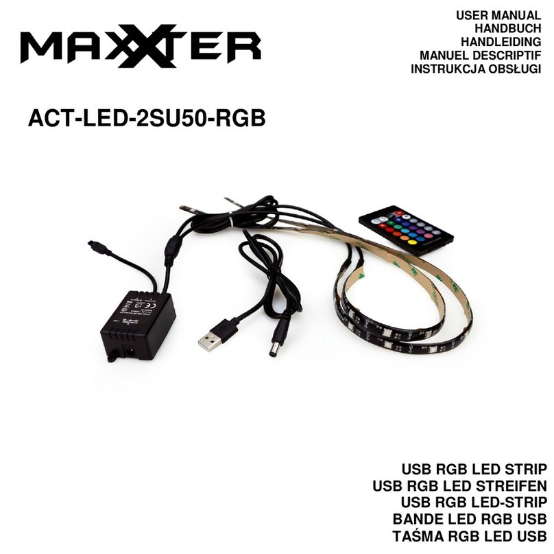
MAXXTER
MAXXTER ACT-LED-2SU50-RGB user manual
Original BTC
Original BTC DAVEY LIGHTING 7202 instruction manual
LaMotte
LaMotte WaterLink SpinTouch 3580 quick start guide
THORLABS
THORLABS SLS303 user guide
iSolution
iSolution iMove 350SR user manual
