GANTERUD L3 User manual

ENG
www.ganterud.se
User manual
Version 2.0. 2022
GANTERUD L3

2
Doc. no.: 220929-001
EC Declaration of Conformity
According to 2006/42/EC, Annex 1, Sections 1 and 4 (AFS 2008:3, Annex 2A).
ORIGINAL
Hereby declares that
Manufacturer / representative
: Ganterud Lifting Solutions AB.
Address : Frögatan 10, SE 653 43 Karlstad.
Machine / installation : Lifting yoke L3.
Serial number : 1215100-0000.
Corresponds where applicable with the following directives:
The Machinery Directive 2006/42/EC, Annex 1, Sections 1 and 4.
The EMC Directive 2014/30/EU.
The Low Voltage Directive 2014/35/EU.
Satises where applicable the requirements in standards and specications
listed below:
SS EN ISO 12100-2010 SS EN 13155+A2:2009
SS EN 61000-6-4 SS EN 60204-1
SS EN 61000-6-2 ELSÄK-FS 2008:1-4
Place and date
Authorised signatory
Address
Name in block capitals
Frögatan 10, SE 653 43 Karlstad
Kristoer Ganterud
Karlstad, 29/09/2022

1 Introduction......................................................................4
1.1 About this manual............................................................. 4
1.2 Disclaimer............................................................................... 4
1.3 Warranty and complaints............................................ 4
1.4 Contact information........................................................ 4
2 Safety ..................................................................................5
2.1 Denition of safety levels............................................ 5
2.2 Signs on the lifting yoke.............................................. 5
2.3 General.....................................................................................6
2.4 Incorrect handling............................................................ 7
2.4.2 Lifting with one hook................................................. 7
2.4.1 Load imbalance.............................................................. 7
2.4.3 Impact................................................................................... 7
2.4.4 Centring ..............................................................................8
2.4.6 Relieving the load from the lifting yoke......8
2.4.5 Long load ..........................................................................8
2.5 Safety during operation...............................................9
3 Description .................................................................... 10
3.1 Overview................................................................................10
3.2 Lifting capacity ................................................................10
3.2.1 Lifting table.......................................................................11
3.2.2 Levelling expressed as height dierence
12
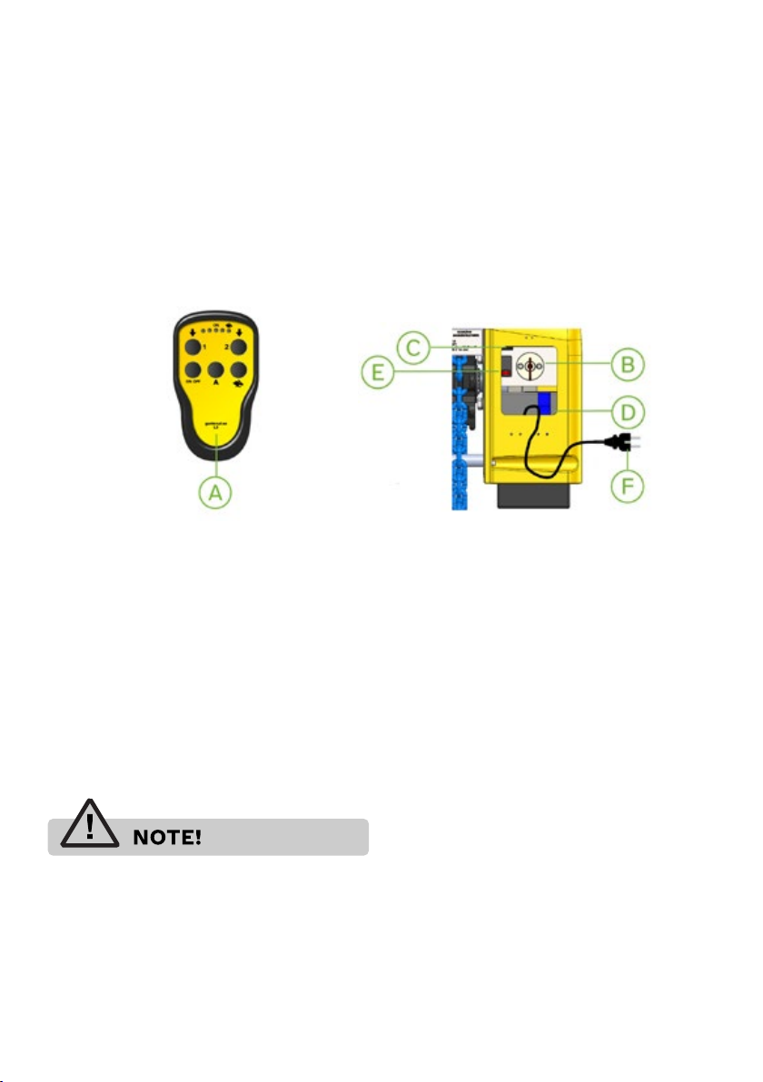
3.3 Remote control. ...............................................................13
3.4 Intended use......................................................................13
3.5 Disposal.................................................................................13
Contents
4 Operation.........................................................................14
4.1 Daily inspection................................................................14
4.1.1 Before use.........................................................................14
4.1.2 After use.............................................................................14
4.2 Operating the lifting yoke.........................................15
4.2.1 Preparations....................................................................15
4.3 Calibration of the neutral position......................16
4.5 Synchronising new remote control with
lifting yoke....................................................................................17
5 Tandem operation...................................................... 18
6 Maintenance.................................................................20
6.1 Charging the batteries in the lifting yoke ....20
6.2 Replacing batteries in the remote control.20
6.4 Storage and transport.................................................21
6.5 Cleaning................................................................................21
6.6 Inspection............................................................................21
7 Technical data ............................................................. 22

4
1.1 About this manual
Keep this user manual for future use – the manual must be available when using the lifting yoke.
The latest version of the manual can also be found on Ganterud Lifting Solutions AB’s website, www.
ganterud.se. The lifting yoke is accompanied by an individual test report from the lifting yoke’s static
testing.
1.2 Disclaimer
Ganterud Lifting Solutions AB is not liable or bound by guarantees if these instructions are not adhered
to during operation, transport, storage or maintenance.
Ganterud Lifting Solutions AB reserves the right to modify the product, component parts, specications
and the content of this manual without prior notication.
Ganterud Lifting Solutions AB accepts no liability for any interventions in or modications to the product
that have been made without Ganterud Lifting Solutions AB’s written consent. The product’s type
approval will cease to apply in the event of any modications.
1.3 Warranty and complaints
Ganterud Lifting Solutions AB guarantees that the product will be free from defects for a period of one
(1) year from the date of delivery, provided the lifting yoke has been used, serviced and maintained in
the prescribed manner.
During the warranty period, Ganterud Lifting Solutions AB will repair or replace products and
component parts that are returned to Ganterud Lifting Solutions AB with shipping charges prepaid.
Ganterud Lifting Solutions AB reserves the right, on a case by case basis, to determine whether the
warranty is valid or not.
The warranty will be invalid if the product or its component parts have been subjected to incorrect use,
misuse, negligence or accidents.
The warranty will be invalid if the product has been modied or repaired by an unauthorised party as
per the specication in this manual.
The warranty will become invalid if the product has been altered or modied using components other
than those specied by Ganterud Lifting Solutions AB.
The purchaser must inspect the product promptly following receipt, and must notify Ganterud Lifting
Solutions AB’s head oce in writing about any claims, including claims regarding breach of warranty,
within thirty days after the purchaser has discovered, or ought to have discovered, the facts on which the
warranty claim is based.
Failure by the purchaser to submit written notication of a warranty claim within this time period will be
deemed to be a waiver of such claim.
1.4 Contact information
Ganterud Lifting Solutions AB, www.ganterud.se
For support or other information about the product, please contact Ganterud Lifting Solutions AB:
e-mail: [email protected]
Tel. during oce hours: +46 70281 20 08
1 Introduction

2 Safety
2.1 Denition of
safety levels
2.2 Signs on the lifting yoke
• Rating plate, CE marking
• Warning of the risk of crushing between chain
and metal housing.
• Max. load
• Max. load imbalance
• Max. chain angle
• Instructions for correct operation
• Lifting table
Species an immediately hazardous
situation that, if not avoided, will result in
death or serious injury.
Species a potentially hazardous situation
that, if not avoided, may result in minor
or moderate injury as well as damage to
property.
Species a potentially hazardous situation
that, if not avoided, may result in death or
serious injury.

6
2.3 General
Incorrect use may result in death or serious injury to a
person and/or damage to property.
• Carefully read through this manual before
using the lifting yoke.
• The lifting yoke may only be operated by
personnel who are trained and possess
sucient knowledge about the lifting yoke.
• The lifting yoke may only be operated by
personnel standing on a rm surface and who
have a clear view of the load.
• The lifting yoke is only intended for lifting
loads using hooks/shackles. Any other use is
prohibited.
• All lifting aids used together with the lifting
yoke must be provided with built-in scales.
Alternatively, the weight must be known and
documented, in order to prevent overloading
of the lifting yoke.
• The lifting yoke must not be used if the xed
protection covering rotating parts is damaged
or has been removed.
• Take care when handling the lifting yoke.
There is a risk of crushing between the chain
and the metal housing.

2.4 Incorrect handling
2.4.1 Load imbalance
2.4.3 Impact2.4.2 Lifting with one hook
The lifting yoke must not be imbalanced.
See lifting table for maximum load imbalance.
The lifting yoke may be damaged in the event of
an impact.
Both hooks must be used when lifting! The lifting
yoke must not be used for lifting and hoisting
using only one hook.
The chain must be tensioned on both sides before
lifting may be carried out.

8
2.4.5 Long load
2.4.6 Relieving the load from the lifting yoke
The chain angle must be as wide as possible,
although not exceeding 60°, to reduce the strain
on the lifting yoke in the event the load should
start to swing.
Lift the load rst, level once it is freely suspended.
The load must be horizontal when placed on
a at surface, or the load on both attachment
points must be relieved at the same time.
2.4.4 Centring
The lifting yoke must be centred above the load’s
centre of gravity within a specied margin of
error, in accordance with the lifting table.
The chain must be tensioned on both sides before
lifting may be carried out.

2.5 Safety during operation
Incorrect handling or a lack of control can
expose personnel to danger of death!
• Perform a daily inspection of the lifting yoke
before each use.
• Perform a load inspection before each lift.
• The lifting yoke may only be operated using
remote control, where the operator is standing
on a rm surface and has a clear view of the
load.
• If there are several lifting yokes on site, make
sure that the registration number on the side
of the remote control corresponds with the
registration number on the lifting yoke’s rating
plate.
• The lifting yoke is not intended for lifting
people. Do not stand on or under a suspended
load.
• Connect the hook/shackle directly to the
load, or via a chain or sling to the load.
• Check that the safety lock on each hook/the
pin on each shackle is properly locked.
• The entire load must be securely lashed to
avoid falling items when lifting.
• The chain must be tensioned on both sides
before lifting may be carried out.
• Lift the load slowly to minimise acceleration
forces.
• Transporting and movement during lifting or
lowering are associated with danger. Adapt
the speed to minimise the danger to people
and equipment.
• Keep a careful lookout for people moving
within the risk zone. Make them aware that
transport is in progress.
• Observe the load constantly during operation.
• Make sure that nobody is at risk of being
crushed by the load when it is lowered, or
pushed in the event the load should start to
swing.

10
3 Description
3.1 Overview
The GANTERUD L3 is a radio-controlled lifting
yoke that is used for precision adjustment of
heavy objects, such as structural elements,
beams, roof trusses, etc., when lifting with a crane
or other lifting equipment.
The lifting table applies during normal usage. In
the event of any uncertainty, scales/load cells
must be used to measure the load at each end of
the chain.
A. Remote control.
B. Motor switch. Breaks the power supply to the motor. Must be switched o when the
batteries are being charged.
C. Battery charger.
D. Batteries.
E. Battery indicator. Indicates battery status. 25 - 100%.
F. Cable for battery charger. Connected to 230V AC 50 Hz for charging batteries.
The lifting yoke is powered by a built-in electrical
motor equipped with a rechargeable battery, and
can be used with most types of cranes and lifting
devices.
3.2 Lifting capacity
Exceeding the maximum chain angle or the
maximum lifting capacity will damage the
equipment.

3.2.1 Lifting table
GANTERUD L3
Lifting capacity: Max. 3 tonnes
Load imbalance capacity Max. 500 kg.
0 - 1 tonnes
*7.5% displacement from the centre of gravity
permitted.
Chain Max. levelling
angle, b angle, a
30° a = 20°
45° a = 20°
60° a = 20°
1 - 2 tonnes
*7.5% displacement from the centre of gravity
permitted.
Chain Max. levelling
angle, b angle, a
30° a = 20°
45° a = 20°
60° a = 17.5°
2 - 3 tonnes
*5% displacement from the centre of gravity
permitted.
Chain Max. levelling
angle, b angle, a
30° a = 20°
45° a = 20°
60° a = 10°

12
3.2.2 Levelling expressed as height dierence
The table below shows the height dierence
that various levelling angles equate to for lifting
objects of dierent lengths. All lengths are
specied in millimetres (mm).
If necessary, the height dierence can be
calculated by multiplying the length of the lifting
object by the sine:
h = L x Sin(a)
Height dierence, h [mm]
a [°] L [mm]
1000 2000 3000 4000 5000 6000 7000 8000
117 35 52 70 87 105 122 140
235 70 105 140 174 209 244 279
352 105 157 209 262 314 366 419
470 140 209 279 349 419 488 558
587 174 261 349 436 523 610 697
6105 209 314 418 523 627 732 836
7122 244 366 487 609 731 853 975
8139 278 418 557 696 835 974 1113
9156 313 469 626 782 939 1095 1251
10 174 347 521 695 868 1042 1216 1389
11 191 382 572 763 954 1145 1336 1526
12 208 416 624 832 1040 1247 1455 1663
13 225 450 675 900 1125 1350 1575 1800
14 242 484 726 968 1210 1452 1693 1935
15 259 518 776 1035 1294 1553 1812 2071
16 276 551 827 1103 1378 1654 1929 2205
17 292 585 877 1169 1462 1754 2047 2339
18 309 618 927 1236 1545 1854 2163 2472
19 326 651 977 1302 1628 1953 2279 2605
20 342 684 1026 1368 1710 2052 2394 2736

3.3 Remote control.
The lifting yoke is equipped with radio control and is controlled by the supplied remote
control.
The remote control is calibrated for the lifting yoke, using a specic radio frequency.
This means that several lifting yokes can be used with their own remote controls on the
same work site, without disrupting each other.
If several remote controls are used on the same work site, and for some reason are
using the same radio frequency, there is a risk of them disrupting each other. In this
case, it is necessary to change the radio frequency of the aected remote controls and
receivers.
Changing the radio frequency may only be performed by authorised personnel.
3.4 Intended use
Ganterud L3: The lifting yoke is intended for lifting objects with a maximum weight
of 3 tonnes, as well as for levelling where the maximum imbalance between the
attachments is 500 kg.
The lifting yoke is intended for lifting with a maximum chain angle of 60°.
The lifting yoke can be used both indoors and outdoors, within a temperature range of
-20°C to +40°C.
3.5 Disposal
Disposal must take place in accordance with local rules and regulations.

14
4 Operation
Each and every one of the checkpoints below
must be approved before the GANTERUD L3 is
used.
4.1.1 Before use
CHECK:
• that the batteries in the lifting yoke are
fully charged
• whether the batteries in the remote
control need to be replaced
• that the main power switch is set to the
On position
• that no mechanical damage is present on
the product
• that no mechanical obstacles are present
on and around the chain
• that no damage is present on the chain,
the entire chain must be inspected
• that the chain and lifting hooks are intact
and clean
• that the locking mechanisms on the lifting
hooks are working
• that the decals are clearly legible
4.1.2 After use
CHECK:
• whether the batteries in the lifting yoke
need to be charged
• whether the batteries in the remote
control need to be replaced
• that the main power switch is set to the
O position
• that no mechanical damage is present on
the product
• that no mechanical obstacles are present
on and around the chain
• that no damage is present on the chain,
the entire chain must be inspected
• that the chain and lifting hooks are intact
and clean
• that the locking mechanisms on the lifting
hooks are working
• that the decals are clearly legible
4.1 Daily inspection

4.2.1 Preparations
• Load control must be performed by the responsible operator. Max. load 3 tonnes.
• Plan the lift and perform a risk analysis (see applicable local regulations and working instructions).
• Make sure that daily inspection is performed (see “Daily inspection” under section 4.1).
• Make sure that the lifting yoke is free from damage that could jeopardise safety.
• Check that the battery charger on the lifting yoke is disconnected from the power source.
• Check that the lifting yoke’s hatch is closed.
4.2.2 Normal use
4.2 Operating the lifting yoke
When carrying a load, the lifting yoke must
be operated in slow mode!
When using the lifting yoke in certain
situations, noise and vibrations may occur in
the lifting yoke. This is entirely normal and is
caused by the transition between the chain
and the chain wheel.
Position Description
A xx
B xx
C Radio transmitter / Handheld controller active
D Fast mode active. (Do not use when the yoke is carrying a load)
E Lower hook 1 (raises hook 2)
F Lower hook 2 (raises hook 1)
G On/O
H Activates fast mode
I xx
J On/O button for radio transmitter

16
4.3 Calibration of the neutral position
When levelling, the chain’s end positions are governed by the neutral position that is
calibrated in the factory. This should not normally need to be recalibrated.
Contact Ganterud Lifting Solutions AB if you have any questions.

4.5 Synchronising new remote control with lifting yoke
If the old remote control has to be replaced, or if you want to have two remote controls
for one lifting yoke.
Deleting:
1. Make sure that the lifting yoke is switched o using the power switch, and that the
new remote control is switched o.
2. Turn on the new remote control
3. Turn on the power switch on the lifting yoke
4. Press button “1” and button “A” on the remote control at the same time for approx.
5 seconds. The old remote control has now been deleted in the lifting yoke.
Press the various buttons to check that it is not working. Note: take care and monitor
both lifting yokes to make sure that no risk of injury can arise.
Synchronising:
1. Turn o the lifting yoke with the power switch, and turn o the new remote control.
2. Turn on the new remote control
3. Turn on the power switch on the lifting yoke
4. Press both arrow keys (button “1” and button “2”) on the new remote control for
approx. 5 seconds. The new remote control is now synchronised with the lifting yoke.
Test all the functions on the lifting yoke. Note: take care and monitor both lifting yokes
to make sure that no risk of injury can arise.
1 + A
1 + 2

18
5 Tandem operation
Tandem operation of two GANTERUD L3 lifting yokes at the same time with one remote control.
Start by deleting both the remote controls as described below:
Make sure that the lifting yoke(s) are turned o with the power switch, and that the remote control(s)
are turned o.
1. Turn on “remote control 1”.
2. Turn on the power switch on “lifting yoke 1”.
3. Press button “1” and button “A” on the remote control at the same time for approx. 5 seconds.
“Remote control 1” has now been deleted.
4. Press the various buttons to check that it is not working. Note: take care and monitor both lifting
yokes to make sure that no risk of injury can arise.
5. Repeat this procedure with the other lifting yoke.
6. Then turn o the power switch for “lifting yoke 1” and “remote control 1”.
1. Turn on “remote control 2”.
2. Turn on the power switch on “lifting yoke 2”.
3. Press button “1” and button “A” on the remote control at the same time for approx. 5 seconds.
“Remote control 2” has now been deleted.
4. Press the various buttons to check that it is not working. Note: take care and monitor both lifting
yokes to make sure that no risk of injury can arise.
5. Repeat this procedure with the other lifting yoke.
6. Then turn o the power switch for “lifting yoke 2” and “remote control 2”.
Then decide which lifting yokes are “lifting yoke 1” and “lifting yoke 2” respectively, and turn o
both lifting yokes with the power switch. Also turn o both remote controls.
1. Turn on “remote control 1”.
2. Turn on the power switch on “lifting yoke 1”.
3. Press both arrow keys (button “1” and button “2”) on “remote control 1” for approx. 5 seconds.
4. “Remote control 1” is now synchronised with “lifting yoke 1”.
5. Then turn o the power switch for “lifting yoke 1” and “remote control 1”.
1. Turn on “remote control 1”.
2. Turn on the power switch on “lifting yoke 2”.
3. Press both arrow keys (button “1” and button “2”) on “remote control 1” for approx. 5 seconds.
4. “Remote control 1” is now synchronised with “lifting yoke 2”.
5. Then turn o the power switch for “lifting yoke 2” and “remote control 1”.
1. Turn on the power switch on “lifting yoke 1” and “lifting yoke 2”.
2. Turn on “Remote control 1”.
Test all the functions. Note: take care and monitor both lifting yokes to make sure that no risk of injury
can arise.

When you subsequently want to use the lifting yokes separately, it is EXTREMELY
IMPORTANT for both the remote controls to be deleted and synchronised with their
respective lifting yokes again as described below.
Deleting:
Make sure that the lifting yoke(s) are turned o with the power switch, and that the
remote control(s) are turned o.
1. Turn on “remote control 1”.
2. Turn on the power switch on “lifting yoke 1”.
3. Press button “1” and button “A” on the remote control at the same time for approx.
5 seconds. “Remote control 1” has now been deleted.
4. Press the various buttons to check that it is not working. Note: take care and monitor
both lifting yokes to make sure that no risk of injury can arise.
5. Then turn o the power switch for “lifting yoke 1” and “remote control 1”.
1. Turn on “remote control 2”.
2. Turn on the power switch on “lifting yoke 2”.
3. Press button “1” and button “A” on the remote control at the same time for approx.
5 seconds. “Remote control 2” has now been deleted.
4. Press the various buttons to check that it is not working. Note: take care and monitor
both lifting yokes to make sure that no risk of injury can arise.
5. Then turn o the power switch for “lifting yoke 2” and “remote control 2”.
Synchronising the remote controls to each lifting yoke again following tandem
operation:
1. Turn o both lifting yokes with the power switch, and turn o both remote controls.
2. Turn on “remote control 1”.
3. Turn on the power switch on “lifting yoke 1”.
4. Press both arrow keys (button “1” and button “2”) on “remote control 1” for approx.
5 seconds.
5. “Remote control 1” is now synchronised with “lifting yoke 1”.
6. Turn o the power switch for “lifting yoke 1” and “remote control 1” and perform
synchronisation in the same way with “lifting yoke 2”.
1. “Remote control 2” and “lifting yoke 2”
2. Turn o “lifting yoke 2” and “remote control 2”.
3. Turn on “lifting yoke 1” and “remote control 1” and test all the functions on the lifting
yoke. Then repeat this procedure with “lifting yoke 2”.
4. Note: take care and monitor both lifting yokes to make sure that no risk of injury can
arise.

20
6 Maintenance
6.1 Charging the batteries in the lifting yoke
6.2 Replacing batteries in the remote control
• Always decouple the lifting yoke from the
crane or other lifting device, and place it on
the ground before commencing maintenance
work. The lifting yoke must be placed on a
rm surface with access to good lighting.
The batteries may only be charged in a well ventilated area. Make sure that the lifting
yoke is turned o with the main power switch before commencing charging.
The remote control is powered by 3 AAA batteries.
First turn the power switch on the back of the remote control to the O position, and
then remove the back of the remote control to access the batteries. Replace the old
batteries with new batteries and reassemble the remote control. Recycle the old
batteries in accordance with local rules and regulations.
• Always remove the key for the main power
switch before commencing maintenance
work.
Table of contents
Other GANTERUD Lifting System manuals
Popular Lifting System manuals by other brands

Jungheinrich
Jungheinrich HC 110 operating instructions

Ergoswiss
Ergoswiss TA-4 Assembly instructions

ALMAC
ALMAC ATHENA 850-BL EVO TRANSLATION OF ORIGINAL INSTRUCTIONS

Zepro
Zepro Z 2500-130 Series installation instructions

Challenger Lifts
Challenger Lifts Versymmetric CL9 Installation, operation & maintenance manual

Journey
Journey so lite Portable Lift manual