Garaga CarGO 500 User manual


2
1. INTRODUCTION ...................................................................................................................................................................................................................................................... 3
2. ADVANCED FEATURES........................................................................................................................................................................................................................................ 3
3. IMPORTANT SAFETY INFORMATION............................................................................................................................................................................................................ 3
4. TOO S .......................................................................................................................................................................................................................................................................... 4
5. GARAGE .................................................................................................................................................................................................................................................................... 4
6. OPERATOR PACKAGE CONTENTS .................................................................................................................................................................................................................. 6
7. IMPORTANT INSTA ATION INSTRUCTIONS .......................................................................................................................................................................................... 7
8. INSTA ATION STEPS .......................................................................................................................................................................................................................................... 8
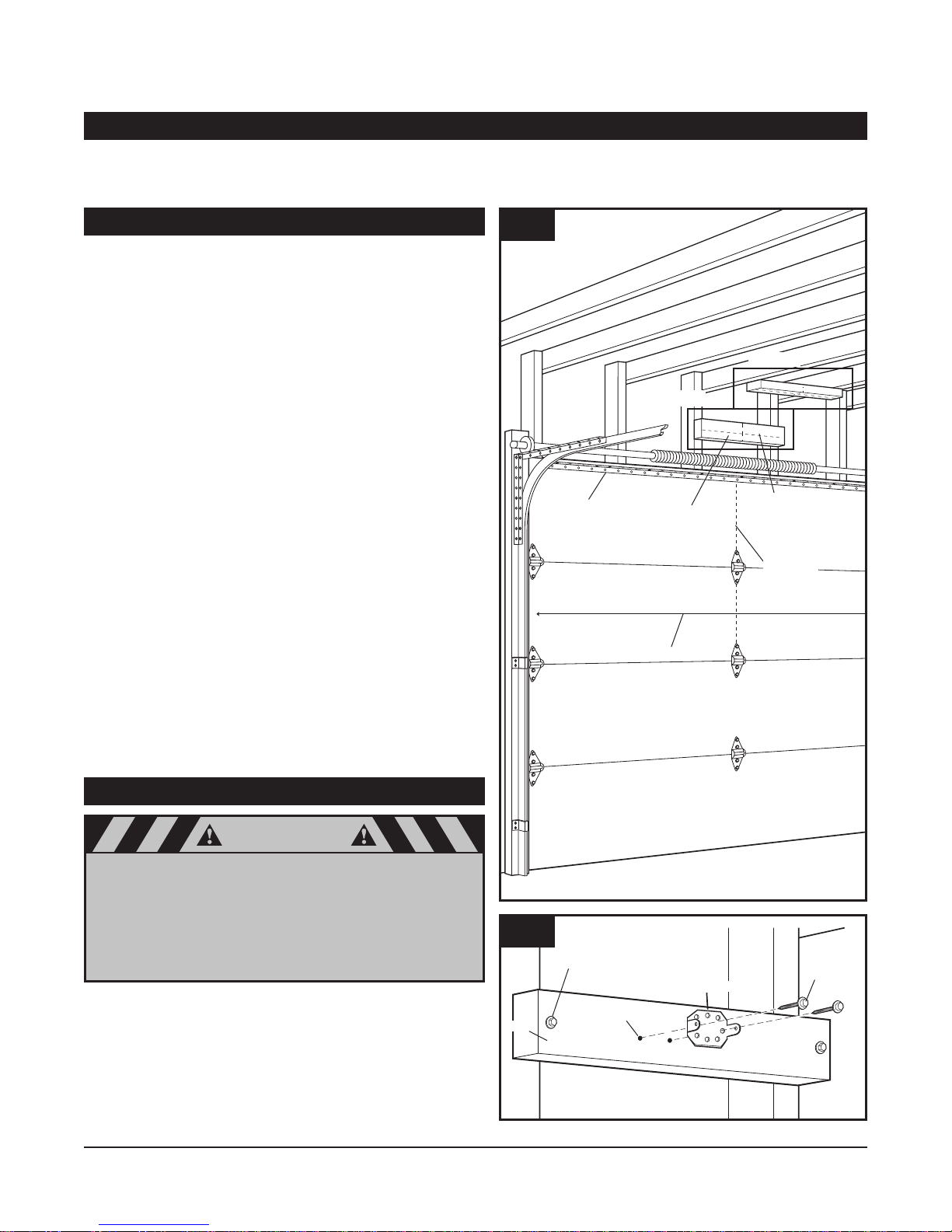
8.1 MEASURE AND MARK DOOR AREA .................................................................................................................................................................................. 8
8.2 INSTA HEADER BRACKET .................................................................................................................................................................................................... 8
8.3 INSTA DOOR BRACKET TO DOOR.................................................................................................................................................................................... 9
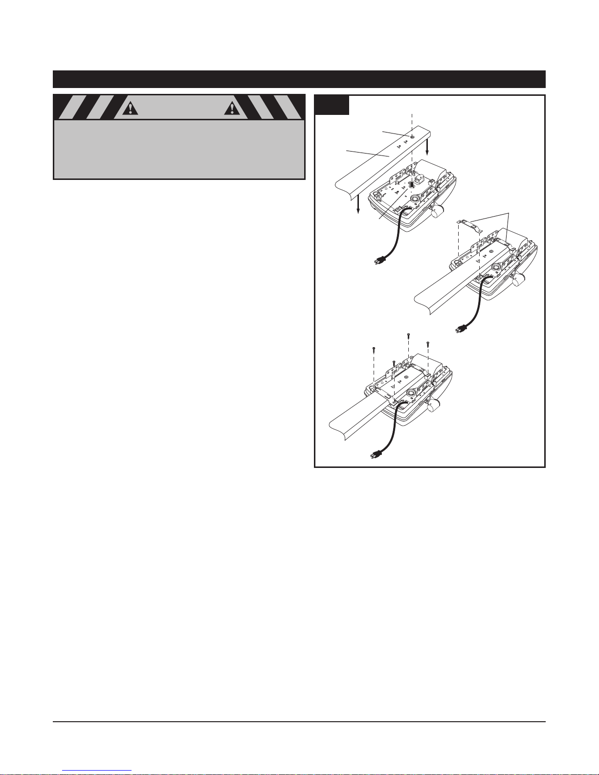
8.4 ATTACH RAI TO OPERATOR HEAD .................................................................................................................................................................................. 10
8.5 ATTACH RAI TO HEADER BRACKET ................................................................................................................................................................................ 11
8.6 POSITION OPERATOR FOR MOUNTING .......................................................................................................................................................................... 11
8.7 MOUNT OPERATOR TO CEI ING ........................................................................................................................................................................................ 12
8.8 CONNECT ARM TO DOOR AND TRO EY .................................................................................................................................................................... 12
8.9 CHECK EMERGENCY RE EASE .......................................................................................................................................................................................... 13
8.10 INSTA PHOTO EYE SAFETY SYSTEM ............................................................................................................................................................................ 14
8.11 INSTA WA CONTRO PANE ...................................................................................................................................................................................... 15
8.12 CONNECTING WIRES TO OPERATOR................................................................................................................................................................................ 15
8.13 INSTA IGHT BU BS AND ENSES .............................................................................................................................................................................. 16
8.14 CONNECT TO POWER .............................................................................................................................................................................................................. 17
8.15 CONTRO PANE ...................................................................................................................................................................................................................... 18
8.16 INITIA SYSTEM SET UP.......................................................................................................................................................................................................... 18
8.17 ADVANCED SETTING................................................................................................................................................................................................................ 20
8.18 TEST SAFETY REVERSA ..........................................................................................................................................................................................................23
8.19 A IGN AND TEST PHOTO EYE SENSORS........................................................................................................................................................................ 24
8.20 APP Y ABE S TO INSIDE OF GARAGE .......................................................................................................................................................................... 25
8.21 ATTACH OWNER’S MANUA TO WA ............................................................................................................................................................................ 25
9. IMPORTANT SAFETY INSTRUCTIONS........................................................................................................................................................................................................ 25
10. TRANSMITTERS .................................................................................................................................................................................................................................................. 26
11. OPERATION OF YOUR OPERATOR .............................................................................................................................................................................................................. 27
12. HOME INK®TRANSCEIVER .......................................................................................................................................................................................................................... 27
13. MODU AR ANTENNA ...................................................................................................................................................................................................................................... 27
14. TENSION ADJUSTMENT .................................................................................................................................................................................................................................. 28
15. RAI ENGTH ADJUSTMENT - FOR PROFESSIONA INSTA ERS ON Y................................................................................................................................ 28
16. RAI ASSEMB Y PARTS .................................................................................................................................................................................................................................. 29
17. OPERATOR ASSEMB Y PARTS ...................................................................................................................................................................................................................... 30
18. ACCESSORIES ...................................................................................................................................................................................................................................................... 32
19. HAVING A PROB EM? ...................................................................................................................................................................................................................................... 33
20. TROUB ESHOOTING - FOR PROFESSIONA INSTA ERS ON Y................................................................................................................................................ 34
21. MAINTENANCE AND ADJUSTMENTS ...................................................................................................................................................................................................... 35
22. IMITED PARTS WARRANTY.......................................................................................................................................................................................................................... 35
23. WARRANTY IMITATIONS, C AIMS AND SERVICE............................................................................................................................................................................ 36
24. REGISTRATION .................................................................................................................................................................................................................................................... 36
OWNER’S MANUAL CONTENTS
Conversion :
1 foot = 33 cm
1 inch = 2.54 cm

3
Warning
Operate the garage door operator at 120V, 60Hz to avoid operator damage.
Garage doors are heavy, moving objects. When coupled with an automatic operator, electrical power is
also present. f not properly installed, balanced, operated, and maintained, an automatic door can become
dangerous and cause serious injury or death. Please pay close attention to the WARN NG and CAUT ON
notices that appear throughout this manual. Failure to follow certain instructions may result in damage to
the door or door opener, or may result in severe injury or death to yourself or others.
Warning
CAUTION
WARN NG means that severe injury or death could
result from failure to follow instructions.
1. NTRODUCT ON
2. ADVANCED FEATURES
3. MPORTANT SAFETY NFORMAT ON
Congratulations on purchasing your GARAGA Professional Series Garage oor Operator System (G O), the most innovative operator available
today. This stylishly designed digital operator with a wide range of accessories is engineered to provide the smoothest, quietest and safest
operation to compliment any home. Advanced technology results in the operator being capable of easily moving almost any properly balanced
residential garage door, and at the same time providing state-of-the-art safety features to detect obstructions and to stop and reverse the door,
thus helping to protect persons and property near the door.
This operator includes numerous state-of-the-art features to provide you, the user, with years of trouble-free, convenient, and safe
use of your automatic garage door operator.
• Advanced Digital Operating System EOS (Easy Operating System): The EOS digital system provides a user friendly system set up.
The system set up comprises of two programing levels, a “Basic Level” and a “Advanced Level”. The EOS system requires only the basic set up
parameters. All other operating parameters are learned and set automatically by the system. In addition, the system optimizes all parameters with
every cycle for a more efficient operation by the G O. This shorter parameter set up provides a quicker and more efficient installation.
• Precision Controlled DC Motor, Complete with Automatic Soft Start and Soft Stop Feature: The operator automatically detects
when your door is almost fully closed or fully opened, and gradually slows the door down before it reaches its fully closed or opened position.
uring start-up, the door starts moving slowly and gradually ramps up to full speed for the full travel of your door. This reduces the possible
damaging effects of the sudden starts and stops associated with some other operators, and results in the smooth operation and increased
service life of your door and hardward.
• Built- n Safety Features: Including patented drive system that delivers only the optimum power needed to move your door safely - Every time!
• Modular Antenna Concept (patented): Plug-in your choice of frequency module.
• Photo Eye ( nfrared) Safety System: State-of-the-art infrared beam system helps detect obstructions in the path of your door and
automatically reverses closing door travel, helping to protect persons and property near the door.
• Convenient Status Display: To indicate the status of your door operator at any time. Especially useful if troubleshooting is necessary.
• Quiet Smooth Operation: Precision engineering and carefully selected materials result in extremely smooth and quiet operation, unmatched
by conventional garage door operators.
This manual is essential to the safe and proper installation, operation, and maintenance of your operator. Read and follow all guidelines and
operating instructions before the first use of this product. Store the manual in a safe, easily accessible location.
CAUT ON means that property damage or injury
could result from failure to follow instructions.

4
Pencil Tape Measure Drill and Drill Bits Adjustable Wrench
Wire Cutters Ratchet and Sockets
(1/2”, 7/16”)
Phillips Screwdriver Flat-Tip Screwdriver 7/16” Wrench
Stepladder
Fig. 1
Warning
Sectional Door
Fig. 2
CAUTION
4. TOOLS
The instructions will refer to the tools shown below for proper installation, adjustment, and maintenance of the garage door operator. Additional
tools may be required depending on your particular installation.
5. GARAGE
Take a moment to survey your garage and garage door.
• Is there an access door besides the garage door? If not, you should
install an emergency key release kit.
• With the garage door closed, check alignment of door and garage floor.
The gap, if any, should be no more than 1/4”. If the gap is larger than
this, repair floor or door before installing operator.
• The operator is intended for installation on a properly balanced and
adjusted garage door. O NOT INSTALL IF OOR IS UNBALANCE
OR BROKEN.
• Check balance of door in mid travel and during full range of opening and
closing. Lift the door about half way, (see Fig. 2). Release the door.
It should remain in place, supported by its springs. Raise and lower the
door fully to check for binding or sticking.
• If door is out of balance or needs repair, O NOT A JUST IT
YOURSELF. CALL A QUALIFIE GARAGE OOR SERVICE
PROFESSIONAL to adjust your door.
• If your door is over 7 ft. high, you will need a longer rail (see Fig. 7 on
page 6) “Rail Assembly” of this manual for availability of longer rails.
A garage door is a heavy moving object and can cause
serious injury or death. An unbalanced door might not
reverse when required, and can increase the risk of
injury. f your garage door is out of balance, or if it binds
or sticks, call for professional garage door service.
Garage doors, springs, pulleys, cables, and hardware
are under extreme tension and can cause serious injury
or death. Do not try to adjust them yourself. Ropes left
on a garage door could cause someone to become
entangled and could kill them. Remove all ropes
connected to the door before installing your operator.
To prevent damage to steel, aluminum, fiberglass
or glass panel doors, always reinforce the inside of
the door both vertically and horizontally with steel
or angle iron bracing.
The best solution is to follow the instructions for your particular garage
door or contact the garage door manufacturer for proper reinforce-
ment instructions.

8 1/2”
One Light Operator
Two Light Operator
10’ 10 1/4”
18 1/4”
10’ 6 1/2”
14 1/2”
1/2” 1 3/8”
14 5/8”
Headroom Clearance - 1 1/4”
12345678910
12345678910
1/2”
5
Header Wall
Header Bracket
Highest Point of
Door
Distance
Door Travel 1-1/4” Clearance
Sectional Door
with Curved Track
Fig. 3
Fig. 4
5. GARAGE (cont’d)
Check the type of door construction you have. The information contained in the figures below will be referred to later in the manual for proper
installation on the different door types.
GARAGE DOOR OPERATOR SYSTEM OVERALL D MENS ONS (7’ DOOR)

6
CarGO 700e
(Two Light
Operator)
CarGO 500e
(One Light
Operator)
Fig. 5
2-Channel Mini Transmitter
Transmitter Visor Clip
Cover
Programming
Connector
Garage Door Operator Manual and
Safety Labels
Wall Control Panel
(with Hardware Kit)
Photo Eye Safety System
Lag Screw (2): 5/16” x 1 3/4”
Curved Door Arm
Plastite Screw (4): 6 x 14
Clevis Pin (1): 5/16” x 7/8”
Cotter Ring (1)
Carriage Bolt (2): 1/4” - 20 x 2”
Lock Washer (2): 1/4”
Hex Nut (2): 1/4” - 20
Hex Bolt (2): 5/16” - 18 x 3/4”
Lock Nut (2): 5/16” - 18
Clevis Pin(1): 1/4” x 3 1/4”
Cotter Ring (1)
Hex Head Tek Screw (2): 1/4 x 3/4”
Lag Screw (4): 1/4” x 1 1/2”
Drywall Anchors (2) Staples (10)
30 ft. 2 Conductor Wire
Tapered-Head Screws (2)
Screw Caps (2)
Machine screws
(2)
Header Bracket
Door Bracket
Warranty
Card
Rail Clip (2)
Owner’s
Manuel
Warning
Operating
Warning
Label
Garage Door
Safety Label
Support Bracket
Fig. 6
Power Head
Accessories
Models (per application)
Belt Chain
7’ Door ML-807B ML-807C
7’ Door ML-808B ML-808C
7’ Door ML-810B ML-810C
Fig. 7 Rail assembly
(packaged in separate carton)
6. OPERATOR PACKAGE CONTENTS
The following items are included with your Garage oor Operator. All hardware components are located in the G O carton. The accessories are
packaged with their respective hardware in separate packs for ease of identification and use.
Hardware Kit
Items shown not actual size.

7
warning
MPORTANT NSTALLAT ON NSTRUCT ONS
TO REDUCE THE R SK OF SEVERE NJURY OR DEATH:
1. READ AND FOLLOW ALL NSTALLAT ON NSTRUCT ONS.
2. Check with the door manufacturer to determine if additional reinforcement is required to support the
door prior to installation of the garage door operator.
3. Install garage door operator only on a properly balanced garage door. An improperly balanced door
could cause serious injury. Have a qualified service person make repairs to garage door cables, spring
assemblies, and other hardware before installing the opener.
4. Remove all ropes and disable all locks connected to the garage door before installing operator.
5. If possible, install the door operator 7 feet or more above the floor. Adjust the emergency release cord so
that knob hangs 6 feet above the floor.
6. Do not connect the operator to source of power until this manual instructs you to do so.
7. ocate the wall control panel: (a) within sight of door, (b) at a minimum height of 5 feet above the ground
so small children cannot reach it, and (c) away from all moving parts of the door.
8. Place the Operating Warning abel next to the wall control panel in a prominent location. Affix Safety
abel on inside of garage door. The Emergency Release Tag must remain on the emergency release cord.
9. After installing the operator, test Safety Reversal System. Door MUST reverse when it contacts a 1-1/2
inch high object (or a 2x4 laid flat) on the floor.
For Important Safety Instructions see page 25.
Operating
Warning
Label
Owner’s
Manuel
Garage Door
Safety Label
Tag
Fig. 8
7. MPORTANT NSTALLAT ON NSTRUCT ONS
Shown on the right is an overall view of a
completed garage door operator system
installed on a sectional door. The arrange-
ment is similar for a one-piece door (except
for differences described later in this manual).

8
Horizontal
Reinforcement
Bracket
Header
Horizontal Line
for Header Bracket
Height
Door Width
See Fig. 11
See Fig. 10
Vertical
Center Line
Fig. 9
Header
Lag Screw for Header installation
if necessary (not provided)
Header Bracket
Lag Screw
5/16” x 1 5/8”
Pilot hole
Fig. 10
Warning
f the header bracket is not rigidly fastened to a sound
structural support on the header wall or ceiling, the
safety reverse system may not work and could cause
serious injury or death. DO NOT move or adjust springs
or garage door hardware, as these parts are under
extreme tension and could cause injury or death.
8. NSTALLAT ON STEPS
Identify a sound structural support on header wall above garage door for header bracket mounting (see Fig. 10). If appropriate header does not
exist, replace or install a new support using a 2x4 or 2x6 board. Fasten it securely using lag screws (not provided) to structural supports of garage.
8-1. MEASURE AND MARK DOOR AREA
Before starting your installation, the door and the header above the door
must be measured and marked. This way, the appropriate brackets can be
mounted at the correct locations avoiding installation and operating
difficulties later.
MARK VERT CAL CENTER L NE:
• Measure door width, then locate the center point (see Fig. 9).
• Mark a vertical line on the upper half of your door, on the top edge of your
door, and on the header, through the center point.
MEASURE DOOR’S H GHEST TRAVEL PO NT:
(Review Figs. on p. 5 for details)
• Open door to its highest travel point and measure from the garage floor
to the top of door.
• Write down this distance.
• Add 1-1/4” to the door travel height (measured above).
MARK HOR ZONTAL L NE FOR HEADER BRACKET LOCAT ON:
• Close door and measure the required distance (determined above) from
the garage floor to the header.
• Mark a horizontal line, intersecting the vertical center line, on header.
This is the position at which the bottom of the header bracket should
be installed.
• In case of minimal clearance above the door, the header bracket may be
mounted to the ceiling. In this case, extend the vertical center line onto
the ceiling, and mark a horizontalline on the ceiling no further than 4”
from the header wall. The header bracket should be mounted no farther
than this distance from the header wall.
8-2. NSTALL HEADER BRACKET

9
8-2. NSTALL HEADER BRACKET (cont’d)
• Mark pilot holes location on header through header bracket holes where
lag screws will be inserted. MPORTANT: See Fig. 10 for which header
bracket holes to use.
•rill 3/16” pilot holes into header, and install bracket with lag screws
(5/16 x 1-3/4”) provided.
• Tighten lag screws firmly.
NOTE: Follow the same procedure if header (see in Fig. 10) runs vertically
instead of horizontally and is the only option for mounting header bracket
to header wall. In case of minimal clearance above the garage door, the
header bracket may be mounted to the ceiling. Follow the same steps
above to ensure a sound surface for mounting.
Ceiling
Header
Bracket
Lag Screw
Pilot Hole
Fig. 11
8-3. NSTALL DOOR BRACKET TO DOOR
Wood Sectional Doors (Fig. 13)
• Position door bracket (see Fig. 12) along vertical center line of door with
pin hole facing top of the door and top edge of the bracket 4” to 5”
below top edge of the door, or roughly at the same height as top rollers
on the door.
• Mark locations of securement holes through door bracket.
• rill two 1/4” holes through door for securement of door bracket.
• Insert carriage bolts (1/4” x 2”) from the outside through door and
bracket, then secure with lock washers and nuts from the inside.
• Tighten nuts firmly.
Metal Sectional Doors
• Attach door bracket with two teck screws (provided) per oor
manufacturer recommendations.
Pin Hole
Fig. 12
Insert 1/4-20 X 2”
Carriage Bolts
from outside of door
Lock Washer
1/4-20 Nut
Wood Sectional
Doors
Door Bracket
Fig. 13

10
Warning
8.4 ATTACH RA L TO OPERATOR HEAD
B. Position “C” Rail Clip
over rail
A. Place Rail onto Chassis
Sprocket
Opening
Rail
Motor Head Shaft
“C” Rail Clip
C. Secure “C” Rail Clip to Chassis
6x14 Screw
Fig. 14
NOTE: Rail comes fully preassembled with straight door arm already
attached.
• Unpack one-piece preassembled rail.
• Leave straight door arm taped inside rail for safe and convenient
installation—it will be untaped and used later.
• Position operator with control panel facing front of garage. Rest operator
head on cardboard or protective surface on floor so opener does not get
scratched. Chassis side of opener (with motor shaft sticking out)
facing up.
• Position rail onto operator chassis by lining up rail sprocket opening with
motor head shaft (see Fig. 14A). Make sure shaft engages teeth inside
rail sprocket. Press rail down firmly onto shaft and opener chassis. O
NOT HAMMER.
• Position 2 “C” rail clips over rail and onto chassis. Flanges on “C” rail clips
MUST fit into guide posts recesses (see Fig. 14B).
• Insert screws (6 x 14) through bracket holes and into chassis holes, and
tighten screws firmly to hold rail to head (see Fig. 14C).
When fastening the rail to the operator, use only the
screws provided. Use of any other screws may result
in operator falling from ceiling and causing damage
to persons or property in the garage.

11
Operator Box
Fig. 15
Header Bracket
Rail End-Stop
Cotter Ring
1/4 x 3/14”
Clevis Pin
Rail
Fig. 15A
Door 2 x 4 Laid Flat
Stepladder
Fig. 16
8-5. ATTACH RA L TO HEADER BRACKET
Support operator head slightly off the floor.
Lift the opposite end of the rail up to the header bracket.
Position rail end-stop within the openings in the header bracket. Insert
header clevis pin (1/4” dia.) through header bracket and rail end-stop, then
attach cotter ring to end of pin (see Fig. 19A).
8-6. POS T ON OPERATOR FOR MOUNT NG
Once rail is attached to header bracket, support operator power head on
ladder, or use the assistance of another person to support operator high
enough so door can open without hitting the rail.
• Open garage door to fully opened position, and place a 2x4 laid flat
between the door and the rail (see Fig.16).
• The 2x4 provides an easy method of ensuring the correct mounting height
of the opener.

12
8-7. MOUNT OPERATOR TO CE L NG
8-8. CONNECT ARM TO DOOR AND TROLLEY
12345
6789
1
0
Fig. 17
warning
f not properly secured, the operator could fall and
injure someone. Secure opener to structural supports
or framing. Do not mount to drywall, plaster, or other
such material.
• Position operator head so that rail is lined up with center line of
open door.
• Line up hanger brackets (not provided) with ceiling joists or framing to
locate where brackets are to be fastened (see Fig. 17)
• Mark location for 5/16” lag screws (not provided), and drill two
3/16” pilot holes.
• Fasten hanger brackets to joists using lag screws.
• If garage framing supports are not visible, attach a length of perforated
angle or a 2x4 to the ceiling, securing it to the hidden joists with lag
screws long enough to fasten firmly to garage framing (extra hardware
items not provided). Then, attach one end of hanger brackets to the angle
or 2x4 mounted to ceiling. Attach other end of hanger brackets to
operator’s perforated angles (see Fig. 18) for an alternate mounting methods.
• Once operator is securely fastened in position, remove wood blocks and
temporary supports and lower door. Check door for proper operation and
clearance by manually moving door to full open and closed position. If
door hits rail at any point, raise operator head slightly higher and
re-mount in position.
NOTE: To provide additional support for 10 ft. Doors and higher, use the
optional support bracket. (Accessories p.28)
• Measure the rail’s overall span. Bracket is located on 1/3rd of the overall
rail span from the door header bracket end (see Fig. 19)
• Place support bracket over rail (close side) on a diagonal. Make sure
support securement clamps clear rail sides.
• Secure bracket onto rail by twisting support bracket as indicated in (see
Fig. 19A).
• Attach mounting strap (not provided) to support bracket and secure by
fastening it to the ceiling.
Joists (may be hidden
behind drywall)
Perforated angle
123
4
5
6
7
8
9
1
0
Fig. 18
Support Bracket
1/3 (S)
1st “C”
Rail Clip
Rail Span (S)
Fig. 19
Rail
Support d’appui
Fig. 19A
Angle
Fig. 20
• Make sure door is fully closed.
• Remove tape from rail holding straight door arm (sectional door only) and
allow door arm to hang freely.
• Pull the manual release cord on the trolley to disconnect trolley from chain
or belt connector. Slide trolley to position it about 4” away from the door.

13
8-8. CONNECT ARM TO DOOR AND TROLLEY (cont’d)
Warning
5/16”-18 x 3/4” Hex Bolt
5/16”-18
Lock Nut
5/16”x7/8” Clevis Pin
Cotter Ring
Curved Door Arm
Straight Door Arm
Fig. 20A
Rail
The release cord and knob should be adjusted
to hang 6 ft. above garage floor.
To adjust:
- Slide knob and tag up on cord.
- Tie new knot at correct height.
- Cut excess cord, leaving approximately 1” after knot.
- Heatseal end of cord with match or lighter to
prevent fraying.
- Slide knob and tag back into place.
- Check operation of emergency release.
PULL DOWN
Red Emergency
Release Knob
Emergency Release Cord
Fig. 21
Unlock
Latch
Lock
Red Catch
Indicator Window
Fig. 21A
• Position curved door arm into door bracket channel so that short end of
arm will be attached to door bracket (see Fig. 20A). Curved door arm
should be attached roughly at the same height as the top rollers of
the door.
• Align curved door arm and bracket holes, then insert clevis pin through
holes. Attach cotter ring to hold pin in place.
• Position straight arm and curved arm to form an angle with the door
(see Fig. 20) and at least two sets of holes line up. Select two
overlapping holes as far apart as possible and secure arms together with
hex bolts (5/16-18) and lock nuts.
• After connecting appropriate door arm, ensure trolley is disengaged.
Check for proper door operation by manually lifting then lowering to fully
opened and closed positions.
• Readjust door arm if needed.
PULL DOWN ON RELEASE KNOB TO LOCK TROLLEY, THEN
MOVE DOOR MANUALLY UNT L TROLLEY LOCKS W TH CHA N
OR BELT CONNECTOR.
8-9. CHECK EMERGENCY RELEASE
The emergency release cord with red knob, which is already attached to the
trolley, are extremely important parts of the operator system (see Fig. 21).
Pulling the release cord disengages the door from the opener. This allows
the door to be moved manually up and down independent of the opener motor.
f the door is in the open position, use extreme care when using
the release.
Use emergency release to disconnect the door if the power is out. It should
also be used if for some unforeseen reason the door strikes a person or
object during its travel and does not automatically reverse off the obstruction.
To release door - pull firmly down on red knob. (Fig. 21)
Prior to re-engaging door, ensure that all obstructions are removed and
door is operating properly manually. Before re-engaging trolley with a chain
or belt connector, pull down knob again, then release. The red catch will
stop in the “lock” position and will open indicator window (see Fig. 21A).
Now the door can be reconnected by moving it manually and bringing it
into position when the connector is inside of the trolley.
Use extreme care when pulling release knob. DO
NOT use knob to pull door open or closed. Except
for emergency situations, use knob only when door
is closed.

14
8-10. NSTALL PHOTO EYE SAFETY SYSTEM
Cover Flap with
Terminal Marking
1
2
TX
Receiver (RX) or
Transmitter (TX)
Mark
Indicator Light
Lens
Fastening Wheel
T
erminal Holes
Wiring to Powerhead
T
o Terminal 1
To Terminal 2
Tabs
Sensor Cap
Sensor Cap Fastener
1
2
2
1
Fastening Wheel
Photo Eye Sensor
Wire terminal must point
downward towards
garage floor
Fig. 22
To provide the maximum amount of protection, the photo eye sensors
must be mounted between 3” and 4-1/2” above the floor (see Fig. 23).
Wall Stud
Mounting
Bracket
Lag Screws (2)
Wall
3” to 4-1/2”
from floor
3” to 4-1/2”
from floor
Fig. 23
Receiver
Transmitter Transmitter Receiver
Fig. 24
CONNECT NG W RES TO THE PHOTO EYE SENSORS:
(if required). Fig. 22
• Open the black cover flap.
• Insert stripped end of wires into terminal holes by pushing directly into
hole (white wire in terminal #1 and wire with stripes into terminal #2).
• After inserting the wire in the proper terminal, pull on the wire to ensure
proper connection has been made. If the wire pulls out repeat the
above steps.
• Place the wires in the slot from the right side of the cover and close cover.
MOUNT NG THE PHOTO EYE SENSORS TO BRACKET:
(if required). Fig. 22
• Attach the sensor cap and the sensor cap fastener to the bracket.
• Secure the photo eye sensor to the bracket with fastening wheel.
• Repeat process for the other sensor.
MOUNT NG THE PHOTO EYE SENSOR BRACKETS TO WALL:
• Locate the mounting position for brackets (bracket can be mounted in any
position as long as photo eye beam will have a clear path from one side
of door to the other side after mounting).
• Use the bracket mounting holes as a template to locate and drill (2) 3/16”
diameter pilot holes on both sides of the garage door 3” to 4-1/2” above
the floor.
• Secure the bracket assemblies with 1/4” x 1-1/2” lag screws (see Fig. 23).
• Align photo eye sensors, so they face each other.
MOUNT NG THE PHOTO EYE SENSORS D RECTLY TO WALL
(optional):
• Locate the installation position (see Fig. 23).
• Remove sensors from brackets.
• Use the photo eye sensor mounting holes as a template to locate and
drill two 1/6” pilot holes into wall (if mounting to drywall instead of wood,
drill two 3/16” pilot holes).
• Secure the photo eye sensor assemblies with #6 screws and anchors
(not provided).
• Repeat process for the other photo eye sensor.
DUAL DOOR NSTALLAT ON:
• In dual door installations, the transmitter (TX) and the receiver (RX) photo
eye sensors (as marked on each of the photo eye components) should
be mounted (see Fig. 24).
• TX and RX marks located on the top side of the PCB, near the terminal
area (see Fig. 22).

15
8-11. NSTALL WALL CONTROL PANEL
4
3
T
o Terminal #4 Screw
T
o Terminal #3 Screw
Screw caps
Fig. 25
The control panel must be mounted inside the garage within sight of the
garage door, clear of all moving garage door parts or any associated parts
- and at least 5 feet above the floor to prevent the use of these controls by
children. The device should only be used when the door is in clear sight of
the user and the door area is free of people or any obstructions.
• Attach 2-conductor wire to the screw terminal on back of control panel
(see Fig. 25 (Back)). White wire attaches to terminal #3 screw, white
wire with color stripes attaches to terminal #4 screw.
• Position wall control panel onto wall in desired location.
• Mark hole location on wall.
• rill 1/16” pilot holes into wall.
• Insert and tighten screws to secure control panel to wall.
• Make sure wiring is routed out from behind control through one of the
cutouts to avoid pinching the wires.
If mounting to drywall instead of wood, drill 3/16” pilot holes and use
anchors provided.
If mounting to electrical box that is prewired for this purpose, mount
directly to box with proper screws provided .
24V
Common (Ground)
Relay
T
R
Wall Control
Photo Eye
Fig. 26
To Terminal 1
To Terminal 2
To Terminal 4
To Terminal 3
Fig. 26A
8-12. CONNECT NG W RES TO OPERATOR
• Run wires from wall control panel and photo eye system along wall and
ceiling to operator powerhead. Use the staples to secure wiring to wall,
joists and ceiling. o not pinch wiring. rive staples with only enough
force to hold wiring in place. Refer to Fig. 8 on p.7 for an example of
typical wiring routing, and Fig. 26 for terminal assignment.
NOTE: As an alternative for photo eye system, the wiring can be routed
along the top of the rail, or along the outside of the door track. Be sure the
wiring is routed away from all moving parts of the door and rail.
• Separate 2” of double wire from each photo eye sensor into two single
wires. Strip about 1/2” of insulation from the end of each of the four
single wires. Combine the white wires from each sensor and twist
stripped ends together tightly. o the same with color striped wires.
• Open the control panel by slightly pulling on the panel cover tabs.
• Feed wall control and photo eye system wires through wire guide from the
top of the chassis into terminal area of control panel.
• Firmly insert white wire combination into terminal hole #1 by pushing
directly into hole. Insert color striped wire combination into terminal #2.
NOTE: If wires are difficult to insert, a screwdriver may be used to depress
the terminal “tab” while inserting the wires. To remove wires, depress tab
again and pull wires out.
• Insert white single wire from wall control into terminal #3 and single color
striped wire into terminal #4.
NOTE: Multiple wall controls may be installed in parallel with wires
connected to terminals #3 and #4.
• etach right side panel from one of the wall controls (see Fig.25).
• Attach wiring to back of both wall controls (White wires to terminal #3
screws, wires with stripes to terminal #4 screws.)
• Follow the same steps as above to mount additional wall control panels
and wire connections.

16
CAUTION
8-13. NSTALL L GHT BULBS AND LENSES
• Install a maximum 60 W incandescent bulb (not provided) into lamp
socket(s).
•Install lamp lens(es). Two lenses for a CarGo 700e model (see Fig.
27A). Lenses are not interchangeable, the design is left / right
orientation dependent. One lens for a CarGo 500e model.
•Line up lamp lens tabs with slots in housing and snap securely into
place. Repeat same procedure with second lamp lens on the
opposite side, if you have an CarGo 700e power head.
• Line up lamp lens tabs with corresponding slots in chassis. Snap
lens onto chassis for CarGo 500e model.
• To remove lamp lens, pull lamp lens to unsnap from housing
and chassis.
Hinge lamp lens downward
line up tabs with slots in housing
and snap into place.
Snap lamp lens tabs
into slots in chassis
Install Bulb
CarGO 700e
CarGO 500e
Housing Slots
Chassis Slots
Lens Tabs (housing)
Lens Tabs (chassis)
Chassis Slots
Housing
Slots
Install Bulb Snap lamp lens tabs
into slots in chassis Hinge lamp lens downward
line up tabs with slots in housing
and snap into place.
Standard incandescent
light bulb 60W (max.)
Lens Tabs (chassis)
Standard incandescent
light bulb 60W (max.)
Fig. 27
Warning
To prevent possible serious injury and damage to
the operator when replacing the light bulbs:
Disconnect ALL electric and battery power BEFORE
performing ANY service or maintenance.
NOTE: se only standard light bulbs. The use of short neck or specialty light bulbs may overheat the endpanel or light socket.
Left lens
80349
Right lens
80348
Fig. 27A
To prevent possible OVERHEAT NG of the end panel or
light socket:
• Use ONLY standard incandescent light bulb(s).
• DO NOT use a bulb with a rating higher than 60 Watts (W).
A stronger or larger bulb may result in fire or damage to the
opener.
To prevent possible radio frequency (RF) signal
interference:
• Do not use compact florescence lighting (CFL).

17
8-14. CONNECT TO POWER
To reduce the risk of electric shock, your opener is provided with an
insulated power cord with a 3-prong grounding plug. The cord must be
connected to a standard grounding outlet. If there is no outlet available at
the location, you must have a qualified electrician install an approved
grounded outlet in this area.
Grounded Outlet
Power Cord
Fig. 28
Wires: (remaining 6”)
Ground (Green)
Hot (Black)
Neutral (White)
Strain relief
Fig. 29
Nylon cable tie
Fig. 29A
• Plug the operator into a properly grounded outlet (see Fig.28).
• An indicator lights (LE ’s #4 and #8) on the operator control panel will
turn on showing that the power is “On” and the opener is ready to set
the adjustments.
• O NOT operate or run the opener at this time.
PERMANENT W R NG CONNECT ON:
(If required by your local electrical code)
If local codes require your operator to be connected via permanent wiring
instead of a cord and plug, your operator must be converted, (see Fig. 29).
Contact a qualified electrician to run the necessary wiring to your
operator and to perform the electrical connections.
• Remove operator housing by removing the four screws, two screws
located at the front by the control panel area, and two screws located on
the back of the unit, then pulling the housing away from the chassis.
• Cut the power cord close to strain relief cover, so that after cut, there is
at least 6” of wiring remaining. Remove approx. 1 ½” of black insulation
left on the cable to expose the three conductor leads (white-neutral,
black-hot, and green-ground).
• Remove screw and unsnap the power cord strain relief cover by
disengaging the tabs, and remove this part (save for reattachment later).
• Remove the cut power cord and discard. Replace the strain relief cover
by snapping tabs back into place.
• Using a hammer and screwdriver or punch, knock out conduit hole, and
bring in the permanent wiring and conduit.
• Secure conduit to chassis (method varies depending on type of conduit used).
• Attach the incoming power leads (hot, neutral, and ground) to the
remaining internal wires using suitable wire nuts (not provided). Tight
wire leads together with a nylon cable tie to avoid the leads from coming
in contact with the relay circuit board, (see Fig. 35A).
• Reinstall operator housing and secure housing with screws. Make sure
that when reinstalling operator housing, no wires will be pinched between
the housing and the chassis.
• Complete the remaining installation.
• Turn on power at breaker.
Warning
To prevent electrocution, disconnect the operator from
power and turn off power at circuit breaker for the
circuit you will be using to connect to the opener.
Warning
To prevent electrocution or fire, installation and wiring
must be done in accordance with local electrical and
building codes. DO NOT use an extension cord. DO NOT
use a 3 to 2 plug adapter. DO NOT modify or cut off the
grounding pin on the plug.

18
8-15. CONTROL PANEL
On the control panel (see Fig. 30) you will find circular LE display with 8
numbered icons which shows useful status information regarding the
perator and its function and 3 buttons labeled “+”, “-” and “P” which allows
you to set all the adjustments of your operator.
P
1
2
1
5
3
7
2
4
6
8
+
2
4
7
Fig. 30
Warning
n order to guarantee trouble-free programming, the
door must be in the CLOSED door position before
programming or system reset.
For proper initial operation of the operator, three basic functions must be
set using express programming:
• Open oor Position
• Close oor Position
• Transmitter Coding
Press and hold the “P” button for approximately 5 seconds. When LE ’s 8,
1 and 2 illuminate, release the button. You are now ready to set or change
the desired adjustment. If no buttons are pressed within 120 seconds while
in programming mode, the control unit reverts back to operating mode.
TO MAKE OR CHANGE ANY ADJUSTMENT:
HAN Y NOTE: If no changes are needed at any particular stage, you can
keep the current information and “skip” over a specific adjustment by
pressing the “P” button once. This is useful to know if you want to change
only one setting, without changing any of the other adjustments. Simply
enter the adjustment mode by pressing and holding the “P” button for
pproximately 5 seconds, then press and release “P” repeatedly until your
particular adjustment is reached. This bypasses the unneeded adjustments,
and takes you right to the adjustment you want. When your adjustment or
setting is complete, simply press ”P” as many times as needed to bypass
the remaining steps and exit out of the program, returning the operator to
normal mode.
Your new operator has automatic force learning and maximum force setting.
It may be required to change force settings. If the force needs to be
increased or decreased, it should be changed by one (1) increment at a
time. The force should be set as low as possible, just enough to allow your
unobstructed door to travel freely without reversing or stopping.
NOTE : You may exit the System Set p at any time by pressing the button
“P” for more then 5 sec. The set up programming can be terminated at any
time and from any stage. To do so, press the “P” button for longer than 5
seconds. When programming is terminated, all LED’s light up once and then
turn off, one after the other.
1
2
Fig. 31
8-16. N T AL SYSTEM SET UP
Key to icons and corresponding LED’S
Led 1 Photo eye sensors
Connectivity / Alignment indicator
Led 2 “OPEN door position”
Led 3 “No function during operation”
Led 4 “CLOSE door position”
Led 5 “Reference Point”
Led 6 “Malfunction”
Led 7 “Impulse (remote control)”
Led 8 “Power”

19
8-16. N T AL SYSTEM SET UP (cont’d)
Power on
1
P
1x >5s< 10s
Start initial system setup
by programming the door
OPEN position.
1
5
3
7
2
4
6
8
2
+
Bring the door to the desired
OPEN postion.
1
5
3
7
2
4
6
8
3
+-
Fine adjustment if necessary.
Adjust the OPEN door position
using (+) and (-).
1
5
3
7
2
4
6
8
1
5
3
7
2
4
6
8
4
P
1x <1s
Save the OPEN door position.
Start programming the
CLOSED door position.
1
5
3
7
2
4
6
8
5
-
Bring the door to the desired
CLOSE position.
1
5
3
7
2
4
6
8
6
+-
Fine adjustment if necessary.
Adjust the CLOSE door
position using (+) and (-).
1
5
3
7
2
4
6
8
1
5
3
7
2
4
6
8
7
P
1x <1s
Save the CLOSED door
position. Program the
transmitter code to GDO.
1
5
3
7
2
4
6
8
8Press the transmitter
button. LE #7 flashes rapidly.
1
5
3
7
2
4
6
8
9Release the transmitter button.
1
5
3
7
2
4
6
8
10
P
1x <1s
Save the transmitter code
settings. End the system setup
(programming) procedure.
1
5
3
7
2
4
6
81
5
3
7
2
4
6
8
Operating
mode
egend:
LE off
LE on
LE flashes slowly
LE pulses
LE flashes quickly
Factory default setting
Not possible -
Always remember to have the door travel 2 cycles to complete the
programmation cycle.
With any modification to the weight of the door, enter the programmation
mode and skip 3 steps, then have the door travel 2 cycles to set the forces.

20
8-17. ADVANCED SETT NGS
Advanced settings programming flow chart
(Diagram illustrates: Level 2, Menu 2)
CAUTION
ParameterMenuLevels
+
-
+
-
+
-
+
-
Level 3
> 10 sec.
+
-
+
-
+
-
Level 4
Level 2
+
-
Level 8
+
-
Levels Exit
P
P
> 5 sec.
P
Menu 1
Menu Exit
(Level 2)
+
-
Menu 2
+
-
Menu 3
+
-
Menu 8
Parameter
Increase
value
Reduce value
P
P
P
+
-
Level 1
+
-
+
-
+
-
+
-
> 5 sec.
P
> 5 sec.
P
(Continue to levels
5,6,7)
Levels 3, 4, 6, 7 are disable
P
P
Operating
mode
End
programming
Additional operator functions can be set using the
expanded operator functions. mportant factory
default settings can be changed there. This
rogramming may only be carried out by professional
installer.
This manual suits for next models
1
Table of contents
Other Garaga Garage Door Opener manuals
Popular Garage Door Opener manuals by other brands

Raynor
Raynor RapidCoil RC300 Series Technical manual

Chamberlain
Chamberlain 821LM quick start guide

Proteco
Proteco Aster 3 Installation and use manual

Genie
Genie SCREW DRIVE GARAGE DOOR installation instructions

Chamberlain
Chamberlain LiftMaster LM800A-2 Technical data

Chamberlain
Chamberlain 1200 owner's manual

BFT
BFT EOS 120 VENERED Installation and user manual

Chamberlain
Chamberlain H Replacement parts

BFT
BFT BOTTICELLI BT A 650 Installation and user manual

Motorisation+
Motorisation+ SIMPLY Instructions and warnings for installation and use

Raynor
Raynor 3595RGD 3/4 HP owner's manual

Assa Abloy
Assa Abloy Besam PowerSwing CSDB Installation and service manual