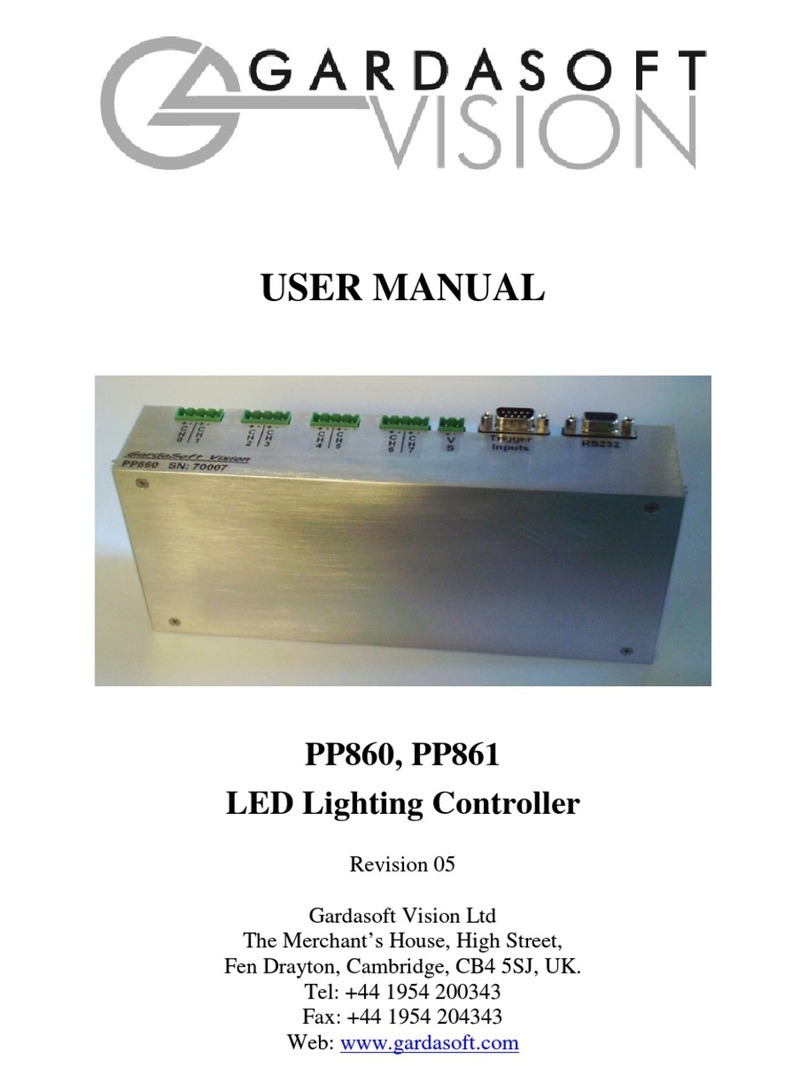
Gardasoft Vision PP600F User manual

USER MANUAL
PP600F, PP602F, PP610F, PP612F
LED Lighting Controllers
Revision 10
Gardasoft Vision Ltd
Trinity Court, Swavesey
Cambridge, CB24 4UQ, UK
Tel: +44 1954 234970
Fax: +44 1954 231567
Web: www.gardasoft.com

2

3
1Disclaimer
Except as prohibited by law:
All hardware, software and documentation is provided on an “as is” basis.
It is essential that the user ensures that the operation of the product is
suitable for their application.
The user must ensure that incorrect functioning of this equipment cannot
cause any dangerous situation or significant financial loss to occur.
Gardasoft Vision Ltd and Gardasoft Products Ltd will not accept any
liability for consequential loss of any kind.
All trademarks acknowledged.
Hardware, software and documentation are Copyright 2002 – 2003 Gardasoft
Products Ltd. Hardware manufactured by Gardasoft Vision Ltd under licence.

4
2Getting Started
Read the sections on Safety and Specifications and check the PP600F fulfils
your requirements. Gardasoft Vision also produce the PP101, an eight channel
current controller with computer control.
Connect the PP600F up to a supply and an LED lighting unit as described in
“Connections.” Note that the supply voltage must be connected to three
terminals. When the PP600F powers up it should show two alternating lines on
the display to indicate that it is operating properly.
Read the section on “Operation” and use the Simple Set Up to make the
PP600F supply a small continuous current to the LED unit. Check that the LED
unit illuminates.
Users who have a PP610F or PP612 should refer to the PP610F section and
read how to send RS232 commands.
Mount the PP600F as described in “Mechanical Fixing” using a DIN rail or the
mounting holes. In particular read the notes on heatsinking.
Set up the PP600F for the desired operation and test.
See the appendix on Application Notes for additional information on the use of
the PP600F. Visit www.gardasoft.com for more Application Notes.
Throughout this manual, references to the PP600 refer to all variants in the
PP600F range unless otherwise stated. The symbol “us” is used to denote
microseconds.
2.1 Differences From PP600 Range
Please note that the PP600F range has the following differences from the
PP600 range:
•Faster, more repeatable pulse widths
•Pulsing output channel 1 can only be triggered from INPUT1
•Pulsing output channel 2 can only be triggered from INPUT2
•Pulse widths and delays are a maximum of 9.9ms
•When setting up pulsing using the buttons, the output current is set before
the pulse delay.

5
3Safety - English
3.1.1 PP600 – Safety
Please read this before using the PP600 family of products. If in doubt, contact
your distributor or Gardasoft Vision.
Where this symbol appears in the manual, refer to the text for
precautions to be taken.
3.1.2 Heat
The PP600 can get very hot. It should be positioned where personnel
cannot accidentally touch it and away from flammable materials.
Do not exceed the power ratings given in the manual. Note that at the
maximum ratings the case temperature can reach 80oC.
If the output load is short circuited then the heat dissipated within the unit will
greatly increase, resulting in a further rise in temperature.
3.1.3 Electrical
The user must ensure that the potential difference between any combination of
applied signals does not exceed the supply voltage. WARNING: Higher
voltages may cause a danger to personal health.
The PP600 does not have complete tracking isolation of inputs and outputs.
Transients caused by inductive loads must be suppressed external to the PP600.
The metal case is not connected to PSU 0v. This is a change from previous
revisions of the PP600.
3.1.4 General
The PP600 must not be used in an application where its failure could cause a
danger to personal health or damage to other equipment.
If the equipment is used in a manner not specified by the manufacturer, the
protection provided by the equipment may be impaired.

6
4Safety - German
4.1.1 Sicherheitshinweis PP600
Bitte lesen Sie sich diesen Sicherheitshinweis gründlich durch, bevor
Sie die Produkte der Serie PP600 benutzen. Sollten dennoch Zweifel
Ihrerseits bestehen, zögern Sie nicht sich mit uns in Verbindung zu
setzen. Die Stellen im Handbuch, an denen dieses Symbol erscheint, beziehen
sich auf den Text zur Beachtung der Vorsichtsmaßnahmen.
4.1.2 Wärmeentwicklung
Die Geräte können während des Betriebes sehr heiss werden. Sie
sollten daher dort untergebracht sein, wo Personen keine
Brandverletzungen erleiden können und wo sich keine entflammbaren
Materialen befinden.
Überschreiten Sie nicht die im Manual angegeben Höchstspannungen.
Beachten Sie, dass die Temperaturen bei der maximalen Spannung 80 °C
betragen können.
Wird pro Kanal mit hohen Blitzspannungen und kurzen Blitzzeiten gearbeitet,
steigen die Temperaturen nochmals an!
4.1.3 Elektrischer Betrieb
Stellen Sie sicher, dass die Spannungsdifferenz bei keiner Kombination der
angelegten Signale die Versorgungsspannung übersteigt. ACHTUNG: Höhere
Spannungen können sich Gesundheitsgefährdend auswirken.
Ein- und Ausgänge haben keine komplette Leiterbahnisolierungen.
Überschläge, die aus Induktion resultieren können, müssen ausserhalb des
PP600 abgehalten werden.
Das Metallgehäuse ist nicht mit PSU 0V verbunden. Dies ist eine
Veränderung zu früheren Versionen des PP600!
4.1.4 Generell
Die Controller der PP600 Serie darf nicht in Applikationen eingesetzt werden,
in welchen ein Fehlverhalten des Gerätes gesundheitliche Schäden verursachen
könnte oder technische Ausrüstung zerstören könnte.
Wenn das Gerät auf nicht vom Hersteller spezifizierte Weise benutzt wird,
können seine Schutzvorrichtungen beeinträchtigt werden.

7
5General Description
The PP600 current controller provides repeatable intensity control of LED
lighting for machine vision applications. It includes the power supply, intensity
control, timing and triggering functions required for machine vision systems.
LED lighting needs a constant current supply as small variations in voltage can
cause large variations in light output. Currents can be specified in 0.25mA
steps below 1A and in 1mA steps above 1A.
Three modes of operation are provided separately for each channel:
Continuous:
In continuous mode the output is a continuous current.
Selected Continuous:
In selected continuous mode one or both inputs can be used to select an
output current. For each state of the inputs, the output current is fixed.
Strobed:
In this mode output is pulsed once per trigger. One input is used as a
trigger. The delay can range from 8us to 9.9ms in 1us steps. The pulse
width can range from 1us to 9.9ms in 1us steps.
The PP600 is set up using four push buttons and a four digit seven-segment
display.
Configurations are saved in non-volatile memory so that the PP600 will resume
operation after a power cycle.

8
6Specifications
Parameter Value Notes
Digital supply
voltage (VS+)
7V DC (min)
40V DC (max)
regulated
Ideally set this voltage as low as
possible to reduce the total unit
power dissipation.
Digital supply
current (IS) 125mA (max)
Load supply
voltage (LD+)
48V DC (max)
regulated
Must be at least 1V greater than
the load potential difference at
maximum required current
Input enable level
(IPH) 24>IPH>4.5 V This is the voltage applied
between the anode and cathode
of each optically isolated input
Input disable
level (IPL) IPL<1 V
Output current
per channel (il)
4A continuous
or 10A pulsed
Maximum allowed current per
channel. Average current when
pulsing must not exceed the
maximum allowed continuous
output.
Ambient
temperature
during operation
5oc to 40oc
Maximum
Relative
Humidity during
operation
90%rH non-
condensing
Total unit power
dissipation
without
heatsinking (PD)
PD=10 Watts
(max)
This is the sum of (VS-VF) * IL
for each current output
where
IL = Output load current (Amps)
VF = Load forward voltage

9
7Mechanical Fixing
The PP600 can be mounted onto a flat surface using the threaded holes in the
base, see diagram. The PP600 should only be mounted either vertically or with
its base horizontal. It should be mounted at least 15mm away from the sides
of plastic enclosures. Likewise leave a similar space between the PP600 and
any parts which could be affected by high temperatures.
The enclosure of the PP600 is used to dissipate power in the form of
heat. For this reason the material to which the unit is attached must be
suitable, preferably metallic with ability to dissipate the produced heat.
This is particularly important if the power dissipation of the PP600 (as defined
by PDthe section on Specifications) exceeds 10 Watts.
The PP701 kit is available for mounting the PP600 on a DIN rail.

10
The PP600 does not have an IP rating and should be mounted so that moisture
and dirt cannot enter the unit.
To avoid a fire hazard consider the implications of overheating in the
unlikely event of a fault in the PP600. The power dissipation in a fault
condition is approximately given by the sum of the following for
the two channels:
(<Power supply voltage> - <rated voltage for lighting>) * <max current delivered by Power supply>
Either limit the power supply output current(s) so that not more than 30W can
be dissipated in the PP600, or mount the unit in an enclosure.
To limit the power, set the power supply output voltages to the minimum value
required by the LED light and the PP600 together. Chose a PSU that limits its
output current by design, by setting the current limit on the supply (if this
feature exists) or use fuses. Remember to derate the fuse, if mounted in an
enclosure, as the temperature will be higher than ambient.
An enclosure may also be required for other parts of the system such as power
supplies and will provide mechanical and environmental protection in
industrial applications.
If an enclosure is used, the enclosure should be metal or plastic (with a
flammability rating of UL94 V1 or better); with no holes below or to the sides
of the PP600 when mounted. Cable entries below the PP600 should be via
glands that have a flammability rating as before. Observe the specified gap
between the PP600 and any other part or side of the enclosure.

11
8Connections
8.1 General
All connections except RS232 are available on screw terminals. The opto-
isolated inputs require a voltage between 4.5v and 24v DC for a positive logic
level. Open circuit or less than 1v gives a negative logic level.
The case of the PP600 is not connected to the GND
supply connection. On previous revisions of this
product the case was connected to GND.
The input connector has connections as follows:
Screw Terminal ID Function
IP1+ Input 1 positive
IP1- Input 1 negative
IP2+ Input 2 positive
IP2- Input 2 negative
The power connector has the following connections:
Screw Terminal ID Function
GND1
CHANNEL 1
POWER SUPPLY (-)
VS1+ POWER SUPPLY (+)
LD1+ LOAD (+)
LD1- LOAD (-)
VS+
DIGITAL POWER
SUPPLY (+)
GND DIGITAL POWER
SUPPLY (GND)
LD2-
CHANNEL
2
LOAD (-)
LD2+ LOAD (+)
VS2+ POWER SUPPLY (+)
GND2 POWER SUPPLY (-)

12
GND, GND1 and GND2 must all be commoned. See
section 9.2.
Ensure that the wire gauge used for these connections is appropriate for the
current to be drawn. Ideally, wires should be double crimped or independently
secured to ensure they cannot come loose. Route low voltage and mains wiring
separately. If they must be loomed together ensure that low voltage insulation
rating is sufficient or that supplementary insulation is used.
8.1.2 PP610F and PP612F Serial Connector
The RS232 connector is a standard 9-way female D-type connected as follows.
A standard straight through cable can be used to connect the PP600 to a PC
serial port.
Pin Function
2 TX (output from PP610)
3 RX (input to PP610)
5 GND
8.1.3 PP602F and PP612F CCS Connector
Refer to section 12 for details on connecting to CCS lighting.
8.2 Power Supply
The PP600 has split power input connectors for the control circuit and the two
output channels. This is so that crosstalk between the outputs can be minimised
when one channel has a high output current.
Start by wiring the PP600 up as in section 9.2.1. It is possible to run the two
channels and digital system from two or three separate supplies as shown in
9.2.2, though this will rarely be necessary.
Power supplies should be regulated with SELV compliant outputs (fault
tolerant). Consideration should be given to fusing VS1+ and VS2+. The fuse
value can be based on the average current output. Note that in Europe fuses are
designed to pass at their rated current, while in the USA fuses are designed to
blow at their rated current.

13
8.2.1 Single Supply Applications
The diagram below shows the normal supply wiring scheme for the PP600. The
three ground connections and VS connections are commoned.
8.2.2 Split Supply Applications
It is possible to run the two channels and digital system from two or three
separate supplies as shown below, though this will rarely be necessary.
Note that it is essential that the ground of the three supplies are commoned
close to the PP600.

14
9Operation
The PP600 is set up using the push buttons and display on the front of the unit.
The set up is non-volatile, so the PP600 will resume the same operation after a
power cycle.
9.1 Startup
On power up, the PP600 will display “8.8.8.8.” to test the display is working,
then “PP6”, followed by the version number, eg “017”, and then will be ready
for operation. To show that the unit is operating normally, an alternating
pattern is drawn on the display.
9.2 Cold Start
In the unlikely event that the non-volatile memory becomes corrupt the PP600
may not start up properly. In this case the memory can be cleared by powering
up the PP600 while holding down the SELECT and DOWN buttons. The
PP600 will display “COLD” for about 10 seconds while the memory is cleared.
9.3 Set Up
Each channel of the PP600 can operate in three ways:
Continuous output
The output current is fixed.
Selected continuous output
One or both inputs can be used to select an output current. For each state
of the inputs, the output current is fixed.
Pulsed output
The output is normally off. When a trigger occurs, there is an optional
delay, then the output is pulsed for a specified time. A trigger is a leading
edge on an input signal, that is a transition from 0V to 5V on the input.
On the PP600F range, output 1 can only be triggered from INPUT1 and
output 2 can only be triggered from INPUT2.
Each output operates asynchronously. For example, one output can be pulsing
while the other has a different output current selected.
9.3.1 Continuous Output and Selected Continuous Output
In mode “CON” the output current is fixed and continuous.

15
For selected continuous output the current is constant. The amount of current is
selected using one or both digital inputs.
Mode “SE 1” uses INPUT1 to select between two current values. When
INPUT1 changes state the output current changes. Mode “SE 2” uses INPUT2
to select between two output currents. Mode “SE12” uses the four
combinations of INPUT1 and INPUT2 to select between four different output
currents.
Mode Inputs Output
CON Don’t care Current setting 1
SE 1 INPUT1=0 Current setting 1
INPUT1=1 Current setting 2
SE 2 INPUT2=0 Current setting 1
INPUT2=1 Current setting 2
SE12 INPUT2=0, INPUT1=0 Current setting 1
INPUT2=0, INPUT1=1 Current setting 2
INPUT2=1, INPUT1=0 Current setting 3
INPUT2=1, INPUT1=1 Current setting 4
9.3.2 Pulsed Output
The output is off by default. When a trigger is received on one of the digital
inputs, the PP600 will wait for a delay period and then pulse the output. The
delay period, pulse width and pulse current are all configurable.
Mode “PU 1” will trigger from INPUT1 and mode “PU 2” will trigger from
INPUT2. Triggers occur on the leading edge of the input, that is on the
transition from 0V to (for example) 5V input
9.3.3 Simple and Extended Set Ups
There are two ways to set up the PP600 – Simple and Extended. Simple Set Up
can be used to set up:
Continuous output in milliamps

16
Pulsed output
Simple Set Up cannot be used to set up:
Continuous output in steps of 0.25mA
Continuous output, selected by digital input
Setting current protection
Extended Set Up can be used to set all features but is slightly more difficult to
use.
9.3.4 Current Protection
Current protection can be used to provide the LED loads protection from being
overdriven. This is not absolute protection but does provide some safety when
setting up the PP600.
Use Extended Set Up to set the maximum current rating for each output
channel. The PP600 will then ensure that the current, averaged over
approximately 200ms, to the LEDs does not exceed the rating.
If the rating is exceeded, the output is turned off and the display shows “EC 1”
or “EC 2” to show which channel has exceeded its rating. If one of these
messages is displayed press the SELECT button to clear it.
Note that after a cold boot (and the factory default) the maximum rating is set
to 4A.
9.3.5 Setting Numeric Values
When the PP600 displays numeric values for the user to change, the right hand
digit will be flashing to indicate that the Up and Down buttons change the
lowest digit. Pressing the Range button selects another digit to flash, which will
then be change when Up or Down are pressed.

17
9.3.6 Setting Up Continuous Output
Continuous output can be set up using Simple Set Up.
Set up continuous mode as follows. Note that pressing and holding MODE at
any time will cancel the operation. Do not set the output current higher than the
rating for the LEDs.
PP600 is ready
Use UP or DOWN
to select "CON"
Use UP or DOWN to select the required current in
amps.
Note that the "units" digit is flashing and that UP or
DOWN change the value by one. Pressing RANGE to
make the "tens" digit flash, causes the values to
change by ten. The "hundreds" and "thousands" digits
can also be selected using range.
PP600 sets the output
current.
Use UP or DOWN
to select which
output channel to
set up - "CH1" or
"CH2".
Press and hold SELECT for one second
Press SELECT
Press SELECT
Press SELECT
Wait one second
Wait one second
Press SELECT

18
9.3.7 Setting Up Pulsed Operation
Pulsed operation can be set up using Simple Set Up.
PP600 is ready
Use UP or DOWN
to select "PU 1" for
channel 1 or "PU
2" for channel 2.
Use UP or DOWN to select the required delay in
milliseconds. Note where the decimal point is and
that the delay is set up in multiples of 1us.
Note that the "units" digit is flashing and that UP or
DOWN change the value by two. Pressing RANGE
to make the "tens" digit flash, causes the values to
change by ten. The "hundreds" and "thousands"
digits can also be selected using range.
The PP600 is
ready to pulse the
output on a trigger.
Use UP or DOWN
to select which
output channel to
set up - "CH1" or
"CH2".
Press and hold SELECT for one second
Press SELECT
Press SELECT
Set the pulse width in the same way as the delay
period.
Use UP or DOWN to select the required current in
amps. Use the range button as for setting the delay.
Press SELECT
Wait one second
Wait one second
Press SELECT
Wait one second
Wait one second
Press SELECT

19
When the lights are pulsed, the display shows that a trigger has occurred as
follows.
PP600 is ready
PP600 shows that a trigger has
been received for one of the
channels and the delay period is
running.
A trigger input occurs
Pulse is complete
Delay period is complete
PP600 shows that one of the
channels is being pulsed.
PP600 is ready
9.3.8 Extended Set Up
Extended Set Up allows all the features of the PP600 to be set up. It is entered
by holding the RANGE button down for one second.
In order for the whole range of timing values to be entered, it is necessary to
specify whether the delay is in seconds or milliseconds. This is done by
selecting an exponent of “0” (for seconds) or “–3” for milliseconds. The same
applies for setting currents. See the diagrams below for how this works.
Continuous output is set up as follows. Extended setup allows the current to be
set up in steps of 0.25mA, where as Simple Set Up only allows 1mA steps.

20
PP600 is ready
Use UP or
DOWN to select
"CON", "SE 1",
"SE 2" or
"SE12". See text.
The PP600 sets the
output current.
Use UP or DOWN to select
which output channel to set up -
"CH1" or "CH2".
Press and hold RANGE
for one second
Press SELECT
Select "0" for amps or "-3" for milliamps. Then
press SELECT to set the output current. The
RANGE button changes which digit is altered.
Press SELECT
Wait one second
Press SELECT
Wait one second
Press SELECT
Press SELECT
Press SELECT
Wait one second
Use UP or DOWN and RANGE
to set the maximum current rating
of the LED unit. See text.
Note that for "CON" mode there is one current to be
set, for "SE 1" and "SE 2" there are two currents to
be set and for "SE12" there are four current to be
set.
Press SELECT
This manual suits for next models
3
Table of contents
Other Gardasoft Vision Controllers manuals