Sit 630 Eurosit User manual
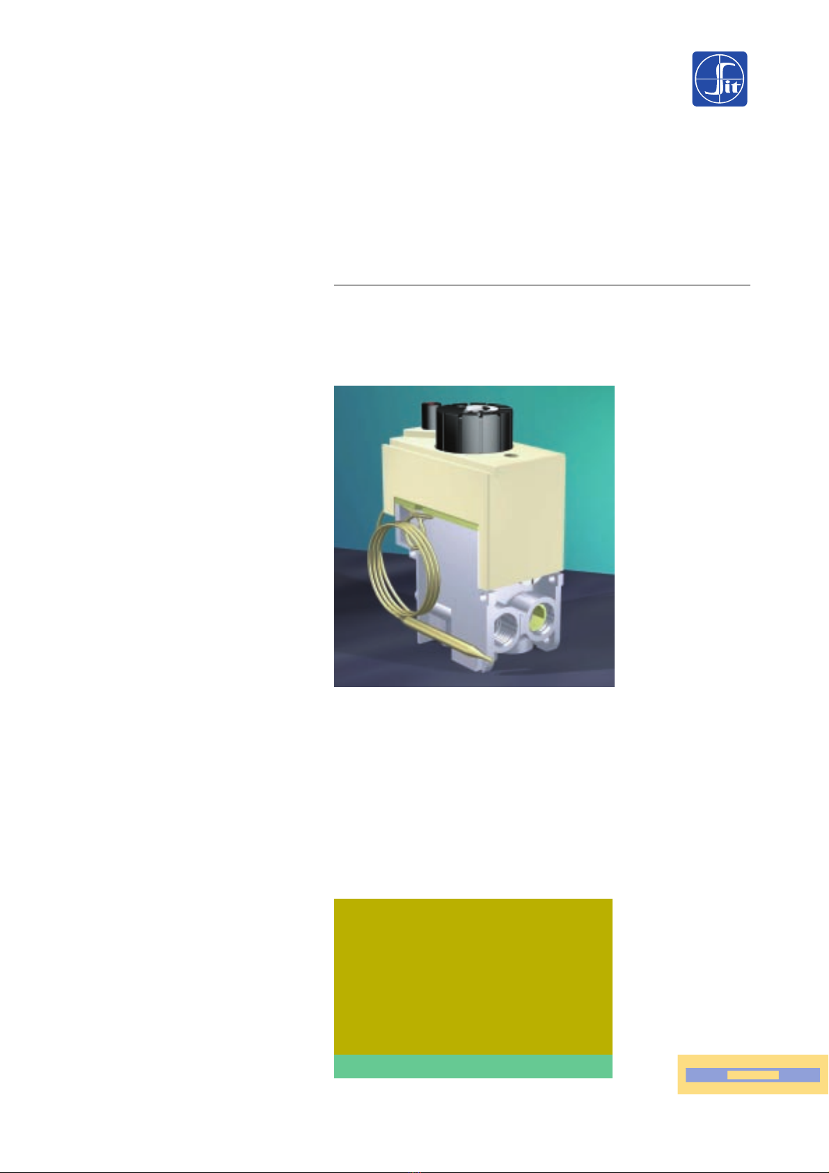
630 EUROSIT
SINGLE-KNOB CONTROL
(TEMPERATURE ADJUSTMENT, PILOT, OFF)
COMBINED MODULATING-SNAP ACTION
ON/OFF THERMOSTAT AT LOW SETTING
SIT Group
MULTIFUNCTIONAL GAS CONTROL
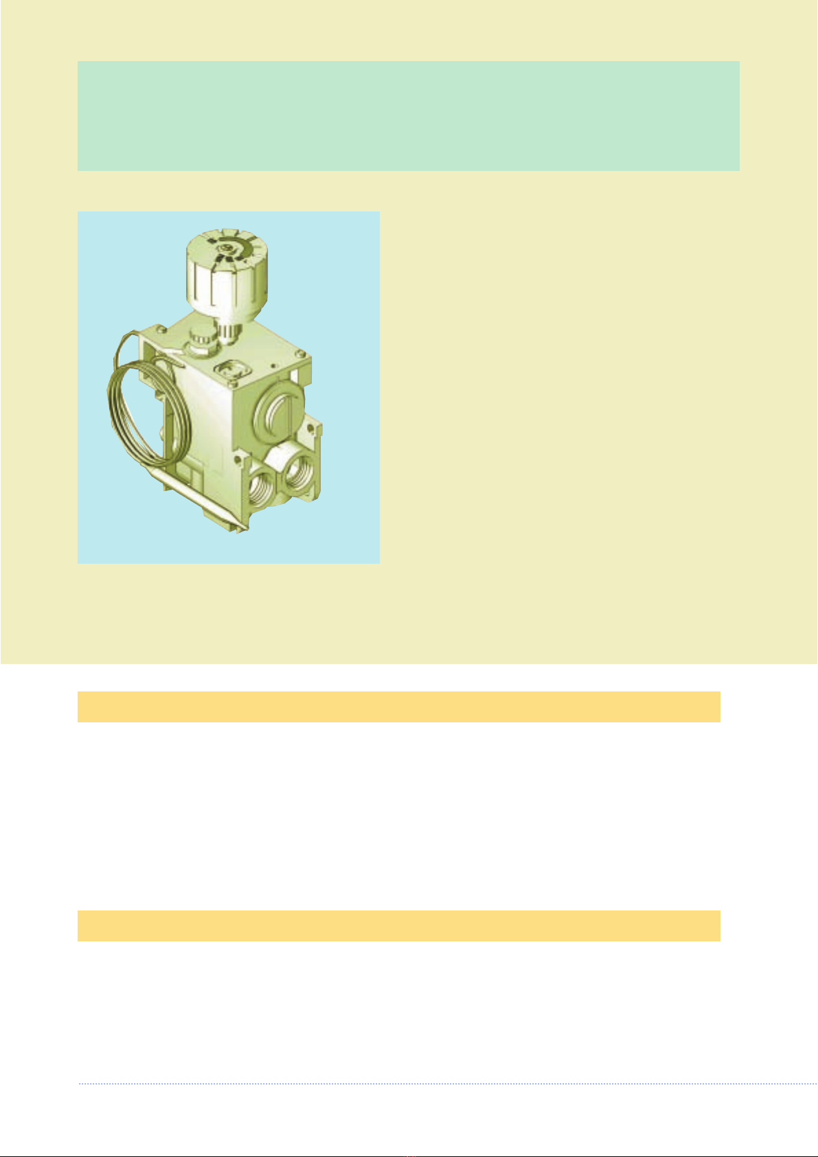
MAIN FEATURES
Single-knob multifunctional
control with thermoelectric
safety device and: interlock
device to prevent improper
operation, pressure regulator
and combined modulating-
ON/OFF thermostat. No exter-
nal power supply required.
MULTIFUNCTIONAL THERMOSTATIC
CONTROL
Manually operated gas valve. (Single knob operation)
Thermoelectric flame failure device.
Snap acting ON/OFF and modulating thermostat. (Optional)
Latching device (Interlok) which prevents incorrect ignition operation.
Pilot outlet suitable for 3/16” or 1/4” tubing.
Pilot flame adjustment.
Inlet and pilot filter.
3/8” NPT threaded gas inlets and outlets.
Inlet/Outlet pressure test ports.
Remote adaptor. (Optional)
Pressure regulator. (Optional)
630 EUROSIT is suitable for use with space heaters,
convectors, storage water heaters, boilers, catering
equipment and all gas appliances requiring
temperature control.
ACCESSORIES
Main accessories available upon request:
• cover
• cover with piezoelectric ignitor
• pilot shear off nut and olive
• remote adaptor
• cables for piezoelectric ignitor
• threaded plugs to close inlets and outlets which are not used

TECHNICAL DATA
DESCRIPTION
• Gas connections:
3/8” NPT X 3/8” NPT
• Mounting position: Multipoise
• Gas types: NG and LPG
• Maximum inlet pressure:
1/2 PSIG
• Outlet pressure setting range:
3.5” to 8.0” W.C. NG (8.0”-12.0” LPG)
• Working temperature range:
32 °F - 175 °F.
6 Inlet pressure test point
7 Outlet pressure test point
8 Pilot outlet
9 Thermocouple connection
10-11 Gas inlet
12-13 Gas Outlet
14 Mounting holes
1 Temperature sensing bulb
2 Outlet pressure adjustment screw
(Version with pressure regulator)
3 Minimum rate screw
4 Temperature setting knob
5 Pilot adjustment screw
▲▼
▲
▲
THERMOSTAT FEATURES
Thermostat range
a b c
55-100 °F 2.7 2.7 1.8
55-118 °F 4.5 4.5 2.7
Other ranges are available on request
Temperature
b
ca
Gas flow rate
5
3
1
8
7
9
10 11
12 13
14
2
6
4

DIMENSIONS
Capacity [BTU/hr]
NG NG
No Pressure Pressure
Regulator Regulator
55.000 40.000
The above capacities are based on Natural gas having a
heating value of 1.000 BTU per cu. ft., and a specific gravity
of 0.64 at a pressure drop of 1” W.C.
For Propane, (Liquefied Petroleum Gas), multiply by 1.62.
Pilot flow rate 2.5 °Ft3/hr at 0.5” Pressure Drop
CAPACITY
Ø 0.2 3 HOLES
0.91
1.97
1.48
0.98 2.09
2.76
0.49
0.59 0.26
3/8-18 NPT
3/8-18 NPT
11/32 ASA
7/16-24 UNS
Ø 1.57
0.2
2.224
0.118
1.3
0.28 0.39
0.35 5.32
1.52
0.5 0.98 0.5
0.98
3/8-18 NPT
3/8-18 NPT
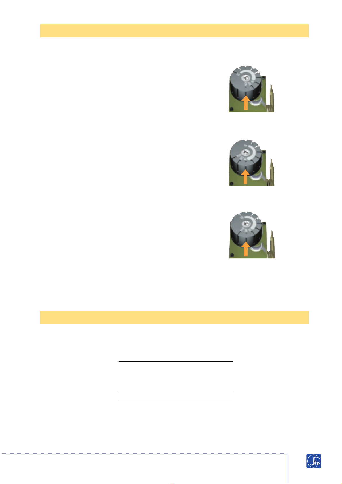
Start up procedure
Turn knob to the OFF position; wait 5 minutes, turn knob until it
stops in the pilot position (PILOT) (fig. 1).
Depress knob and ligtht the pilot, keeping the knob depressed for
about 60 seconds.
Release the knob and check that the pilot flame stays on. If it goes
out, repeat the ignition operations.
Temperature setting
Turn the knob to the desired temperature setting. The maximum
temperature is obtained with the knob turned fully counter-
clockwise (HI position) (fig. 2).
Temporary shut-down procedure
To turn off the main burner only, turn the knob clockwise to the
pilot position (PILOT).
Complete shut-down procedure
Turn control knob to the OFF position (fig. 3).
WARNING:
This control has an interlock device; after shutting off all gas flow,
relighting of the pilot burner can not occur until the thermocouple
has cooled; allowing the electromagnet to be released (approx. 60
seconds).
The gas control knob is designed to be used by hand. DO NOT use
any tools during this operation. Damaged knobs may result in
serious injury.
OPERATION
REGULATOR CHARACTERISTICS
Range Minimum Maximum
Regulated Regulated
Capacity Capacity
(BTU/hr.) (BTU/hr.)
NG 3.5”-8.0” W.C. 10.000 40.000
fig. 2
fig. 3
fig. 1

630 EUROSIT valves conform to all current safety standards. All operations of installation,
calibration, or regulation must be undertaken exclusively by qualified personnel following
the instructions specified in this catalog and those in the instruction manual of the
appliance in which this valve is installed. Any other operation should be avoided.
WARNING
This control is not field serviceable, all adjustments must be done in the O.E.M. factory.
Mechanical connections
General reccomendations: do not tamper with sealed parts. Do not loosen assembly screws. Do
not remove labels. Avoid shocks to the valve (impact, falls, etc.) Remove inlet/outlet dust caps
only at the time of installation. Do not exceed reccomended torque values. Ensure that gas
flow follows arrows on the valve body. Prevent foreign matter from entering the valve during
mounting. In particular, check that the inlet/outlet pipes are clean. Mounting of Eurosit is to be
done using the three mounting holes.
Main gas connection
The connection must be made using properly reamed pipes with 3/8” NPT thread. Apply a
moderate amount of a good quality pipe dope and apply 23 Lb./Ft. of torque. The multi-
functional control is provided with two main inlets and outlets. It is therefore necessary to
close the inlet and outlet which are not used, by screwing the provided plug fully in.
Torque 5.2 Lb./Ft.. Do not overtorque as this could cause distortion of pipe, leakage, and
or malfunction of control.
Pilot gas connection
Connect pilot gas tubing using proper 1/4” or 3/16” shear off nut and olive. Tighten finger
tight, plus one turn with a wrench to assure a good seal.
Thermocouple connection
Insert threaded end of thermocouple into control. Tighten the fixing nut finger tight, plus
1/4 turn with a wrench to assure a good electrical connection.
Testing
After all connections have been made, check all seals and gas connections for leaks, then
set the appliance into operation to assure it is functioning correctly.
INSTALLATION

SETTINGS AND ADJUSTMENTS
Pressure readings
Inlet pressure can be checked by turning cap-
tured screw (6) counterclockwise 2 or 3 turns
then placing tube from gauge over test point.
Outlet can be checked in the same manner as
above, except by using captured screw (7).
Warning: After taking pressure readings, be
sure to turn captured screws clockwise firmly
to reseal. Do not overtorque.
Setting the thermostat
The thermostat (1) is set and sealed at the fac-
tory.
Gas flow
(Vented Units Only)
Maximum flow rate can be checked by cooling
the thermostatic bulb below room temperatu-
re and turning the knob (4) counterclockwise
to the HI position. Minimum flow rate can be
checked by cooling the thermostatic bulb
below room temperature and slowly turning
the knob counterclockwise and stopping when
you hear the snap. This flow rate is preset by
the O.E.M. at the design stage, and is set with
a pre-drilled minimum rate screw.
Pilot adjustment
(Vented Units Only)
Use a screwdriver to adjust the screw (5) to
achieve the desired pilot flame. Clockwise
decreases the amount of gas to the pilot.
Adjusting the pilot gas flow
7
6
Pressure readings
4
5
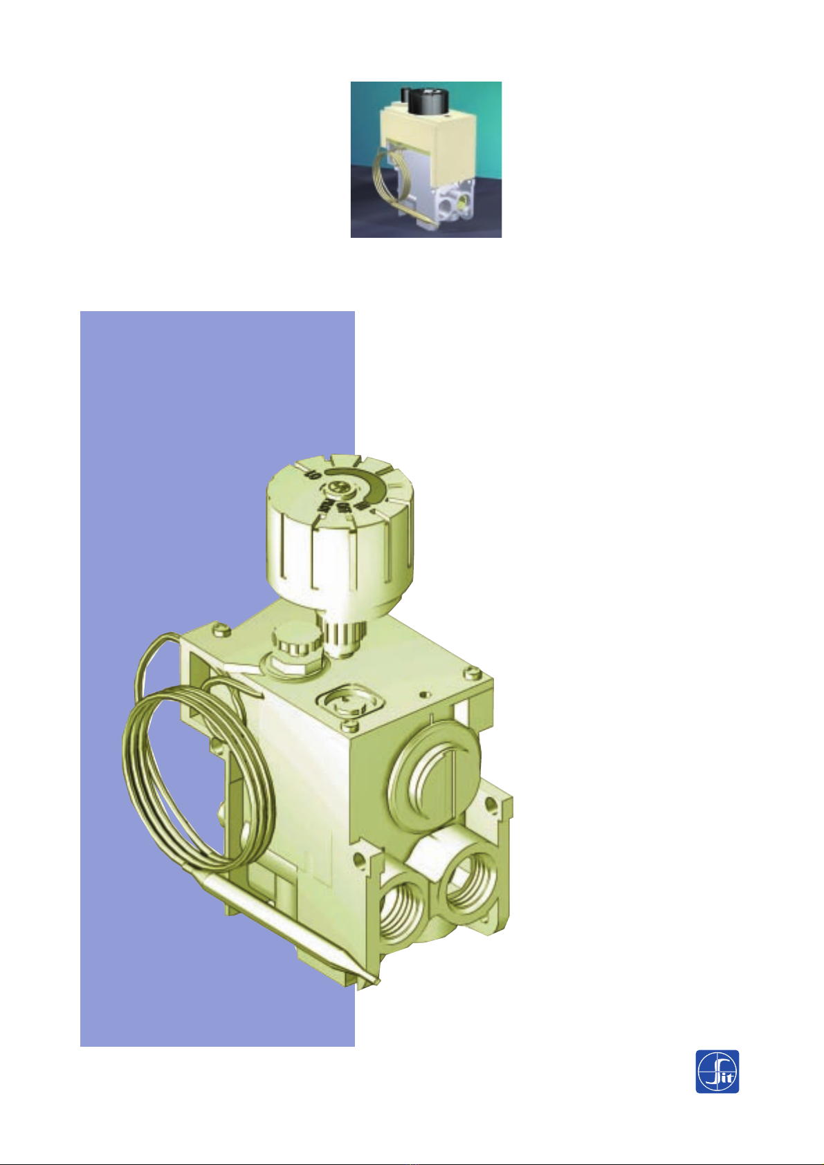
630 EUROSIT
Single-knob multifunctio-
nal control with combi-
ned modulating-ON/OFF
thermostat, for gas
appliances without
external electric power
supply.
S.I.T. Controls USA, Inc.
Subsidiary of SIT La Precisa Srl
8100 - G Arrowridge Blvd., Charlotte, N.C. 28273 USA
Telephone: (704) 522.6325 - Telefax (704) 522.7945
Cod. 9.955.729 - R00
Other manuals for 630 Eurosit
2
Other Sit Controllers manuals


