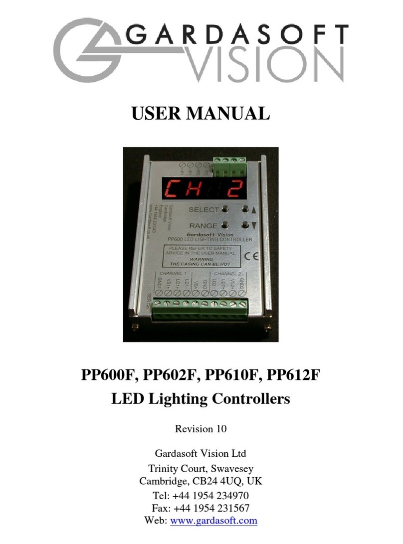
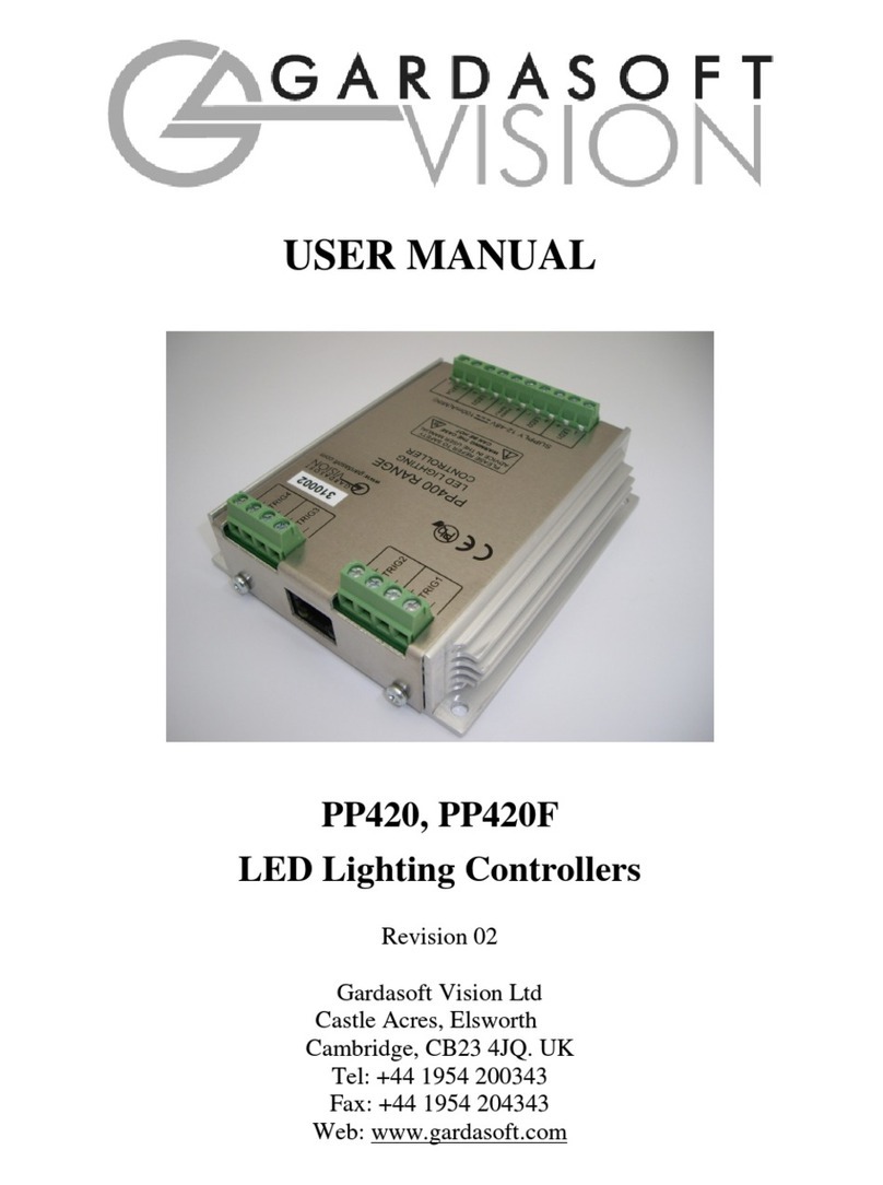
Gardasoft Vision PP860 User manual

USER MANUAL
PP860, PP861
LED Lighting Controller
Revision 05
Gardasoft Vision Ltd
The Merchant’s House, High Street,
Fen Drayton, Cambridge, CB4 5SJ, UK.
Tel: +44 1954 200343
Fax: +44 1954 204343
Web: www.gardasoft.com

2
1Disclaimer
Except as prohibited by law:
All hardware, software and documentation is provided on an “as is” basis.
It is essential that the user ensures that the operation of the product is
suitable for their application.
The user must ensure that incorrect functioning of this equipment cannot
cause any dangerous situation or significant financial loss to occur.
Gardasoft Vision Ltd and Gardasoft Products Ltd will not accept any
liability for consequential loss of any kind.
All trademarks acknowledged.
Hardware, software and documentation are Copyright 2002 – 2006 Gardasoft
Products Ltd. Hardware manufactured by Gardasoft Vision Ltd under licence.

3
2Getting Started
Throughout this manual, references to the PP860 refer to the PP860 and PP861
unless otherwise stated. The symbol “us” is used to denote microseconds.
Read the sections on Safety and Specifications and check the PP860 fulfils
your requirements. Gardasoft Vision also produce other controllers which are
listed on our website.
Connect the PP860 up to a supply and an LED lighting unit as described in
“Connections”.
Read the section on “Operation” and set up the PP860 to supply a small
continuous current to the LED unit. Check that the LED unit illuminates.
Refer to the Serial Control section and read how to send RS232 commands.
Mount the PP860 as described in “Mechanical Fixing” using the mounting
holes. In particular read the notes on heatsinking. Set up the PP860 for the
desired operation and test.
Visit www.gardasoft.com for Application Notes on this product.

4
3Safety - English
3.1.1 PP860 – Safety
Please read this before using the PP860 family of products. If in doubt, contact
your distributor or Gardasoft Vision.
3.1.2 Heat
The PP860 can get very hot. It should be positioned where personnel cannot
accidentally touch it and away from flammable materials.
Do not exceed the power ratings given in the manual. Note that at the
maximum ratings the case temperature can reach 80oC.
If the output load is short circuited then the heat dissipated within the unit will
greatly increase, resulting in a further rise in temperature.
3.1.3 Electrical
The user must ensure that the potential difference between any combination of
applied signals does not exceed the supply voltage. WARNING: Higher
voltages may cause a danger to personal health.
The PP860 does not have complete tracking isolation of inputs and outputs.
Transients caused by inductive loads must be suppressed external to the PP860.
3.1.4 General
The PP860 must not be used in an application where its failure could cause a
danger to personal health or damage to other equipment.

5
4Safety - German
4.1.1 Sicherheitshinweis PP860
Bitte lesen Sie sich diesen Sicherheitshinweis gründlich durch, bevor Sie die
Produkte der Serie PP860 benutzen. Sollten dennoch Zweifel Ihrerseits
bestehen, zögern Sie nicht sich mit uns in Verbindung zu setzen.
4.1.2 Wärmeentwicklung
Die Geräte können während des Betriebes sehr heiss werden. Sie sollten daher
dort untergebracht sein, wo Personen keine Brandverletzungen erleiden können
und wo sich keine entflammbaren Materialen befinden.
Überschreiten Sie nicht die im Manual angegeben Höchstspannungen.
Beachten Sie, dass die Temperaturen bei max. Spannung bereits 80°C betragen
können.
Wird pro Kanal mit hohen Blitzspannungen und kurzen Blitzzeiten gearbeitet,
steigen die Temperaturen nochmals an!
4.1.3 Elektrischer Betrieb
Stellen Sie sicher, dass die Spannungsdifferenz zwischen jeder Kombination
angelegter Signale nicht die Versorgungsspannung übersteigt. ACHTUNG:
Höhere Spannungen können sich Gesundheitsgefährdend auswirken.
Ein und Ausgänge haben keine komplette Leiterbahnisolierungen.
Überschläge, die aus Induktion resultieren können, müssen ausserhalb des
PP860 abgehalten werden.
4.1.4 Generell
Die Controller der PP860 Serie sollten nicht in Applikationen eingesetzt
werden, in welchen ein Fehlverhalten des Gerätes gesundheitliche Schäden
verursachen könnte oder technische Ausrüstung zerstören könnte.

6
5Safety - French
5.1.1 PP860 - Consignes d’utilisation
Veuillez lire attentivement ces consignes, avant utilisation de la gamme des
produits du PP860. En cas de doute n’hésitez pas à contacter votre revendeur
ou GardaSoft Vision.
5.1.2 Chaleur
Le PP860 peut atteindre une température très élevée. Il ne doit pas être placé à
proximité d’une source de chaleur ou de matériel inflammable, ou à la portée
du personnel, risque de brûlure.
Respecter les puissances requises dans le manuel d’utilisation. Noter que le
contrôleur peut atteindre 80°C.
En cas de court circuit, la chaleur qui se dissipe à l’intérieur du boîtier va
fortement augmenter, ce qui entraînera une augmentation supplémentaire de
température.
5.1.3 Electrique
L’utilisateur doit s’assurer que la différence de potentiel des combinaisons ne
doit pas excéder la tension de l’alimentation.
ATTENTION ! Une tension trop élevée pourrait entraîner de graves
conséquences sur la santé du personnel.
Toutes entrées et sorties du PP860 ne sont pas complètement isolées.
5.1.4 Généralité
Le PP860 ne doit pas être utilisé dans les conditions mentionnées ci-dessus ;
sous peine de conséquences graves sur la santé du personnel ou
d’endommagement d’autre équipement.

7
6General Description
The PP860 current controller provides repeatable intensity control of LED
lighting for machine vision applications. It includes the power supply, intensity
control, timing and triggering functions required for machine vision systems.
LED lighting needs a constant current supply as small variations in voltage can
cause large variations in light output. Currents can be specified in 0.1A steps.
Two modes of operation are provided separately for each channel:
Continuous:
In continuous mode the output is a continuous current.
Strobed:
In this mode output is pulsed once per trigger. One input is used as a
trigger. The pulse width can range from 0.1us to 2ms in 0.2us steps. The
delay can range from 5us to 2ms in 0.2us steps.
Triggers occur on the leading edge of the input, that is on the transition from a
logic 0 to logic 1. Output 1 is triggered from INPUT 1, output 2 from INPUT 2,
etc.
Configurations can be saved in non-volatile memory so that the PP860 will
resume operation after a power cycle.
The pushbutton on the side of the unit is currently unused.

8
7Specifications
Parameter Value Notes
Supply voltage
(VS)
10V (min)
35V (max)
The supply voltage must be at
least 1V above the forward
voltage of the lighting being
driven. Ideally set this voltage as
low as possible to reduce the
total unit power dissipation.
Quiescent supply
current (IS)
15mA at VS=
48V
33mA at VS=
20V
PP860: 2A
continuous or
20A pulsed
Output current
per channel (il)PP861: 2A
continuous or
2A pulsed
Maximum allowed current per
channel. Average current when
pulsing must not exceed the
maximum allowed continuous
output.
Total allowed
unit power
dissipation in free
air
P
D
=10 Watts
(max)
Total unit power
dissipation with
heatsink
P
D
=20 Watts
(max)
The total unit power dissipation is given by (0.7W) plus the sum of (VS-VF) * IL
for each current output where:
IL = Average output load current (Amps)
VF = Load forward voltage
VS = Supply voltage

9
8Mechanical Fixing
The PP860 can be mounted onto a flat surface using the threaded holes in the
base, see diagram.
The enclosure of the PP860 is used to dissipate power in the form of heat. For
this reason the material to which the unit is attached must be suitable,
preferably metallic with ability to dissipate the produced heat. This is
particularly important if the power dissipation of the PP860 (as defined by PD
the section on Specifications) exceeds 10 Watts.

10
9Connections
9.1 General
The RS232 and trigger connections are made using D-type connectors. The
power input and output connectors are
The connectors are arranged as follows:
9.1.1 Trigger Inputs
The trigger input connector is a 9-way D-type male.
The trigger connector pinout is given below. Each input consists of a 1K
resistor in series with an opto-isolating LED. If the voltage applied is open
circuit or less than 1V then the input is a logic 0. If the voltage is 5V to 24V
then the input is a logic 1.
Pin Function
1Input 4 positive
2Input 3 positive
3Input 2 positive
4Input 1 positive
5Input 0 positive
6GND (connected to PSU GND)
7Input 7 positive

11
8Input 6 positive
9Input 5 positive
9.1.2 Power Input
The pinout of the power input connector is:
Pin Function
1Supply positive
2Supply GND
The case of the PP860 is not connected to the GND supply
connection.
9.1.3 Power Outputs
Each power output connector has the connections for two output channels. The
connectors are
The pinouts are:
Pin Function
1First channel positive
2First channel negative
3Second channel positive
4Second channel negative
9.1.4 Serial Connector
The RS232 connector is a standard 9-way female D-type connected as follows.
A standard straight through cable can be used to connect the PP860 to a PC
serial port.
Pin Function
2TX (output from PP860)
3RX (input to PP860)
5GND

12
10 Serial Commands
10.1 Command Structure
The PP860 can be programmed via a serial communications link either from
within the user’s custom code using MSCOMMS32 or using a Gardasoft
demonstration program (check availability then download from
www.gardasoft.com ) . Alternatively a utility such as HyperTerminal running
on a PC can be used to program an individual unit.
The communications port should be set to 115Kbaud, no parity, 8 data bits, 1
stop bit.
The commands comprise a code of two upper case letters followed by the
parameters (if any) needed for the command. Spaces in the commands are
ignored. A carriage return character should be sent to terminate the command.
Time is defined in microseconds:
20 20us
1500 1.5ms
Current is in amps
0.2 0.2A
1.5 1.5A
20 20A
All responses from the PP860 are terminated with a ‘>’ character to indicate
that the command is complete.
If a command is invalid, one of the following error codes from Appendix A
returned.
Commands take effect immediately they are issued. Because of this, if the
settings are being changed from high current Pulsed Output mode to a
Continuous Output mode, it is advisable to set the current values to 0
using the RC command before changing mode. This prevents overload
conditions occurring.
Any changes made using RS232 commands are not saved permanently
until the AW command has been issued.

13
10.1.1 General Commands
AW Save the settings to memory.
Syntax: AW
Once the settings are saved to memory they are then retained when the
unit is switched off. If this is not done, changes to the settings are volatile,
and if the unit is switched off they revert to those in force when the last
AW command was issued.
ST Report the current settings for the outputs
Syntax: ST
The first four lines of the response report the output settings. The format
is either:
f M m V a For Constant Mode
f M m C a D d P p For Pulsed Output Mode
Where:
f output channel
m is one of:
0 Not set up
1 Pulsed output
2 Continuous output
a Output current (amps)
p Pulse width (microseconds)
d Delay before pulse (microseconds)
VR Report the version of firmware running in the PP860
Syntax: VR
Response: version
10.1.2 Continuous Output Mode
In this case the mode of operation is selected and a single current output value
defined.
RS Set continuous operation
Syntax: RSf,a
Where:
f = output channel (0 to 7)
a = output current (A)
Example of Continuous Output Mode

14
Set a continuous current of 0.5A on output channel 3
RS3,0.5
10.1.3 Pulsed Output Mode
RT Set the pulse parameters.
This command sets a channel to pulsed output. Note that output channel 1 can
only be triggered by INPUT1 and output channel 2 can only be triggered by
INPUT2, etc.
The pulse delay can be from about 2us to 20ms. The pulse width can be any
value from 1us to 20ms.
Syntax: RTf,p,d,a
Where:
f = output channel (0 to 7)
p = pulse width (microseconds)
d = delay from trigger to pulse (microseconds)
a = output current (A)
Example of Pulsed Output Mode
Set channel 2 to pulsed output at 4A, pulse a continuous current of 0.5A
on output channel 3 for 1ms after a delay of 500us
RT2,1000,500,4

15
A. Error Codes
Error codes may be displayed by the PP860. These are shown as “E nn”, where
nn gives the number of the error. The error codes are:
Et
The PP860 has a thermal cutout. If the internal temperature reaches 62oc,
which corresponds to a case temperature of approximately 60oc, the
output currents are turned off. This message will persist until the PP860
has cooled down below 60oc.
E1
One of the parameters to a command has an illegal value.
E2
On power up, the stored configuration was invalid.
E4
The RS232 command has the wrong number of parameters.
E16, 17, 18
Invalid command.
E 40
When the unit has powered up the non-volatile memory was corrupt and
has been cleared. Set up the unit again.
All other errors
A hardware error has occurred. Try power cycling the unit and trying
again to see if the fault clears. If not, make a note of the number and
contact your distributor.

Gardasoft LED Lighting Controllers
The following products are available at the time of writing. New products will
be introduced. See www.gardasoft.com for details of the current range.
PP600 Range
•2 output channels up to 10A each
•2 digital inputs
PP600 Lighting controller
PP610 Lighting controller with RS232
PP701 DIN Rail mounting clip for PP600 and PP600F range
PP600F Range
•Same as the PP600 range but with fast pulsing
•Pulse delay from 10us to 9.9ms in 1us steps
•Pulse width from 1us to 9.9ms in 1us steps
PP600F Lighting controller
PP610F Lighting controller with RS232
PP900 Range
•1 output channel up to 1A
•Supports voltage and current rated lights
•1 digital input
•SafesenseTM Technology
•Light sensor feedback
PP900 Auto sensing lighting controller
PP910 Auto sensing lighting controller with RS232
PP860, PP861
•High current, high accuracy controller
•8 output channels up to 20A each
•Pulses repeatable to 0.1 microseconds
•RS232 configuration
This manual suits for next models
1
Table of contents
Other Gardasoft Vision Controllers manuals
Popular Controllers manuals by other brands

Emerson
Emerson EIM E796 M2CP Installation and maintenance manual

phytron
phytron MCC-1 manual

Extron electronics
Extron electronics Basic MediaLink Controllers MLC 52 IR user manual

Tapeswitch
Tapeswitch PSSW Technical manual

Pontec
Pontec PondoSolar 250 Control operating instructions

Murphy
Murphy Autostart 710 AS710S owner's manual