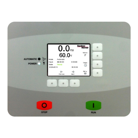
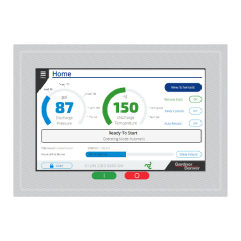
Gardner Denver GD PILOT TS Series Quick guide

USA ZS1133369 / 00 - January 2015
Translation of the original operating
instructions
Compressor control
GD PILOT TS / L series

Table of Contents
TM
2 / 80 USA January 2015
TABLE OF CONTENTS
1 Foreword........................................................ 3
1.1 About these operating instructions............3
1.2 Intended use............................................. 3
1.3 Foreseeable misuse..................................3
1.4 Service...................................................... 3
2 Safety requirements......................................4
2.1 Labeling of safety instructions...................4
2.2 Safety symbols..........................................4
3 Control panel and controller........................8
3.1 General operation / Parameter entry.........8
4 Menus........................................................... 10
4.1 Menu structure........................................ 10
4.2 "Home" menu..........................................10
4.3 Pictogram................................................ 14
4.4 "Trends" menu........................................14
4.5 "Settings" menu...................................... 16
4.6 "Fault History" menu.............................. 20
4.7 "Access Code" menu............................... 20
5 Configuration...............................................22
5.1 Choose Language...................................22
5.2 Set the Date and Time............................22
5.3 Setting units of measure......................... 23
5.4 Additional settings...................................25
5.4.1 Setting pressure bands........................... 25
5.4.2 Program Inputs and Outputs...................27
5.4.3 Timer Control.......................................... 31
5.4.4 Programming the Dryer Pre-Run
Time........................................................ 35
5.4.5 Setting RS485 communication................36
5.4.6 Setting the automatic restart after power
loss.......................................................... 37
5.4.7 Setting remote start/stop.........................38
5.4.8 Remote On-Load and Off-Load (FS).......39
6 Operating..................................................... 40
6.1 Stopping the compressor in case of
emergency...............................................40
6.2 Starting the compressor..........................40
6.3 Factors that inhibit starting......................40
6.4 Operation.................................................41
6.5 Operating Modes.................................... 41
6.6 Stop the compressor...............................41
6.7 Operation Monitoring.............................. 41
7 Clearing a fault............................................ 43
7.1 Checklist for clearing faults..................... 43
7.2 Structure of fault and warning codes.......43
7.3 Troubleshooting.......................................44
8 Additional controls..................................... 52
8.1 Maintenance level................................... 52
8.2 Additional trend charts at the maintenance
level......................................................... 52
8.3 Resetting Statistics On-Load Hours........ 53
8.4 Set the Service interval...........................53
8.5 Data Recording....................................... 54
9 Setting Up a Replacement Controller........56
9.1 Setup Code and Compressor Reference
Number....................................................56
9.2 Setting up a replacement controller........ 56
10 Base Load Sequencing (BLS)....................59
10.1 Base Load Sequencing...........................59
10.2 Supported slave controllers.................... 59
10.3 "Base Load Sequencing" menu............... 60
10.4 Compressor status messages................ 62
10.5 Compressor Settings and Information.....63
10.6 Base Load Sequencing Settings.............64
10.7 BLS Functional Description.....................66
10.8 Trend and History Charts........................67
10.9 Installing the RS485:3 module................ 68
10.10 Installing the compressor module
(STD).......................................................69
11 Appendix...................................................... 74
11.1 Status messages.................................... 74
11.2 Settings................................................... 75
TM
Foreword 1
January 2015 USA 3 /80
1 FOREWORD
1.1 About these operating
instructions
These operating instructions contain information
about controllers for fixed-speed or variable-speed
compressors, and for water-cooled or air-cooled
compressors.
Special sections are marked accordingly:
(FS) (fixed speed); for compressors with a fixed
speed
(RS) (regulated speed); for compressors with
speed control
(A) (air); for air-cooled compressors
(W) (water); for water-cooled compressors
All entries shown (parameters, settings, and con-
figurations) are examples and do not apply to spe-
cial applications. They are not specific values for a
particular model of compressor.
The controller type GD PILOT TS is intended
for use exclusively with compressors from the L
Series from Gardner Denver.
This operating instructions are valid for the con-
troller type GD PILOT TS with software versions
DXL-L(RS)-2.0x and higher.
Requirements for personnel
Only assigned personnel may work on the con-
troller and compressor. Personnel are trained and
instructed on the compressor.
The responsibilities of personnel for operation,
maintenance, and repair must be clearly defined.
The work of personnel should be checked regu-
larly to make sure that all work is done with the
personnel being aware of safety and hazard is-
sues.
Personnel in training, under instruction, being
taught, or taking part in a general training program
may work with the controller and compressor only
under the continuous supervision of an authorized
person.
For safety-relevant changes to the compressor
or its operating behavior, the compressor must
be stopped immediately and the fault must be re-
ported to the responsible area or person.
Faults, especially those that can compromise
safety, must be corrected immediately. Otherwise
the compressor must not be operated.
Work on electrical equipment may be performed
only by an appropriately qualified electrician, in ac-
cordance with electrical engineering regulations
and specifications.
Reference documents
These operating instructions only describe the
controller type GD PILOT TS.
In addition to these operating instructions, the op-
erating instructions for the compressor must be
followed.
1.2 Intended use
The installed controller type GD PILOT TS is in-
tended for use exclusively with compressors from
the L Series from Gardner Denver.
1.3 Foreseeable misuse
Any changes to the software or hardware of the
controller must be approved by Gardner Denver.
1.4 Service
If you have any questions about or problems with
the compressor please consult your Gardner Den-
ver representative.
Trained and specialized personnel provide fast,
technically accurate assistance.
In case of queries
If you have a query or wish to make a spare parts
order, please specify the model, the identification
number and year of manufacture as indicated on
the name plate. Providing these data ensures that
you will receive the correct information or spare
parts.
Your Gardner Denver representative
Please enter the details of your local Gardner
Denver agency in the following table.
Name:
Contact person:
Address:
Telephone
Fax
Email:
Chart 1-1: Local Gardner Denver representative

2 Safety requirements
TM
4 / 80 USA January 2015
2 SAFETY REQUIREMENTS
Gardner Denver takes no responsibility for prop-
erty damage or injuries that result from failure to
follow the safety requirements
In additional to these operating instructions, the
operating instructions for the compressor must be
followed.
2.1 Labeling of safety instructions
Safety instructions are used as special warning
notices in the operating instructions, using the fol-
lowing names and symbols.
These special warning notices serve to protect
against hazards and are close to the potential haz-
ard in space and time:
On the system, near the source of hazard
In the operating instructions, before a se-
quence of actions or activities to be performed
is described
Structure of safety instructions
The special warning notices in the operating in-
structions are structured as follows:
ALERT WORD
Safety
symbol
Hazard (consequences of haz-
ard)
Description of the hazard (source)
Protective measure (protection
against hazard)
Components of safety instructions
Hazard (consequences of hazard): The hazard
sequence tells the type of hazard.
Description of the hazard (hazard source ): The
hazard source indicates the cause of the hazard.
Protective measure (protection against haz-
ard): The protection against the hazard describes
the measures for preventing the hazard.
Alert word: The alert word classifies the severity
of the hazard into four levels, emphasized graphi-
cally with different colors. The alert word is used in
the safety instructions as described below.
DANGER Indicates an immediate dangerous sit-
uation that, if not prevented, will result in death or
extreme (irreversible) injury.
WARNING Indicates a potential dangerous situ-
ation that, if not prevented, can result in death or
extreme (irreversible) injury.
CAUTION Indicates a potential dangerous situa-
tion that, if not prevented, can result in slight or mi-
nor (reversible) injury.
CAUTION Indicates information or recommenda-
tions that directly or indirectly relate to the safety
of persons or equipment protection.
2.2 Safety symbols
The safety symbols (hazard warning signs) can be used in the operating instructions and in the environ-
ment around the compressor.
Safety symbol Meaning Use / Behaviour
General hazard Warning of a general hazard.
Observe the warning and proceed with the required cau-
tion (e.g., protective clothing) and care.
Slip hazard Warning of a slip hazard.
Use caution when walking, running, or climbing.
Component or system
under pressure
Identification of devices or areas in which the air pres-
sure is substantially higher than in the normal atmos-
phere.
Do not open devices or chambers until the pressure has
been equalized.
Chart 2-1: Safety symbol

TM
Safety requirements 2
January 2015 USA 5 /80
Safety symbol Meaning Use / Behaviour
Do not operate with open
doors or loose enclosure
panels.
It is not permitted to run the compressor with open doors
or loose enclosure panels, except for test runs. High
sound pressure level, risk of injury!
Normal operation requires the enclosure to be closed.
Do not breathe in the
compressed air from this
unit
It is not permitted to use the compressed air produced by
this compressor for breathing. Indrawn materials can be
dangerous to health.
Do not use compressed air as breathing air.
Electrical voltage Warning against dangerous electrical voltage.
Work on the electrical equipment of the compressor may
be done only by an electrician in accordance with electri-
cal rules.
System continues to run After pressing the stop button <O>, the compressor runs
on for 30 seconds.
Do not open the compressor enclosure until the com-
pressor has stopped.
Follow the operating
instructions
Identification of instructions where additional information
can be found in the (manufacturer’s) operating instruc-
tions.
Before the device is operated, the user (operator) must
have read and understood the operating instructions
(manufacturer’s operating instructions).
Use hearing protection Identification of areas with increased sound pressure
level.
Enter the area only with suitable hearing protection.
Warning against indus-
trial trucks
Warning of industrial trucks traveling within the plant
(e.g., forklifts).
Do not perform any work in traffic lanes with limited visi-
bility that are not secured or blocked off. Use or crossing
of this traffic lane requires great caution.
Warning of suspended
loads
Warning of suspended loads being transported.
During transport, no person may be present in the haz-
ard area. In particular, do not reach in or allow the feet to
pass beneath the suspended compressor.
Warning of moving
machine parts.
When performing maintenance work, it is necessary to
check some functions with the enclosure open. Risk of
injury due to rotational or translational motion.
Maintenance work may be performed only by specially
trained technicians.
Chart 2-1: Safety symbol

2 Safety requirements
TM
6 / 80 USA January 2015
Safety symbol Meaning Use / Behaviour
Warning of hand injuries Hazard that the hands may be crushed, drawn in, or oth-
erwise injured.
Keep clear.
Warning of automatic
start-up
In normal operation the compressor can start automati-
cally at any time. Operational readiness of the compres-
sor is indicated by the green LED on the control panel.
Do not perform any work on the compressor when the
green LED is lit.
Warning of hot surfaces Parts of the compressor become very hot when in opera-
tion (up to 235 °C). Risk of injury from hot surfaces.
Before beginning maintenance and repair work, the com-
pressor must have cooled off sufficiently.
Warning of suffocation Suffocation hazard due to insufficient exhaust extraction
and ventilation of the compressor room.
The operator must provide sufficient exhaust extraction
and ventilation of the compressor room.
Warning of crushing haz-
ards
Warning of crushing hazards caused by a piece of equip-
ment (e.g., a machine) or structural components (e.g.,
covers, enclosures, guards, fences) during transport.
Working at the marked workstations requires increased
vigilance.
Do not go / stand
beneath the load
Do not go / stand beneath a suspended load. The driver
is not allowed to drive the industrial truck if there is a per-
son beneath the load. The driver must also make sure
that no one stands or walks under the load.
The load must be transported so that it is sufficiently
clear of the ground (max. 0.5 m above the ground).
(In Germany also refer to the law BGV D27 “Industrial
trucks”). The driver is responsible for all travel and load
movements of an industrial truck.
Lifting point Identification of lifting points.
Only the indicated lifting points may be used for trans-
port.
XX bar
Safety valve Opening pressure of safety valves (for value “xx” see the
label on the control panel).
Check connection ter-
minals and retighten if
needed. For additional
information, see the
operating instructions.
Warning of loosened clamp connections. Clamping pres-
sure can fade after some time.
Check the clamps regularly according to the safety
guidelines and retighten as needed.
Chart 2-1: Safety symbol

TM
Safety requirements 2
January 2015 USA 7 /80
Safety symbol Meaning Use / Behaviour
10 min
Electrical voltage
Residual voltage on the
capacitors
Warning against dangerous electrical voltage.
Warning of electrical energy stores in the form of capaci-
tors. They carry deadly electrical voltage.
Do not open the electrical switch cabinet (RS compres-
sor) for 10 minutes after disconnecting the compressor.
Check the DC bus voltage of the frequency converter
at the grid terminal strip of the frequency converter. The
exact position of the “DC+” and “DC-” terminals can be
found in the included operating instructions for the fre-
quency converter.
Work on the electrical equipment of the compressor may
be done only by an electrician in accordance with electri-
cal rules.
Spring tension Warning of springs under tension in the interior of the
suction regulator.
Before opening the suction regulator, read the repair
manual.
Bacterial contamination
hazard
Warning of the presence of Legionella in the cooling
water in an open-loop cooling water circuit
Continuous monitoring of the cooling water by mainte-
nance personnel.
Caution: hot liquid Warning of hot oil or hot coolant.
Allow the compressor to cool before opening the fluid cir-
cuit lines.
Chart 2-1: Safety symbol
NOTE
All hazard warning signs must be present and in legible condition.
Check regularly and replace when needed.

3 Control panel and controller
TM
8 / 80 USA January 2015
3 CONTROL PANEL AND
CONTROLLER
Fig. 3-1: Control panel
[1] Touchscreen Display
[2] Start-Taste < I >
[3] Stopp-Taste < O >
[4] rote LED
langsames Blinken: Warnung oder
Wartung
schnelles Blinken: Störung
[5] gelbe LED
langsames Blinken: Wartung erforderlich
[6] grüne LED
Dauerleuchten: Anlage in Betrieb
Blinken: Anlage in Standby (Bereitschaft)
[7] Taster <Not-Halt>
About the compressor controller
The controller is responsible for the following:
Starting and stopping the compressor
Compressor rotational speed control (RS) and
switching the compressor between load and
Off-Load operation in response to variations in
air demand
Monitoring of various operating parameters,
such as pressures and temperatures
Display of warnings and fault messages, and
automatic shut-down when a fault occurs
Data entry for adjustment of various operating
parameters
Keeping track of scheduled maintenance of the
compressor
3.1 General operation / Parameter
entry
Input menus
If parameters must be adjusted or other inputs
must be made in a menu, the appropriate input
menu appears in order to make the input.
The input menus are largely self-explanatory.
Selection
If only certain defined values are available for an
input, appropriate selection input menus are dis-
played.
Control
Operating Mode
OK
Continuous Operation
Cancel
Automatic Operation
Fig. 3-2: "Select” input menu, example: “Operating
Mode”
Control
Remote Start Enabled
OK
On
Cancel
Off
Fig. 3-3: “Select” input menu, example: “Remote Start
Enabled”
The input menus are enhanced with an explana-
tory text where needed.
Control
Periodic Start-Up
OK
Every 24 hours
Cancel
Never
Periodically starts the
motor for a few seconds.
Fig. 3-4: Input menu with explanatory text

TM
Control panel and controller 3
January 2015 USA 9 /80
Parameters
When parameters must be entered, an appropriate
keyboard appears on the screen. The allowable
range is displayed next to the entry for the para-
meter that is being changed.
Control
- Max. Power Loss Time
Setting Range
OK
Cancel
Fig. 3-5: Screen keyboard
Additional information
Instructions for the current menu are given wher-
ever needed.
Timer Control
Select a Setting
Date and Time
Timer Start/Stop
Timer Pressure Band p2
Display / Adjust
Display / Adjust
OK
This page is to set the
Timer Channel only. The Timer for
Compressor Start/Stop or activating the
second Pressure Band must be enabled
within Setpoints Menu.
Fig. 3-6: Menu with additional information
Access Code
Input menus for access codes always have a note
about the status of the current access authoriza-
tion.
Access Code
Input Access Code
Status:
User Settings
Unlocked
Fig. 3-7: Access code input menu
Arrow keys
If the menu contents do not fit on the display, ar-
row keys for scrolling through the menu contents
will appear.
Control
Select a Setting
OK
8.0 bar
Automatic Operation
Off
Off
Off
p2 Timer Enabled
Timer Control Enabled
Remote Start Enabled
p2 Target Pressure
Operating Mode
Fig. 3-8: Menu with arrow keys

4 Menus
TM
10 / 80 USA January 2015
4 MENUS
4.1 Menu structure
Home
On-Load 0rpm345
Hours Run
Hours On-load
Hours to Next Service
Remote Start Enabled
Timer Start Enabled
Auto. Restart Enabled
(1) Home
(2) Trends
Statistics On-Load Hours
Statistics Weekly Profile
Volumetric flow rate
Network pressure
Motor Speed (VS)
(3) Settings
Hour Meters
Controller
Timer Control
Programmable Inputs and Outputs
Communication
Configuration
Factory Settings
SD-Card
(4) Fault History
List of alarms, displaying
Alarm Details
(5) Access Code
Input menu
„
Input Access Code“
(6) Base Load Sequencing (optional)
2
3
4
5 6
1
Date and Time / Language Selection
Operating Display (Pictogram with
Setpoints and Measured Values)
Status / message area
Hours Run / Service hours
Status of switch-on functions
Turn on/off Base Load Sequencing
Settings:
- Setpoints
- Behavior
- Timer Control
- Configuration
Additions at the Service level:
Discharge pressure
- Output temperature
- Heatsink Temperature (VS)
- VSD Output Current (VS)
Base Load Sequencing additions:
- Volume Flow (BLS)
- Statistics Weekly Profile (BLS)
Fig. 4-1: Menu structure
4.2 "Home" menu
The "Home" menu is the basic screen that is shown during normal operation.
This menu is called up via the <Home> register card.
If there is no input for five minutes, this menu will appear automatically.

TM
Menus 4
January 2015 USA 11 /80
Hours On-load
Home
Hours Run
Hours to Next Service
Remote Start Enabled
Timer Start Enabled
Auto. Restart Enabled
1
2
3
4
5
6
7
8
9
10
On-Load 3450rpm
Mo.
Fig. 4-2: "Home" menu
[1] Date and Time [6] Status / message area
[2] Direct access <"Language Selection"> [7] Status of switch-on functions
[3] Volumetric flow rate [8] Register cards
[4] Network pressure [9] Service information
[5] Pressure band [10] Pictogram
[1] Date / Time
Displays the current date and time.
[2] Direct access <"Language selection">
Tapping the globe symbol opens the "Choose Lan-
guage" menu directly. See also the chapter "Con-
figuration / Set Language".
[3] Volume Flow
Displays the current volume flow being supplied.
The current volume flow is calculated linearly from
the motor speed (RS) and the supply rates set in
the "Configuration" menu.
[4] Line Pressure
Displays the current air pressure in the com-
pressed air network.
[5] Pressure Band
Displays information about the current pressure
band within which the compressor attempts to
maintain the set air pressure in the compressed
air network. See chapter "Configuration / Set Pres-
sure bands".
123
4
Fig. 4-3: Information about the current pressure band
[1] Current pressure band
[2] International pressure symbol
[3] Upper pressure value
[4] Lower pressure value
[5.1] Current pressure band
Displays the pressure band that is currently in use.

4 Menus
TM
12 / 80 USA January 2015
"p1" is the normal pressure band that is used as
standard.
"p2" is a second pressure band that can be used if
a different line pressure is required. The integrated
timer control (see the chapter "Timer Control Op-
eration") or an external contact (see the chapter
"Programmable Inputs and Outputs") can be used
to switch to the second pressure band.
[5.3] Upper pressure value
Air pressure at which the controller switches the
compressor to Off-Load (RS: The drive motor runs
at minimum speed). The run-on timer is activated
and the compressor switches to stand-by mode af-
ter "x" seconds if there is no pressure demand by
the time the run-on time has expired.
[5.4] Lower pressure value
RS: "Nominal pressure"; air pressure that the con-
troller attempts to maintain.
FS: "Min. Line Pressure"; air pressure at which the
controller switches the compressor to On-Load.
NOTE
If the pressure band is controlled via other
sources, they are shown as symbols.
Symbol Explanation
Pressure band control via the
RS485:1 connection (RS)
On-Load / Off-Load commands
control via the RS485:1 connec-
tion (FS)
Pressure band control via the
optional base load sequencing
function.
Chart 4-1: Symbols when using other sources for the
pressure band
[6] Status / message area
The status of the compressor is shown in defined
status messages in the top line.
In the bottom line, compressor warnings are dis-
played.
The potential status messages and explanations
are summarized in a table in the appendix to these
operating instructions.
[7] Status of switch-on functions
The following switch-on functions are available:
Remote Start Enabled
Timer Start Enabled
Auto. Restart Enabled
[7.1] Status Remote Start Enabled
The status of the switch-on functions is indicated
in the checkbox.
I: Remote start activated. Remote start is possible.
O: Remote start deactivated. Remote start is not
possible.
For details and settings, see the chapter "Configu-
ration / Additional Settings".
[7.2] Status Timer Start Enabled
The status of the Timer Start is indicated in the
checkbox.
I: Timer Start activated. Timer Start can be used to
start and stop.
O: Timer Start deactivated. Timer Start cannot be
used to start and stop.
For details and settings, see the chapter "Configu-
ration / Additional Settings".
[7.3] Status Auto. Restart Enabled
The status of the function "Automatic Restart after
Power Interruption" is indicated in the checkbox.
I: Function activated. The compressor can restart
automatically after the power supply has been in-
terrupted.
O: Function deactivated. The compressor must be
started manually after the power supply has been
interrupted.
For details and settings, see the chapter "Configu-
ration / Additional Settings".
[8] Tabs
Tabs are used to call up the controller main
menus.
The following tabs are available:

TM
Menus 4
January 2015 USA 13 /80
Symbol Designation Description
<Home>Normal operating
display.
<Trends>Displays various
statistics or ten-
dencies of the
compressor over
a specified time
period.
<Settings>Displays and
allows editing of
various operat-
ing settings for the
compressor.
<Fault His-
tory>
Lists recent faults
and warnings
(maximum of 64)
and additional
information about
each event.
<Access
Code>
Displays the
screen keyboard
for entering the
codes to enable
certain settings.
<Base Load
Sequencing>
(option)
Displays the menu
for controlling
the Base Load
Sequencing func-
tion.
Chart 4-2: Tabs
[9] Service information
The following service information is displayed:
Hours Run
Hours On-load
Hours to Next Service
[9.1] Hours Run
Displays hours that the drive motor has run.
[9.2] Hours On-load
Displays hours that the compressor has run under
load.
[9.3] Hours to Next Service
Displays hours until next maintenance is due.
[10] Pictogram
Displays measured values. The pictogram view
can be changed to display additional measured
values.
See the next chapter for a description.

4 Menus
TM
14 / 80 USA January 2015
4.3 Pictogram
1
2345
6
7
8
9
10
11
Fig. 4-4: Pictogram
[1] Drive motor [7] Compressed air outlet temperature
[2] Compressor stage [8] Pressure in pressure vessel
[3] Pressure vessel [9] Temperature at outlet from compressor
stage
[4] Pressure retention and check valve [10] Drive motor speed (graphical and numerical)
(only for speed-controlled compressor
systems)
[5] Aftercooler [11] Marking for drive motor speed (stopped, idle,
max.)
(only for speed-controlled compressor
systems)
[6] Air supply
4.4 "Trends" menu
The "Trends" menu consists of four trend charts
(FS) or five trend charts (RS).
The following trend charts are available:
Statistics On-Load Hours
Statistics Weekly Profile
Volume flow
Line pressure
Motor Speed (RS)
This menu is called up via the <Trends> tab.
To switch between individual trend charts, use the
<arrow buttons> at the top of the screen.
Statistics On-Load Hours
Trends
Statistics On-Load Hours
Volume Flow
Average Volume Flow
Since Re-Set on 20.Mar.2013 at 13:39.
Re-Set
Statistics
Fig. 4-5: "Statistics On-Load Hours" trend chart (RS)

TM
Menus 4
January 2015 USA 15 /80
This bar chart shows how many hours the RS
compressor has been operated at various volume
flow rates. It also shows the average total volume
flow since the last time it was reset.
Trends
Statistics On-Load Hours
Hours Run
Average Volume Flow
Since Re-Set on 20.Mar.2013 at 13:39.
Re-Set
Statistics
Hours On-load
Fig. 4-6: "Statistics On-Load Hours" trend chart (FS)
This bar chart shows how many hours the FS
compressor has been in operation (total hours and
On-Load operation). It also shows the average vol-
ume flow since the last time it was reset.
Statistics Weekly Profile
Trends
Average Volume Flow
We. Th. Fr. Sa. Su. Mo. Tu. We.
20 Feb.
Statistics Weekly Profile
Fig. 4-7: "Statistics Weekly Profile" trend chart
This bar chart shows the average volume flow for
the last 8 days.
Volume flow
Trends
Volume Flow
Fig. 4-8: "Volume Flow" trend chart (Example RS)
This chart shows the volume flow curve over a de-
fined period of time.
Line pressure
Trends
Line Pressure
Fig. 4-9: "Line Pressure" trend chart
This chart shows the curve of the pressure in the
compressed air network over a defined period of
time.

4 Menus
TM
16 / 80 USA January 2015
Motor Speed (RS)
Trends
Motor Speed
Fig. 4-10: "Motor Speed" trend chart
This chart shows the motor speed curve over a
defined period of time.
Contents of line charts
X-axis: time axis.
Y-axis: Parameter value axis; the current value is
shown on the left next to the chart.
<Button> on the X-axis: scales the X-axis.
<Button> on the Y-axis: scales the Y-axis.
Scaling the Y-axis
Adjust the upper limit of the chart.
1Press the <Upper button > of the Y-axis.
–The "Trend Upper Limit" input menu ap-
pears.
2Press <Numeric keys> to enter the upper limit
of the chart.
3Press the <OK> button.
– The input is accepted.
– The Y-axis scale is adjusted accordingly.
The <Cancel> button can be used to cancel the in-
put.
Adjust the lower limit of the chart.
1Press the <Lower button > of the Y-axis.
–The "Trend Lower Limit" input menu ap-
pears.
2Press <Numeric keys> to enter the lower limit
of the chart.
3Press the <OK> button.
– The input is accepted.
– The Y-axis scale is adjusted accordingly.
The <Cancel> button can be used to cancel the in-
put.
Scaling the X-axis
Adjust the width of the chart.
1Press the <Button> of the X-axis.
–The "Trend Time Axis" input menu appears.
2Press the desired option.
– The input is accepted.
3Press the <OK> button.
– The X-axis scale is adjusted accordingly.
The <Cancel> button can be used to cancel the in-
put.
4.5 "Settings" menu
NOTE
All specific settings should be noted so that they
are available when needed (e.g., for setting up a
replacement controller).
The settings can be entered in the "Set Values"
table attached to these operating instructions.
The "Settings" menu provides a selection of op-
tions that can be adjusted individually in order to
be able to use the compressor in accordance with
the requirements.
The menu is called up via the <Settings> tab.
.
Hour Meters...
Control...
Timer Control...
Programmable
Inputs and Outputs...
Communication...
Configuration...
Factory Settings...
SD-Card...
Select Menu
Settings
Fig. 4-11: "Settings" menu
The following submenus can be called up from the
"Settings" menu:
"Hour Meters..."; for adjusting service intervals
"Control..."; for setting up the operating behav-
ior of the compressor
"Timer Control..."; for setting up the date and
time as well as time management
"Programmable Inputs and Outputs..."; for set-
ting up functions and connected devices
"Communication..."; for setting up the RS485
interface(s)

TM
Menus 4
January 2015 USA 17 /80
"Configuration..."; for setting up compressor
data, language, etc.
"Factory Settings..."; view for factory customer
service
"SD-Card..."; for switching data recording on
and off
Hour Meters
Select a Setting
Hour Meters
Hours Run
OK
Hours On-load
Hrs to next Service
Fig. 4-12: "Hour Meters" submenu
The "Hour Meters" menu displays:
"Hours Run"; displays number of hours the
drive motor has run.
"Hours On-load"; displays number of hours the
compressor has run under load.
"Hrs to next Service"; displays the time until the
next maintenance (service intervall) is due.
The time until next service is due can be set by
the maintenance personnel. See chapter "Addi-
tional operation / Set service interval".
Control
Select a Setting
p1 Cut-Out Point
p1 Target Pressure
p2 Cut-Out Point
p2 Target Pressure
Operating Mode Automatic Operation
OK
Control
Fig. 4-13: "Control" submenu (e.g. RS)
In the "Control" menu the operating behavior of
the compressor can be set. The following sub-
menus are available.
The arrow keys can be used to scroll down to view
additional items.
"p1 Cut-Out Point"; here the pressure band
can be set. See chapter "Configuration / Set
Pressure bands".
"p1 Cut-In Point" (FS) / "p1 Target
Pressure" (RS); here the pressure band can be
set. See chapter "Configuration / Set Pressure
bands".
"p2 Cut-Out Point"; here the second pressure
band can be set. See chapter "Configuration /
Set Pressure bands".
"p2 Cut-In Point" (FS) / "p2 Target
Pressure" (RS); here the second pressure band
can be set. See chapter "Configuration / Set
Pressure bands".
"Operating Mode"; for setting the display lan-
guage. See chapter "Operation / Operating
Modes".
"Remote Start Enabled"; for enabling the re-
mote start ability. See chapter "Configuration /
Remote Start and Stop Setup".
"Timer Control Enabled"; for enabling timer
control operation. See chapter "Configuration /
Timer Control Operation".
"p2 Timer Enabled"; for enabling timer con-
trol for the second pressure band. See chapter
"Configuration / Timer Control Operation".
"Auto. Restart Enabled"; for enabling automatic
restart after a power loss. See chapter "Con-
figuration / Automatic Restart after Power Loss
Settings".
"- Max. downtime": for setting up behavior for
automatic restart after a power loss.
Behavior"- Restart delay": for setting up behav-
ior for automatic restart after a power loss.
"Dryer Pre-Run Time"; for setting up the com-
pressor for operation with an external dryer.
See chapter "Configuration / Setting the Dryer
Pre-Run Time".

4 Menus
TM
18 / 80 USA January 2015
Timer Control
Timer Control
Select a Setting
Date and Time
Timer Start/Stop
Timer Pressure Band p2
Display / Adjust
Display / Adjust
OK
This page is to set the
Timer Channel only. The Timer for
Compressor Start/Stop or activating the
second Pressure Band must be enabled
within Setpoints Menu.
Fig. 4-14: "Timer Control" submenu
Settings for timer control operation as well as set-
tings for date and time can be made in the "Timer
Control" menu.
The following submenus are available.
"Date and Time"; for setting the date and time.
See chapter "Configuration / Setting the Date
and Time".
"Timer Start/Stop"; for setting up timer control.
See chapter "Configuration / Timer Control Op-
eration".
"Timer Pressure Band p2"; for setting up timer
control in the second pressure band. See chap-
ter "Configuration / Timer Control Operation".
Programmable Inputs and Outputs
Input 1
Select a Setting
OK
Programmable Inputs and Outputs
Free
Input 2 Free
Input 3 Free
Input 4 Free
Input 5 Free
Fig. 4-15: "Programmable Inputs and Outputs" submenu
Programmable inputs can be used to monitor con-
nected devices, or to set up functions that influ-
ence the operation of the compressor.
Programmable outputs can be used to transmit
status messages from the compressor to an up-
per-level control room, for example.
The "Programmable Inputs and Outputs" menu is
used to assign the inputs and outputs. For details
on setting up the inputs and outputs, see chapter
"Configuration / Programming Inputs and Outputs".
Communication
RS485:1 Address
RS485:1 Baudrate
RS485:3 Address
RS485:3 Baudrate
Select a Setting
Communication
OK
Fig. 4-16: "Communication" submenu
The "Communication" menu can be used to define
the communication settings for the RS485 connec-
tion (Name: RS485:1). An additional RS485 inter-
face is available as an option (Name: RS485:3).
To set up the interfaces, see chapter "Configura-
tion / Set Up RS485 Communication".
Configuration
Language
Temperature Unit
Pressure Unit
Volume Flow Unit
Maximum Volume Flow
Select a Setting
Configuration
OK
Fig. 4-17: "Configuration" submenu
Compressor data can be set up to preferred units
of measure in the "Configuration" menu.
The following submenus are available.
The arrow keys can be used to scroll down to view
additional items.

TM
Menus 4
January 2015 USA 19 /80
"Language"; for setting the display language.
See chapter "Configuration / Choose Lan-
guage".
"Temperature Unit"; for setting the unit of tem-
perature. See chapter "Configuration / Set
Units".
"Pressure Unit"; for setting the unit of pressure.
See chapter "Configuration / Set Units".
"Volume Flow Unit"; for setting the unit of vol-
ume flow. See chapter "Configuration / Set
Units".
"Maximum Volume Flow"; for setting the max-
imum volume flow that is the basis for calcu-
lating the volume flow display. This setting has
been set to an average value at the factory.
Depending on the actual line pressure setting,
the value can be finely adjusted here.
"Minimum Volume Flow" (RS); for setting the
minimum volume flow that is the basis for cal-
culating the volume flow display. This setting
has been set to an average value at the fac-
tory. Depending on the actual line pressure set-
ting, the value can be finely adjusted here.
"Ext. Speed Limit (min)" (RS); a programmable
input can be used to switch on this adjustable
speed limit when needed. See chapter "Config-
uration / Programmable Inputs".
"Ext. Speed limit (max)" (RS); a programmable
input can be used to switch on this adjustable
speed limit when needed. See chapter "Config-
uration / Programmable Inputs".
Factory Settings
Select a Setting
Compressor Rated Pressure
Minimum Start Temperature
Run-On Time
Soft Stop Time
Warn. Starting Vacuum min.
OK
Factory Settings
Fig. 4-18: "Factory Settings" submenu
The "Factory Settings" menu shows the controller
settings from the factory.
Some values can be changed at the service level;
see chapter "Additional Operation / Maintenance
Level".
The arrow keys can be used to scroll down to view
additional items.
"Compressor Rated Pressure"; Nominal operat-
ing pressure the compressor can generate.
"Start Protection"; the compressor can be
restarted when the pressure in the vessel is be-
low this value.
"Heavy Startup"; if the pressure in the vessel
reaches this level during the startup phase the
compressor will be stopped. (compressor with-
out speed control)
"Discharge Temp. Warning"; warning limit for
air temperature at the compressor stage outlet.
"Discharge Temp. Fault"; if the temperature
at the outlet of the compressor stage reached
the value set here, then the compressor will be
stopped.
"Minimum Start Temperature"; minimum tem-
perature (jacket cooling water temperature) at
which the compressor can be started.
"Run-On Time"; time that the drive motor runs
in Off-Load mode before the compressor is
stopped and switched to standby mode.
"Soft Stop Time"; time that the drive motor runs
in Off-Load mode before the compressor is
stopped. For manual or remote stop.
"Star Delta"; star-delta switchover time set at
the factory. (compressor without speed control)
"Cooling Control"; fan controller in idle (ther-
mostatically regulated or continuous mode
[Permanent])
"Software Version"; software version of the
controller.
"Controller Ref.-No."; serial number of the con-
troller.
"Compressor Ref.-No."; serial number of the
compressor.

4 Menus
TM
20 / 80 USA January 2015
SD-Card
SD-Card
Record Data
State of SD-Card
OK
Off
File Name
Ready
Before Removing SD-Card
switch Record Data to Off.
Fig. 4-19: "SD-Card" submenu
The controller has a data recording function (data
logger) on an SD-Card.
The data recording function can be switched on
and off in this menu. See chapter "Additional Op-
eration / Data Recording".
4.6 "Fault History" menu
The controller saves the last 64 alarms (Faults and
Warnings) that have occurred.
The alarms are displayed in a list, with the most
recent alarm at the top of the list. If the list ex-
ceeds 64 alarms, the oldest alarm at the end of
the list will be overwritten.
A flashing symbol to the left of the alarm indi-
cates that this alarm is active (has not yet been re-
set). The symbol also flashes on the register card
<Fault History>.
Fault Overview
Fault History
Reset
Warning A622
Input 6
Fault E400
Power Supply Failure
Fault E402
Motor Temperature
Warning A621
Input 5
Warning A620
Input 4
Warning A619
Input 3
Warning A618
Input 2
Warning A617
Input 1
Fig. 4-20: "Fault History" menu
Each alarm is save with the date and time when it
occurred.
The arrow keys can be used to scroll through the
alarm list.
The <i> button at the right side of the menu line
displays the measured values captured at the
time of the alarm, in addition to further information
about each alarm.
Fault History
Fault E400:
Power Supply Failure
When 29.Jan.2013, 15:53:23
Hours Run 2h
TotalCount 5
Status Ready to start
Discharge pressure 6.3bar
Output temperature 30°C
Line pressure 7.5 bar
Speed 0rpm
Heatsink temp. 31°C
Motor current 0.0AMP
Fig. 4-21: Information about the selected alarm
The arrow keys can be used to scroll through the
contents.
Acknowledge alarm
After the cause of the alarm has been corrected,
the alarm must be reset in the controller.
1Correct the cause of the alarm.
2Press the register card <Fault History>.
3Press the <Reset> button.
✓The alarm, or all current alarms, are reset.
– The flashing alarm symbol disappears.
– The symbol stops flashing on the register
card <Fault History>.
Alarms that are still present cannot be reset. The
alarm symbol and the symbol on the register card
<Fault History> continue to flash.
4.7 "Access Code" menu
Codes for special operating options can be en-
tered in the "Access Code" menu.
The following access codes are available to the
customer's personnel.
Code Operating function
1234 Activate and deactivate Base Load
Sequencing (option).
3022 Enable and disable user inputs; if dis-
abled, no parameters can be entered.
3091 Enable and disable maintenance level;
additional operating functions.
Chart 4-3: Customer access codes
This manual suits for next models
1
Table of contents
Other Gardner Denver Controllers manuals

Gardner Denver
Gardner Denver DELCOS 3100 User manual

Gardner Denver
Gardner Denver AirSmart VS25A Service manual

Gardner Denver
Gardner Denver AUTO SENTRY-ES+ Service manual

Gardner Denver
Gardner Denver Welch VCpro 600 Series User manual

Gardner Denver
Gardner Denver AUTO SENTRY RS2000 Service manual

Gardner Denver
Gardner Denver AIRSMART User manual

Gardner Denver
Gardner Denver AirSmart G2 Service manual

Gardner Denver
Gardner Denver GD PILOT TS User manual

Gardner Denver
Gardner Denver Governor User manual

Gardner Denver
Gardner Denver AirSmart G2 User manual