Gardner Denver Governor TEN014983 User manual

1
1
1
13-17-621
Version: 01
September 28th, 2020
Governor™Controller
USER’S MANUAL
Rotary Screw Compressor Application

13-17-621 Page 2
WARNING –PROHIBITION –MANDATORY LABEL INFORMATION
Gardner Denver compressors are the result of advanced engineering and skilled manufacturing. To be
assured of receiving maximum service from this machine, the owner must exercise care in its operation
and maintenance. This book is written to give the operator and maintenance department essential
information for day-to-day operation, maintenance and adjustment. Careful adherence to these instructions
will result in economical operation and minimum downtime.
Boxed text formats are used, within this manual, to alert users of the following
conditions:
Safety Labels are used, within this manual and affixed to the appropriate areas of
the compressor package, to alert users of the following conditions:
Indicates a hazard with a high level of risk, which if not avoided, WILL result in death or serious
injury.
Equipment Starts Automatically
Cutting of Finger or Hand Hazard –Rotating
Impeller Blade
Cutting of Finger or Hand Hazard –Rotating Fan
Blade
Health Hazard –Explosive Release of Pressure
High Voltage –Hazard of Shock, Burn, or Death
Present until Electrical Power is Removed
Entanglement of Fingers or Hand/Rotating Shaft

13-17-621 Page 3
Indicates a hazard with a medium level of risk which, if not avoided, COULD result in death or
serious injury.
Asphyxiation Hazard –Poisonous Fumes or Toxic Gases in Compressed Air
Indicates a hazard with a low level of risk which, if not avoided, MAY result in a minor or
moderate injury.
Burn Hazard –Hot surface
PROHIBITION/MANDATORY ACTION REQUIREMENTS
Do not Operate Compressor with Guard Removed
Do Not Lift Equipment with Hook –No Lift Point
Handle Package at Forklift Points Only
Lockout Electrical Equipment in De-Energized
State
Loud Noise Hazard –Wear Ear Protection
Read the Operator’s Manual Before Proceeding
with Task

13-17-621 Page 4
SAFETY PRECAUTIONS
Safety is everybody’s business and is based on your use of good common sense. All situations or
circumstances cannot always be predicted and covered by established rules. Therefore, use your past
experience, watch out for safety hazards and be cautious. Some general safety precautions are given
below:
Failure to observe these notices will result in injury to or death of personnel.
Keep fingers and clothing away from rotating fan, drive coupling/belting, etc.
Disconnect the compressor unit from its power source, lockout and tagout before working on the
unit –this machine is automatically controlled and may start at any time.
Do not loosen or remove the enclosure or belt covers, or break any connections, etc., in the
compressor air system until the unit is shut down and the air pressure has been relieved.
Electrical shock can and may be fatal.
Perform all wiring in accordance with the National Electrical Code (NFPA-70) and any applicable
local electrical codes. Wiring and electrical service must be performed only by qualified
electricians.
Open main disconnect switch, lockout and tagout and check for voltage before working on the
control.
Failure to observe these notices could result in damage to equipment.
Stop the unit if any repairs or adjustments on or around the compressor are required.
Do not use the air discharge from this unit for breathing –not suitable for human consumption.
An Excess Flow Valve should be on all compressed air supply hoses exceeding 1/2 inch
inside diameter (OSHA Regulation, Section 1926.302).
Do not exceed the rated maximum pressure values shown on the nameplate.
Do not operate unit if safety devices are not operating properly. Check periodically. Never
bypass safety devices.

13-17-621 Page 5
TABLE OF CONTENTS
SECTION 1 REVISION HISTORY................................................................................................................8
SECTION 2 GENERAL.................................................................................................................................9
2.1 Components and Layout .....................................................................................................................9
2.1.1 Display..........................................................................................................................................9
2.1.2 IO Module ...................................................................................................................................10
2.1.3 Cellular Module...........................................................................................................................11
2.2 Features and Method of Control........................................................................................................11
2.3 Hardware Specs................................................................................................................................11
2.3.1 Display Module ...........................................................................................................................11
2.3.1.1 Technical Data:........................................................................................................................13
2.3.1.2 Diagnostics LEDs: ...................................................................................................................14
2.3.1.3 Reset Button / Operating Modes: ............................................................................................15
2.3.1.4 Connection Elements:..............................................................................................................15
2.3.2 IO Module: ..................................................................................................................................17
2.3.2.1 Technical Data:........................................................................................................................17
2.3.2.2 Wiring:......................................................................................................................................19
2.3.2.3 Status LED:..............................................................................................................................20
2.3.2.4 Connection Interface:...............................................................................................................20
2.3.2.5 Terminal Block Connections:...................................................................................................21
SECTION 3 QUICK START........................................................................................................................29
3.1 Common User Interface Elements ....................................................................................................29
3.1.1 Common Navigation and Status Elements.................................................................................29
3.1.2 Buttons and Switches .................................................................................................................30
3.1.3 Scroll Elements...........................................................................................................................31
3.1.3 Settings and Input Elements.......................................................................................................32
3.1.3.1 Dropdown Boxes..................................................................................................................32
3.1.3.2 Value Settings......................................................................................................................33
3.2 Home Screen.....................................................................................................................................34
3.2.1 Screen Saver ..............................................................................................................................36
3.3 Schematic Screen .............................................................................................................................37
3.4 Navigation Menu................................................................................................................................40
3.5 Logging In..........................................................................................................................................41
3.6 Setting Up..........................................................................................................................................42
3.6.1 Controller Configuration..............................................................................................................42
3.6.2 Control Settings ..........................................................................................................................44
3.7 Clearing Alarms.................................................................................................................................45
3.8 Jogging the Motors............................................................................................................................46
3.9 Operating the Compressor................................................................................................................47
3.9.1 Starting........................................................................................................................................47
3.9.2 Running.......................................................................................................................................47
3.9.3 Stopping......................................................................................................................................48
3.9.4 Emergency Stop .........................................................................................................................49
SECTION 4 SETTINGS..............................................................................................................................50
4.1 Service...............................................................................................................................................50
4.1.1 Dashboard ..................................................................................................................................51
4.1.1.1 Set Intervals:............................................................................................................................53
4.1.1.2 Presetting a Timer Value .........................................................................................................54
4.1.2 Distributor Info.............................................................................................................................55
4.2 Control...............................................................................................................................................56
4.2.1 Operating Mode..........................................................................................................................57
4.2.2 p1 Pressure Band.......................................................................................................................58
4.2.3 p2 Pressure Band.......................................................................................................................60
4.2.4 IV Control Mode..........................................................................................................................61
4.2.5 Remote Halt Mode......................................................................................................................61
4.2.6 Timer Start Enable......................................................................................................................62
4.2.7 Restart Delay Time.....................................................................................................................63
4.2.8 p2 Timer Enable..........................................................................................................................63
4.2.9 Max Power Loss Time ................................................................................................................63
4.2.10 Unlimited Power Loss Time......................................................................................................64

13-17-621 Page 6
4.2.11 Auto Restart Enable..................................................................................................................64
4.2.12 Dryer Pre-Run Time..................................................................................................................64
4.3 Configuration .....................................................................................................................................65
4.3.1 Locale .........................................................................................................................................66
4.3.2 Date & Time................................................................................................................................68
4.3.3 Communication...........................................................................................................................69
4.3.4 Security.......................................................................................................................................71
4.3.5 Advanced....................................................................................................................................72
4.4 Sequencing........................................................................................................................................74
4.4.1 Sequencing Types:.....................................................................................................................74
4.4.2 AirSmart Protocol:.......................................................................................................................75
4.4.3 Delcos Protocol:..........................................................................................................................76
4.5 Timer Control.....................................................................................................................................76
4.5.1 Timer Start Stop:.........................................................................................................................77
4.5.2 Press Band p2 Timer:.................................................................................................................79
4.6 Programmable I/O.............................................................................................................................82
4.6.1 Digital Inputs:..............................................................................................................................83
4.6.2 Digital Outputs: ...........................................................................................................................86
4.6.3 Temperature Inputs: ...................................................................................................................88
4.6.4 Analog Inputs:.............................................................................................................................89
4.6.5 Analog Outputs:..........................................................................................................................90
4.7 Advanced...........................................................................................................................................91
4.7.1 Setup:..........................................................................................................................................91
4.7.1.1 Model: ......................................................................................................................................92
4.7.1.2 Serial Number:.........................................................................................................................95
4.7.1.3 Design Pressure: .....................................................................................................................95
4.7.1.4 Max Volume Flow: ...................................................................................................................95
4.7.1.5 Oil Type:...................................................................................................................................96
4.7.1.6 System Voltage:.......................................................................................................................97
4.7.1.7 Motor SFA:...............................................................................................................................97
4.7.1.8 Elevation:.................................................................................................................................98
4.7.1.9 Total Hours: .............................................................................................................................99
4.7.1.10 Loaded Hours: .......................................................................................................................99
4.7.1.11 Brand: ..................................................................................................................................100
4.7.2 Operating Limits:.......................................................................................................................100
4.7.2.1 Max Start Pressure:...............................................................................................................101
4.7.2.2 Heavy Startup:.......................................................................................................................101
4.7.2.3 Minimum Start Temperature:.................................................................................................101
4.7.2.4 Discharge Temperature Warning:..........................................................................................101
4.7.2.5 Discharge Temperature Fault:...............................................................................................102
4.7.2.6 Delivery Pressure Warning:...................................................................................................103
4.7.2.7 Delivery Pressure Fault: ........................................................................................................103
4.7.2.8 Additional Operating Limits....................................................................................................104
4.7.3 Control - Default:.......................................................................................................................104
4.7.3.1 Automatic Stop Time: ............................................................................................................105
4.7.3.2 Rotation Direction Check:......................................................................................................105
4.7.3.3 Min Stop Time:.......................................................................................................................106
4.7.3.4 Minimum Run Time:...............................................................................................................106
4.7.3.5 Acceleration Time:.................................................................................................................107
4.7.3.6 Star Delta Time:.....................................................................................................................108
4.7.4 Control –Variable Speed:.........................................................................................................108
4.7.4.1 Ext Speed Limit (min): ...........................................................................................................109
4.7.4.2 Ext Speed Limit (max): ..........................................................................................................109
4.7.4.3 Speed Control Source: ..........................................................................................................110
4.7.4.4 Capacity Limit: .......................................................................................................................111
4.7.4.5 Cold Start Time:.....................................................................................................................111
4.7.4.6 Cold Start Limit: .....................................................................................................................112
4.7.4.7 Manual Speed:.......................................................................................................................112
4.7.5 Cooling - Default:......................................................................................................................113
4.7.5.1 Cooling Type:.........................................................................................................................113

13-17-621 Page 7
4.7.5.2 Fan Control:...........................................................................................................................114
4.7.5.3 Fan Shutoff Delay:.................................................................................................................114
4.7.6 PID Tuning:...............................................................................................................................115
4.7.7 Backup / Restore: .....................................................................................................................115
SECTION 5 ALARMS ...............................................................................................................................117
5.1 Active Alarm ....................................................................................................................................118
5.1.1 Contact Info:..............................................................................................................................161
5.1.2 Info:...........................................................................................................................................161
5.2 Alarm History...................................................................................................................................162
SECTION 6 DIAGNOSTICS .....................................................................................................................164
6.1 Sequencing......................................................................................................................................164
6.2 Jog Motors.......................................................................................................................................166
6.2.1 Jog Duration:.............................................................................................................................166
6.2.2 Selected Motor:.........................................................................................................................167
6.2.3 Jog Delay:.................................................................................................................................167
6.3 IO.....................................................................................................................................................168
6.4 Controller.........................................................................................................................................171
6.4.1 General:....................................................................................................................................171
6.4.2 Logs: .........................................................................................................................................172
6.4.3 System:.....................................................................................................................................176
6.4.4 Update Software.......................................................................................................................181
6.4.5 Audit:.........................................................................................................................................181
6.4.6 Logger:......................................................................................................................................182
6.4.7 Advanced:.................................................................................................................................183
6.5 iConn ...............................................................................................................................................185
6.6 Communication................................................................................................................................185
6.7 Remote Control ...............................................................................................................................186
6.8 VFD Diagnostics..............................................................................................................................187
SECTION 7 TRENDS ...............................................................................................................................189
SECTION 8 WEB INTERFACE.................................................................................................................192

13-17-621 Page 8
SECTION 1
REVISION HISTORY
Version
Date
Notes
00
February 23rd, 2019
First release
01
September 28th, 2020
Added Sections and details to manual

13-17-621 Page 9
SECTION 2
GENERAL
The Gardner Denver Governor™ controller is an advanced electronic control system designed to provide
efficient and user friendly operation of your Gardner Denver compressor. This manual describes the
controller specifications and operation on Gardner Denver rotary screw compressors.
2.1 Components and Layout
The Governor™control system is made up of several different components, described briefly in this section.
2.1.1 Display
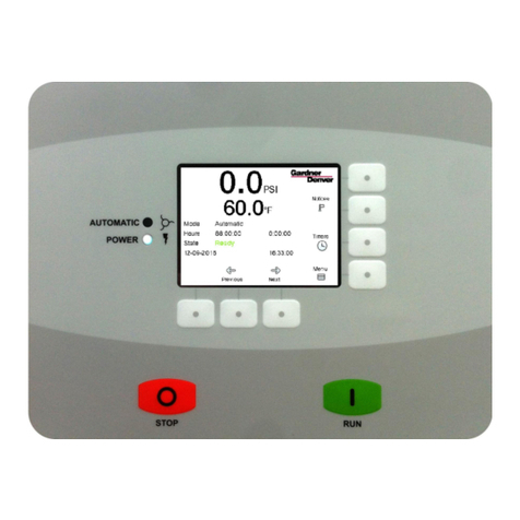
The display is the primary component that the user interacts with. On the front of the display, there is a
color touchscreen interface. The Start and Stop touch buttons are located directly below the screen. The
display houses the processor and memory for the system and interfaces with the other components through
communications ports on the back side.
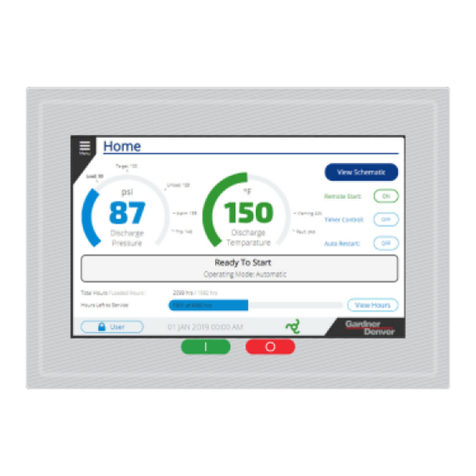
Figure 1: Home Screen Display
The display is shown above in Figure 1 with the Home screen visible. Note that the Start and Stop buttons
as shown in the image are active areas of the touchscreen rather than physical push-buttons.

13-17-621 Page 10
2.1.2 IO Module
The IO module is mounted inside the compressor control cabinet and connects to the display via RS485
communications and houses all of the terminations for the analog and digital input and output signals. These
values are monitored and controlled by the display to operate the compressor. The IO module also contains
RS485 communications ports for customer connection and sequencing with multiple machines.
Figure 2: IO Module
The IO module is shown in Figure 2 above. Note that depending on the type of compressor you have, your
IO module may have more or less inputs and outputs present on it, indicated by the amount and size of
connectors on the board.

13-17-621 Page 11
2.1.3 Cellular Module
The Governor™ controller features a cellular module that is connected to the display by USB. This connects
into the iConn by Gardner Denver™ platform to provide machine health monitoring and analysis.
Figure 3: Cellular Module
The cellular module is shown in Figure 3 above. It is mounted in the control cabinet on DIN rail and
connected to an antenna mounted on the top of the compressor package.
2.2 Features and Method of Control
The Governor™ controller is responsible for safe operation of the compressor package and is optimized for
the customer based on their machine specifications. The Governor™ controller utilizes Gardner Denver’s
heritage of compressor package design and operation to intelligently determine when the machine is
operating normally and when it needs attention. System inputs, such as pressure and temperature, are
monitored individually and collectively to check for a variety of different system conditions.
When running the machine, the controller ensures that the customer’s pressure requirements are
maintained. After configuring and enabling the controller, all operation is automatic. The controller can be
set up to start / stop on a schedule and use two different pressure bands to more efficiently meet system
demand. Programmable inputs and outputs are available to interface to an array of external equipment.
Modbus and remote interfaces are provided to monitor the machine.
2.3 Hardware Specs
2.3.1 Display Module
The display is a customized module, designed and developed for Gardner Denver. Figure 4: Oblique
View & Figure 5: Rear View below shows the Oblique and Rear View of Display Module.

13-17-621 Page 12
Figure 4: Oblique View
Figure 5: Rear View

13-17-621 Page 13
2.3.1.1 Technical Data:
Table 1 below details the technical data of the display module.
Table 1: Display Module
Technical Data
General Information
Cooling
Passive
Reset button
Yes
Status Indicators
Supply voltage OK, operating state, module status, Ethernet, CAN
Rx/Tx, RS485 Rx/Tx
Certification
UL
Interface
Interface IF1
Type
USB 2.0
Variant
Type A
Current Carrying Capacity
0.49 A
Interface IF2
Type
USB 2.0
Variant
Type A
Current Carrying Capacity
0.49 A
Interface IF3
Type
Ethernet
Variant
1XRJ45 Shielded
Line Length
Max. 100 m between 2 nodes (segment length)
Max. Transfer Rate
10/100 Mbit/s
Interface IF4
Type
CAN bus
Variant
3 pins of the 6-pin multipoint connector
Bus terminating resistor
120 Ω, can be switched using software
Max. distance
1000 m
Interface IF5
Type
RS485
Variant
3 pins of the 6-pin multipoint connector
Max. Distance
1200 m
Transfer rate
Max 115.2 kbit/s
Display
Type
TFT color
Diagonal
7.0”
Colors
16.7 million (RGB, 8 bits per channel)
Resolution
WVGA, 800 x 480 pixels
Contrast
Typ. 600:1
Viewing Angles
Horizontal
Direction L / Direction R = Typ. 70°
Vertical
Direction U / Direction D = Typ. 60°
Backlight
Type
LED
Brightness
Typ. 500 cd/m²
Touch screen
Type
AMT
Technology
Analog resistive
Electrical Characteristic
Nominal voltage
24 VDC -15% / +20%
Power consumption
Typ. 6 W / Max. 12.5 W
Reverse polarity protection
Yes
Electrical isolation
Ethernet (IF3) to other interfaces and to device

13-17-621 Page 14
Operating conditions
Installation elevation above sea level
0 to 2000 m
No limitation
>2000 m
Reduction of ambient temperature by 0.5°C per 100 m
Ambient Conditions
Temperature
Operation
-20 to 60°C
Storage
-25 to 70°C
Transport
-25 to 70°C
Relative humidity
5 to 95%, non-condensing
Mechanical Properties
Front
Keypad overlay
Material
Polyester
Design
Customized
Dimensions
Width
197 mm
Height
140 mm
Depth
47.8 mm
weight
0.6 kg
2.3.1.2 Diagnostics LEDs:
The diagnostic LEDs are located on the back of the Power Panel. Figure 6 below displays the diagnostic
LEDs available on the Display Module.
Figure 6: LEDs in Display Module
Table 2 below explains the LEDs and their Color Codes.
Table 2: Display Module LED Diagnostic
LED STATUS
LED
Color
Status
Description
RDY/F
Yellow
On
Mode BOOT, SERVICE or DIAGNOSIS
Blinking
LED "R/E" blinks red and LED "RDY/F" blinks yellow, when there is a
license violation.
R/E
Green
On
Mode RUN: The application is running.
Red
On
Mode BOOT, SERVICE or DIAGNOSIS
Blinking
LED "R/E" blinks red and LED "RDY/F" blinks yellow when there is a
license violation.
CAN (IF4)
Yellow
On
Data is transmitted via CAN bus interface IF4.
TERM (IF4)
Yellow
On
The integrated terminating resistor for the CAN bus interface (IF4) is
switched on.
RS485 (IF5)
Yellow
On
Data is transmitted via CAN bus interface IF6.
TERM (IF5)
Yellow
On
The integrated terminating resistor for the RS485 bus interface (IF5) is
turned on.

13-17-621 Page 15
2.3.1.3 Reset Button / Operating Modes:
The Reset button is reserved for system operations such as setting the system into different boot modes.
Do not use the reset button unless directed by Gardner Denver Service. Location of reset button is shown
just for reference purpose below in Figure 7.
Figure 7: Reset Button
2.3.1.4 Connection Elements:
Below are the electrical connections available on the display unit in the Figure 8.
Figure 8: Connection Elements
CAN bus and RS485 Interface:
Figure 9 below shows the CAN bus and RS485 interface and Table 3 lists its pinouts.
Figure 9: CAN bus and RS485

13-17-621 Page 16
Table 3: CAN bus and RS485
CAN BUS CONNECTION
Terminal
Assignment
Interface
Function
1
CAN_H
IF4
CAN High
2
GND
Ground
3
CAN_L
CAN Low
4
DATA
IF5
Data
5
GND
Ground
6
DATA\
Data inverted
Ethernet Interface
Figure 10 below shows the Ethernet Interface and
Figure 10: Ethernet Interface
Table 4 lists the Ethernet pinouts and signal diagnostics of the Ethernet port LEDs.
Table 4: Ethernet Interface and LED Diagnostics
ETHERNET CONNECTION
Terminal
Assignment
Explanation
1
RXD
Receive Signal
2
RXD\
Received signal inverted
3
TXD
Transmit signal
4
Termination
Termination
5
Termination
Termination
6
TXD\
Transmit signal inverted
7
Termination
Termination
8
Termination
Termination
Diagnostic LED
LED
Color
Status
Description
LNK
Green
On
The link to the remote station is established
ACT
Orange
On
No Ethernet activity is taking place on the bus
Blinking
The link to the remote station is established and Ethernet activity it
taking place on the bus.
USB Interface:
The Power Panel is equipped with a USB 2.0 host controller with 2 USB interfaces. Figure 11 shows the
USB interface and Table 5 list the USB data transfer rate and Power Supply.
Figure 11: USB Interface

13-17-621 Page 17
Table 5: USB
USB Interface
Transfer Rate
Low speed (1.5 MB/s), Full Speed (12 MB/s), High Speed (480 MB/s)
Power Supply
Max. 0.49 A per interface
Power Supply:
Figure 12: Power Supply interface
The Pinout for the power supply is listed Table 6 and printed on the back of the Power Panel. The Power
Panel has reverse polarity protection that prevents the supply voltage from being connected incorrectly and
damaging the device. Figure 12 above shows the Power Supply interface.
Table 6: Power Supply
Power Supply
Terminal
Assignment
Explanation
1
+
24 VDC
2
-
GND
2.3.2 IO Module:
Gardner Denver uses a series of IO modules based on machine configuration.
2.3.2.1 Technical Data:
In the Table 7 below the technical data of the IO module is listed.
Table 7: IO Module
Technical Data
Model Number
TEN014983
TEN014982
TEN014980
TEN014981
Short description
I/O Module
digital inputs, 6
analog inputs, 12
digital outputs,
2 analog outputs, 9
PT1000/PTC, 1
PWM output
8 digital inputs, 6
analog inputs, 8
digital outputs,
1 analog output, 9
PT1000/PTC, 1
PWM output
8 digital inputs, 4
analog inputs, 12
digital outputs,
2 analog outputs, 6
PT1000/PTC, 1
PWM output
8 digital inputs, 3
analog inputs, 8
digital outputs, 4
PT1000/PTC, 1
PWM output
Interface
1x CAN bus, 2x
RS485
1x CAN bus, 1x
RS485
1x CAN bus, 2x
RS485
1x CAN bus, 1x
RS485
General Information
Cooling
Passive
LEDs
Quantities
5
4
Status
Operating state, module status, RS485, CAN bus
Certification
UL

13-17-621 Page 18
Input I/O Power Supply
Connection
designation
X07, X08, X09
X07, X08
X07, X08, X09
X07, X08
Input voltage
24 VDC -25%/+30%
Fuse
Required line fuse: Max. 10 A, slow-blow
Interfaces
Interface IF2
Conn designation
X02 RS485
Signal
RS485
Max. distance
1200 m
Transfer rate
Max. 115.2 kbit/s
Interface IF3
Conn designation
X03 RS485
-
X03 RS485
-
Signal
RS485
-
RS485
-
Max. distance
1200 m
-
1200 m
-
Transfer rate
Max. 115.2 kbit/s
-
Max. 115.2 kbit/s
-
Interface IF4
Conn designation
X0 CAN I/O
Signal
CAN bus
Max. distance
1000 m
Transfer rate
500.0 kbit/s
Digital Inputs
Quantity
8
Conn designation
X05, X06
Nominal voltage
24 VDC
Analog Inputs
Quantity
6
4
3
Conn designation
X11
Input
4 to 20 mA, 2-wire connections
Resistance measurement temperature inputs
Quantity
8X PT1000, 1X PTC
4X PT1000, 2X
PTC
2X PT1000, 2X
PTC
Conn designation
X12, X13
Input
Resistance measurement for 2-wire connections
Digital Output
Quantity
12
8
12
8
Conn Designation
X07, X08, X09
X07, X08
X07, X08, X09
X07, X08
Nominal Voltage
24 VDC
PWM Output
Quantity
1
Conn designation
X08
Nominal voltage
24 VDC -25%/+30%
Analog Output
Quantity
2
1
2
1
Conn designation
X10
Nominal voltage
4 to 20 mA with 2-wire connections
Power Supply
Conn designation
X01
Voltage range
24 VDC -5%/+30%
Power
consumption
7 W
6.5 W
5.6 W
4.3W
Operating conditions
Mounting orientation
Horizontal
Yes
Vertical
Yes
Installation elevation above sea level
0 to 2000 m
No limitation
>2000 m
Reduction of ambient temperature by 0.5°C per 100 m
maximum
4500 m
Ambient Conditions

13-17-621 Page 19
Temperature
Operation
-10 to 60°C
Storage
-20 to 70°C
Transport
-20 to 70°C
Relative humidity
Operation
5 to 95%, non-condensing
Storage
5 to 95%, non-condensing
Transport
5 to 95%, non-condensing
Mechanical Properties
Dimensions
Width
190 mm
Height
198 mm
Depth
31 mm
2.3.2.2 Wiring:
Unshielded Lines:
All unshielded lines must be relieved of tension by using a cable tie to secure to the grounding
plate.
Shielded Lines:
A central ground connection is available to effectively deflect interference. All cable shields must
by connected to ground with good conductivity using a cable tie on the grounding plate or some
other method.
Grounding:
The connection to ground potential must be as short as possible and sufficiently strong (≥4 mm²).
Figure 13 explains the wiring diagram for the IO module. The following should be considered when wiring:
1) Good Conductive connection to the metallic and grounded rear panel.
2) Connect the braided shield wrapped with conductive foil to the grounding plate using cable ties.
Figure 13: IO Module Wiring

13-17-621 Page 20
2.3.2.3 Status LED:
Figure 14: IO Module LED Status and Diagnostics
2.3.2.4 Connection Interface:
Power Supply (X01)
Figure 15 and Table 8 below shows the connector (GD Part TEN014969) used for power supply
connections and pinout to signal details.
Figure 15: Power Supply (X01)
Table 8: Power Supply (X01)
Power Supply
Pin
Signal
1
+24 VDC
2
GND
RS485 Interface (X02)
Only shielded cable must be used. Figure 16 below shows the connector (GD part TEN014970) used for
RS485 connection and Table 9 for connector pin number to signal details.
Figure 16: RS485 Interface (X02)
This manual suits for next models
3
Table of contents
Other Gardner Denver Controllers manuals

Gardner Denver
Gardner Denver AIRSMART User manual

Gardner Denver
Gardner Denver AirSmart VS25A Service manual

Gardner Denver
Gardner Denver GD PILOT TS Series Quick guide

Gardner Denver
Gardner Denver AirSmart G2 Service manual

Gardner Denver
Gardner Denver AUTO SENTRY RS2000 Service manual

Gardner Denver
Gardner Denver GD Connect 12 User manual

Gardner Denver
Gardner Denver Welch VCpro 600 Series User manual

Gardner Denver
Gardner Denver Governor User manual

Gardner Denver
Gardner Denver AIRSMART User manual

Gardner Denver
Gardner Denver DELCOS 3100 User manual