manuals.online logo
Brands
  1. Home
  2. •
  3. Brands
  4. •
  5. LAE
  6. •
  7. Controllers
  8. •
  9. LAE SMD34RU User manual

LAE SMD34RU User manual

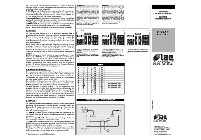
We thank you for choosing an LAE controller. Before proceeding to the installation, please read this instructions sheet carefully; only in this way you will obtain
maximum performances and safety.
1. INSTALLATION
1.1 The SMD90 must be secured to the panel by means of screws or rivets to be inserted into the appropriate slots. Protection is IP30, therefore please locate
the unit in a position ensuring that no liquid infiltrates and damages the board.
1.2 Probes, power supply and outputs must be connected strictly according to the indications appearing on the board; the cables can pass through the hole
on the unit side. For supply voltage and maximum switchable loads, please read the label on the enclosure.
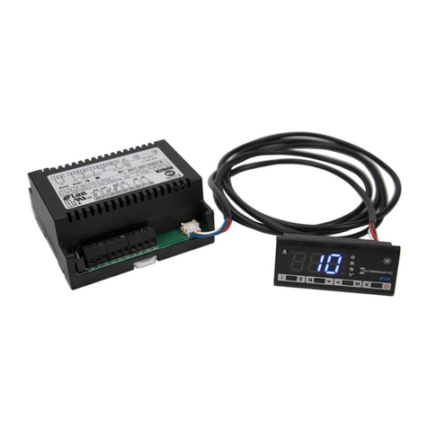
The flat cable of the SMD34RU remote unit must be connected to the relevant connector, please make sure that the mechanical polarity is respected.
1.3 The front of the SMD34RU must be inserted into the panel and sandwiched with the backside cover, then finally firmly closed by means of the screws
provided with the enclosure.
1.4 Probe T1 measures the air temperature and is used for the thermostat function. Probe T2 measures the evaporator temperature and must be secured to it
in a place where the maximum frost growth occurs.
1.5 The unit works with an ambient temperature between -10°.. +50°C and 15%.. 80% relative humidity. To reduce the effects of electro-magnetic interference,
place the probe and signal cables as away as possible from power lines.
Caution: where delicate or valuable products have to be maintained under strict conditions, please use a different controller for limit and alarm functions.
2. OPERATING LEVELS
For 3 seconds from the power-up the display illuminates a dash (self-check phase). The following indications depend on the operating status of the controller and
from the menu level activated by the operator.
On table 1 you can see status, levels and indications relevant to them.
2.1 S
TANDBY
:OFF permanently displayed to show the standby status. Setting the parameter OFF=YES enables the [0/I] button that allows to put the SMD90
on standby. If OFF=NO the button [0/I] is inhibited.
On standby, output controls and buttons are excluded with the exception of light command (manually or door controlled).
2.2 N
ORMAL
:during the normal operation phases, the display shows the air temperature, however the following indications can come up: ERR probe T1 fault;
ALR alarm status; DEF defrost in progress.
2.3 I
NFO MENU
:pressing button enables the information selection menu. In this menu the instantaneous temperatures T1, T2 and the alarm status appear.
It’s also possible to start a defrost manually or set the setup access code. The selection of the data to be displayed can take place sequentially, by repeatedly
pressing , or quickly via buttons and to scroll through the menu. You exit from the menu by pressing button or automatically after 5 seconds of no
button activation.
2.4 S
ETUP
:you have got access to the parameter menu by selecting 47 as passcode PC. To achieve this press buttons and or . The exit from the
setup takes place by pressing button or after 30 seconds of no button activation.
3. CONTROL PARAMETERS
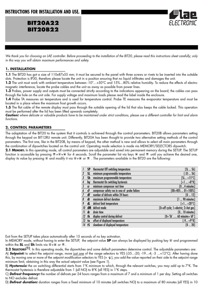
The adaptation of the controller to the system that it controls is achieved through the parameters in the setup. The available parameters appear on table 2
hereinafter. You proceed from one parameter to the next/previous by pressing button or . To display the related value, press button , to change it press
INSTRUCTIONS FOR INSTALLATION AND USE.
SMD90B35 (A-C)
SMD34RU
S
TANDBY
N
ORMAL
I
NFO MENU
I
NFO DATA
S
ETUP
P
ARAMETER
MENU VALUE
OFF -20 DF DF- ADR 255
air temperature
manual defrost waiting for peripheral
start sequence address
DEF AL A H --- ---
defrost on alarm sources high ….
temperature
ALR T1 -18 --- ---
new alarm shows air ….
temperature
ERR T2 -22 SPH -18
probe 1 failure shows coil maximum
temperature setpoint
PC 47 SPL -25
pass code minimum
setting setpoint
Table 1
button and at the same time or . The exit from the setup takes place automatically after 30 seconds of no button activation or immediately by pressing
button .
The setpoint SP can be displayed and set also during the normal operation status with and or buttons. The setting range however remains within the
limits established with SPL and SPH.
Table 2
4. DISPLAYS
The temperatures measured by probes T1 and T2 are treated by the microprocessor in such a way as to display them in the most meaningful way. To achieve
this, the temperatures can then be corrected by the respective offsets OS1 and OS2 and displayed in degrees Celsius or Fahrenheit, depending on the value
set to SCL.
Caution: if you change the readout scale you must then IMPERATIVELYre-configure the parameters relating to the absolute temperatures (SP, DLI, FDR …) and
to the differential temperatures (HYS, ATL, ATH …).
The air temperature, offset by OS1, before being displayed is treated by a special algorithm allowing the simulation of a thermal mass directly propotional to
the value set to SIM. The resulting effect is a hunting reduction on the displayed value.
By setting DDY to values greater than 0, during defrost, instead of the temperature, the display shows DEF, which will remain beyond defrost end for the number
of programmed minutes.
5. THERMOSTAT FUNCTION
5.1 Temperature control is based upon the comparison between temperature T1, the setpoint SP and the hysteresis HYS. The thermostat operation is
determined by the value set to HYS: if greater than 0 there will be COOLING control, if lower than 0 there will be HEATING control, if equal to 0, the thermostat
will be excluded and the corresponding output will be switched off permanently.
Example 1: HYS 02, SP -20; relay Off with T1 -20° and On with T1 -18°.
Example 2: HYS –04, SP 70; relay Off with T1 +70° and On with T1 +66°.
The actual relay on switching is however only possible if since the off switching the minimum rest time CRT has elapsed.
The relay status is signalled by the relevant dot on the display.
5.2 In consequence to failure of probe T1, the display shows ERR and the output is controlled with a fixed time established by CDC. This determines the output
running time within 10 minute cycles.
Example: CDC 06, 6 minutes On, 4 minutes Off.
6. DEFROST
6.1 Defrost automatically starts every time the built-in timer matches the time necessary to obtain the defrost frequency determined with DFR. For example,
with DFR=4 there will be a defrost every 6 hours. With DFR set to 0, the timed defrost function is excluded.
Defrost can be started manually from the Info menu in the following way: select DF, press button first then simultaneously.
The built-in timer is set to zero every time the unit is switched on (power supply or standby) and every time defrost is started.
6.2 Once that defrost has been started, the outputs are controlled by the parameter DTY according to the following table:
6.3 Defrost terminates either when time DTO elapses or, if the evaporator probe is active (T2=YES), when temperature DLI is measured.
Now, if DRN is greater than 0, before cooling starts, all the outputs remain off for the time set to DRN. This phase, called drain down, will allow a complete
ice melting and the drain of the resulting water.
INSTRUCTIONS FOR INSTALLATION AND USE.
SPL -40.. SPH [°] minimum temp. set ATD 0.. 120 [min] temperature alarm delay
SPH SPL.. +250 [°] maximum temp. set ADD 0.. 120 [min] door alarm delay
SP SPL.. SPH [°] actual temperature set ACL 0.. 120 [weeks] condenser clean interval
HYS -30.. 0.. +30 [°] thermostat hysteresis CRT 0.. 30 [min] compressor rest time
DFR 0.. 24 defrost frequency/24h CDC 0.. 10 compressor duty cycle
DLI 0.. +70 [°] defrost end temperature OFF YES/NO standby key enable
DTO 1.. 120 [min] defrost timeout DS YES/NO door switch enable
DTY OFF/ELE/GAS defrost type LDC YES/NO door switched light
DRN 0.. 30 [min] drain down T2 YES/NO probe 2 enable
DDY 0.. 60 [min] defrost display control SCL °C/°F display scale
FRC 0.. 5 fan run control OS1 -15.. +15 [°] probe 1 offset
FDR -40.. +70 [°] fan re-start temperature OS2 -15.. +15 [°] probe 2 offset
ATL -25.. 0 [°] low alarm differential SIM 0.. 100 display slowdown
ATH 0.. +25 [°] high alarm differential ADR 0.. 255 address
DTY DEFROST COMPRESSOR FANS
OFF off off on
ELE on off off
GAS on on off
The defrost relay status is signalled by illuminating the relevant dot on the display.
7. EVAPORATOR FAN CONTROL
7.1 During temperature control, the fans are controlled by FRC. If FRC=0 the fans run continuously, if it’s greater than 0, then the fans cycle according to the
compressor. Both are switched on simultaneously but the fan run continues for a time proportionate to the compressor run and the FRC parameter. One unit of
FRC corresponds to 20% of the compressor run. For instance, with FRC=2 compressor and fans start simultaneously and, if the compressor runs for 6 minutes,
then the fans are on for 6+2 minutes and 24 seconds (40% of 6 minutes).
7.2 If the SMD is connected to a door switch, you must set the parameter DS to YES to obtain an evaporator fan control according to door opening. This
control takes place during temperature control only.
7.3 After defrost, if probe T2 is active (T2=YES) temperature FDR provides fan re-start. In other words, the fans re-start when the evaporator has a temperature
lower than FDR. If this condition is not met within 3 minutes following defrost termination, the fans will however re-start.
The relay status is signalled by the relevant dot on the display.
8. ALARMS
The SMD90 allows a check on the correct operation of the thermostat, on the door being left open and on the periodic condenser clean warning, in addition
to the functional alarms because of power failure and fault of probes T1 or T2. When an alarm takes place, the controller switches on the relevant relay and
buzzer, shows the anomaly by flashing the relevant LED and ALR on the display. Hereinafter we report how the unit works according to the alarm sources.
8.1 ATL determines the alarm differential for temperatures lower than setpoint (cooling) or setpoint + hysteresis (heating) and ATH is the alarm differential for
temperatures higher than setpoint (heating) or setpoint + hysteresis (cooling).
Example 1: SP= -20, HYS= 02, ATL= -05, ATH= 05;
the alarm thresholds are set to –25° and –13°.
Example 2: SP= 70, HYS= -04, ATL= -05, ATH= 05;
the alarm thresholds are set to +61° and +75°.
The temperature alarm warning can be immediate or delayed by the time ATD if it’s greater than 0. By setting to 0 one or both differentials, the corresponding
alarm is excluded.
During defrost, the high temperature alarm is excluded.
8.2 By enabling door switch control, DS=YES, the relevant door alarm function is also enabled. Therefore, as described in 7.2, when the door is opened the
fans will be stopped immediately and, after the delay ADD, the compressor will be stopped too and the alarm will be signalled.
8.3 By setting parameter ACL to a value greater than 0 you enable the periodic condenser clean warning. This means that, when the timer counting the
thermostat running time matches the weeks programmed with ACL, the display will show a condenser clean request.
Example: with ACL=16 you will obtain a warning every 16x7x24=2688 hours of compressor operation. In other words supposing that the compressor
runs 5 minutes and rests for 5 minutes, there will be a warning after about 32 weeks.
To reset the timer, enter info menu and get to the display of the indication related to the condenser clean - A C – then press buttons and simultaneously.
8.4 In case of a new alarm, pressing button removes the indication ALR permanently, mutes the buzzer and by pressing button again shows the alarm
cause. The indications on the display are:
A H high temperature; A L low temperature; A D opened door; A C condenser clean; A 1 probe T1 fault; A 2 probe T2 fault; A – no alarm.
By pressing button , the buzzer is muted, after that, if the alarm persists, it’s periodically switched on for 20 seconds every hour until the alarm is over. This
applies to all alarms with the exception of the condenser clean warning.
The alarm LED and relay, on the contrary, remain on as long as the alarm persists.
9. LIGHT SWITCH AND SERIAL COMMUNICATION
9.1 The relay controlling the lights can alternatively be controlled manually by means of button or, if the switch is fitted, automatically when the door is
opened. In this case the parameters DS and LDC must both be set to YES. As described at 2.1 the light function is independent from standby.
9.2 The SMD90 can be fitted with RS485 serial port allowing the controller to exchange information with supervisory softwares like the TAB. The data base
puts all measurement and control data of the controller on line. The identification of every single unit within the network is given by parameter ADR.
WARRANTY
LAE electronic Srl warrant that their products are free of any defects in workmanship and materials for a period of 1 (one) year from date of production
shown on the enclosure. LAE electronic Srl shall only repair or replace those products of which defects are due to LAE electronic Srl and recognised by their
technicians. LAE electronic Srl are not liable for damages resulting from malfunctions of the products.
Defects due to exceptional operating conditions, misapplication and/or tampering will void the warranty.
All transport charges for returning the product to the manufacturer, after prior authorisation by LAE electronic Srl, and for the return to the purchaser are
always for the account of the purchaser.
INSTRUCTIONS FOR INSTALLATION AND USE.
VIA PADOVA, 25
31046 ODERZO /TV /ITALY
TEL. 0422 815320 - 815303
TELEFAX 0422 814073
www.lae-electronic.com
E-mail: [email protected]
PARTNER VENEZIA • 041 5460713
INSTRUCTIONS FOR INSTALLATION AND USE.
SMD90B35E-C
T
ERMINAL
F
UNCTION
R
ATINGS
T
ERMINAL
F
UNCTION
R
ATINGS
L-N Power supply 230 Vac;50/60Hz L3, L4 Auxiliary loads 8(3)A; 230 Vac
L1, L2 Compressor 20(6) A; 230 Vac L9, L10 Defrost 8(3)A; 230 Vac
L5, L6 Evap. Fans 8(3)A; 230 Vac A1-A2 Alarm 8(3)A; 230 Vac
A3
L7 Indoor lights 8(3)A; 230 Vac
WIRING DIAGRAM

This manual suits for next models

1

Other LAE Controllers manuals

LAE LDU15 User manual

LAE

LAE LDU15 User manual

LAE BIT20 Series User manual

LAE

LAE BIT20 Series User manual

LAE BIT20A22 User manual

LAE

LAE BIT20A22 User manual

LAE AC1-2W Series User manual

LAE

LAE AC1-2W Series User manual

LAE AT1-5 User manual

LAE

LAE AT1-5 User manual

LAE MS27 User manual

LAE

LAE MS27 User manual

LAE AC1 -2W Series User manual

LAE

LAE AC1 -2W Series User manual

LAE AD3-5 Series User manual

LAE

LAE AD3-5 Series User manual

LAE AR2-27 User manual

LAE

LAE AR2-27 User manual

LAE BR1-28 User manual

LAE

LAE BR1-28 User manual

LAE BR1-28 User manual

LAE

LAE BR1-28 User manual

LAE LTR-5 Series User manual

LAE

LAE LTR-5 Series User manual

LAE AC1-27 Series User manual

LAE

LAE AC1-27 Series User manual

LAE BR1-27 User manual

LAE

LAE BR1-27 User manual

LAE LCD15 User manual

LAE

LAE LCD15 User manual

LAE RDC122T1R2 User manual

LAE

LAE RDC122T1R2 User manual

Popular Controllers manuals by other brands

Mode Lighting ColourStyle user guide

Mode Lighting

Mode Lighting ColourStyle user guide

Distech Controls VA-024ZS Series Hardware installation guide

Distech Controls

Distech Controls VA-024ZS Series Hardware installation guide

turck TX700 HMI/PLC Series quick start guide

turck

turck TX700 HMI/PLC Series quick start guide

Servotronix softMC 3 installation guide

Servotronix

Servotronix softMC 3 installation guide

Helios 5 Target quick start guide

Helios

Helios 5 Target quick start guide

Honeywell EVOTOUCH CONTROLLER user guide

Honeywell

Honeywell EVOTOUCH CONTROLLER user guide

Ascon tecnologic TLK 33 operating instructions

Ascon tecnologic

Ascon tecnologic TLK 33 operating instructions

Faderfox micromodul PC4 user manual

Faderfox

Faderfox micromodul PC4 user manual

Epson S1D13700 manual

Epson

Epson S1D13700 manual

Intellitec TOUCHLITE installation instructions

Intellitec

Intellitec TOUCHLITE installation instructions

DeZurik MO manual

DeZurik

DeZurik MO manual

Omron NJ501-1300 user manual

Omron

Omron NJ501-1300 user manual

SAJ PDS51 user manual

SAJ

SAJ PDS51 user manual

Chamberlain Security+ 974-315CB Owner's instructions

Chamberlain

Chamberlain Security+ 974-315CB Owner's instructions

RESEARCH CONCEPTS RC2000C manual

RESEARCH CONCEPTS

RESEARCH CONCEPTS RC2000C manual

Conoflow HP300 Instruction and maintenance manual

Conoflow

Conoflow HP300 Instruction and maintenance manual

SIGMAKOKI OptoSigma PGC-04-U manual

SIGMAKOKI

SIGMAKOKI OptoSigma PGC-04-U manual

Danfoss ECL Comfort 310 installation guide

Danfoss

Danfoss ECL Comfort 310 installation guide

manuals.online logo
manuals.online logoBrands
  • About & Mission
  • Contact us
  • Privacy Policy
  • Terms and Conditions

Copyright 2025 Manuals.Online. All Rights Reserved.