Garmin GRF 10 User manual

GRF™10
Garmin® and the Garmin logo are trademarks of Garmin Ltd. or its subsidiaries, registered in the USA and other countries. These trademarks may not be used
without the express permission of Garmin.
El número de registro COFETEL/IFETEL puede ser revisado en el manual a través de la siguiente página de internet.
Installation Instructions ...................2
Instructions d'installation.................7
Istruzioni di installazione ...............13
Installationsanweisungen ..............19
Instrucciones de instalación ..........25
Instruções de instalação................31
Installatie-instructies.....................37
Installationsvejledning...................43
Asennusohjeet ..............................49
Installeringsinstruksjoner...............54
Installationsinstruktioner ...............60
Instrukcja instalacji .......................65
GUID-B42FCBBC-BDA7-4573-AFF2-701A45D8A8DD v2September 2022

GRF™10
Installation Instructions
Installation Preparation
WARNING
See the Important Safety and Product Information guide in the product box for product warnings and other
important information.
CAUTION
To avoid possible personal injury, always wear safety goggles, ear protection, and a dust mask when drilling,
cutting, or sanding.
NOTICE
When drilling or cutting, always check what is on the opposite side of the surface to avoid damaging the vessel.
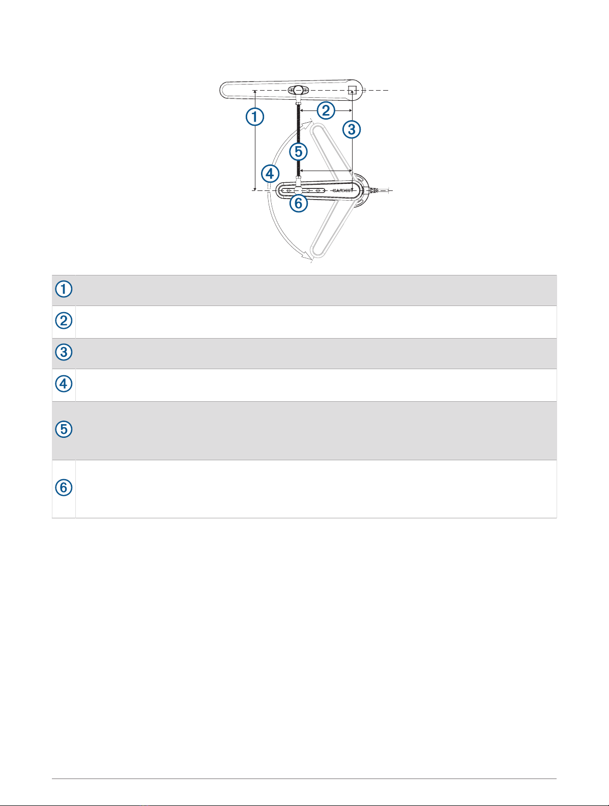
Package Contents
Item Description
GRF™ 10
M4 screw (×5)
M6 locknut (×2)
M6 nut (×2)
Washer
Tiller arm mount
Ball joint assembly (×2)
Threaded rod
2 Installation Instructions
Tools Needed
• Drill and 3.2 mm (1/8 in.) drill bit
• 8 and 10 mm wrenches
• 10 mm socket
• Metal saw appropriate for cutting a threaded rod
• #2 Phillips screwdriver
• Tape measure
• Pencil or marker
• Extension cables, if necessary (Connection Considerations, page4)
Mounting Considerations
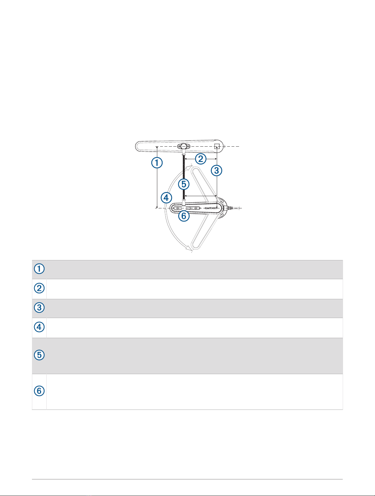
The sensor must be installed parallel to the tiller arm while the rudder is amidships.
The distance from the rotation axis of the tiller to the ball-joint assembly must be the same as the
distance from the rotation axis of the sensor to the ball-joint assembly.
The sensor and rudder rotation axes must be aligned.
The maximum range of travel from stop to stop is 140 degrees (70 degrees from the center position to
each stop). Exceeding this range may cause damage to the sensor.
The rod that connects the sensor to the tiller arm is 300 mm (11.8 in.) long, and can be shortened if
needed.
The rod should be level when connected to the sensor and rudder. If a perfectly level installation is not
possible, the rod must be installed within +/- 5 degrees of level to function correctly.
The rod should be installed perpendicular to the tiller arm and sensor, using the second hole from the tip
of the sensor for the ball-joint connector.
Although the second hole is preferred, the other holes may be used if necessary, based on the installation
location.
Installation Instructions 3

Connection Considerations
• This sensor can be connected to a compatible Garmin® autopilot system with a 12-pin rudder feedback
connector.
• The cable connected to the sensor is 78 in. (2 m) long.
◦If needed, extension cables for the sensor are available from your Garmin dealer.
◦Do not cut the sensor cable to extend or shorten it.
Installation Procedures
Installing the Sensor
For the best results, keep the rudder amidships during the sensor-installation process.
1Rotate the sensor counter-clockwise so the arrows on the back line up in the center .
2Place the sensor at the selected mounting location, and mark the center of the three mounting holes.
3Place the tiller-arm mount on the tiller arm at the mounting location, and mark the center of the two
mounting holes.
4Using a 3.2 mm (1/8 in.) bit, drill three pilot holes in the mounting surface for the sensor, and two pilot holes
in the tiller arm for the tiller-arm mount.
5Fasten one of the ball-joint assemblies to the tiller-arm mount using the included M6 locknut.
6Place the other ball-joint assembly into the appropriate hole on the sensor (typically the second hole from the
tip), and fasten it with the included washer and locknut using a 10 mm socket.
4 Installation Instructions

7Tighten the ball-joint assemblies using an 8 mm wrench at the base.
8Fasten the sensor to the mounting surface using the included screws.
9With the rudder amidships and the sensor at center position, measure the distance from the ball-joint
assembly on the sensor to the location where you plan to attach the tiller-arm mount to the tiller arm.
10 If the threaded rod is too long, cut it to the correct length (Cutting the Threaded Rod, page5).
11 Thread both of the standard M6 nuts onto the threaded rod.
12 Thread the rod into the ball-joint assembly connected to the sensor.
13 Thread the other end of the rod into the ball-joint assembly connected to the tiller-arm mount.
14 Fasten the tiller-arm mount to the tiller using the included screws.
15 Tighten the M6 nuts on the threaded rod against both of the ball-joint assemblies.
Cutting the Threaded Rod
If the included threaded rod is too long for your chosen installation location, you must cut it.
1Thread one of the included standard M6 nuts onto the threaded rod.
Do not use one of the included M6 locknuts.
2Measure and mark the threaded rod with electrical tape.
3Using the appropriate saw, cut the threaded rod at the marked location.
4Remove the nut from the threaded rod, turning it counter-clockwise over the cut area.
The nut should straighten any threads that may have been damaged while cutting the rod.
Connecting the Device to the Autopilot System
1Route the cable from the sensor to the orange 12-pin connector on the ECU of the autopilot system.
The installation instructions provided with your autopilot system will help you identify where this connector is
located.
If needed, extension cables are available.
2Connect the sensor to the autopilot system.
Configuring the Sensor
When connected to a Garmin autopilot system, the sensor is configured using the autopilot helm control or a
connected chartplotter.
NOTE: If an error appears during these steps, the sensor may have reached the limit of its movement range.
Make sure the sensor was installed correctly. If the problem persists, you can bypass this error by moving the
rudder to the farthest position that does not report an error.
1On a helm control or the autopilot screen on a chartplotter, select > Autopilot Setup > Autopilot
Installation Setup > Steering System Setup > Rudder Sensor Setup.
2Position the rudder so the boat would steer fully starboard, and select OK.
3After the starboard calibration is complete, position the rudder so the boat would steer fully port, and select
OK.
4After the port calibration is complete, center the rudder position, let go, and select Begin.
The autopilot takes control of the rudder.
5Wait while the autopilot calibrates the rudder.
6Select an option:
• If the calibration finishes successfully, select OK.
• If the calibration does not finish successfully, repeat this procedure.
Installation Instructions 5

Specifications
Specification Measurement
Dimensions (H×W×D) 215/64 × 2¾ × 717/32 in. (60.8 × 70 × 191.4 mm)
Weight 5.54 oz. (157 g)
Temperature range From 5°F to 158°F (from -15°C to 70°C)
Material Polyoxymethylene (POM), waterproof to IEC 60529 IPX7 standards
Cable length 6½ ft. (2 m)
Max cable extension 49 ft. (15 m)
Up to three 16 ft. 4 in. (5 m) extensions
Nominal input voltage 4.5–5.5 Vdc
Compass-safe distance 1m (3.2ft.)
6 Installation Instructions

GRF™10
Instructions d'installation
Préparation de l'installation
AVERTISSEMENT
Consultez le guide Informations importantes sur le produit et la sécurité inclus dans l'emballage du produit pour
prendre connaissance des avertissements et autres informations importantes sur le produit.
ATTENTION
Pour éviter les blessures, portez des lunettes de protection, un équipement antibruit et un masque anti-
poussière lorsque vous percez, coupez ou poncez.
AVIS
Lorsque vous percez ou coupez, commencez toujours par vérifier ce qui se trouve sur la face opposée de la
surface de montage pour éviter d'endommager le bateau.
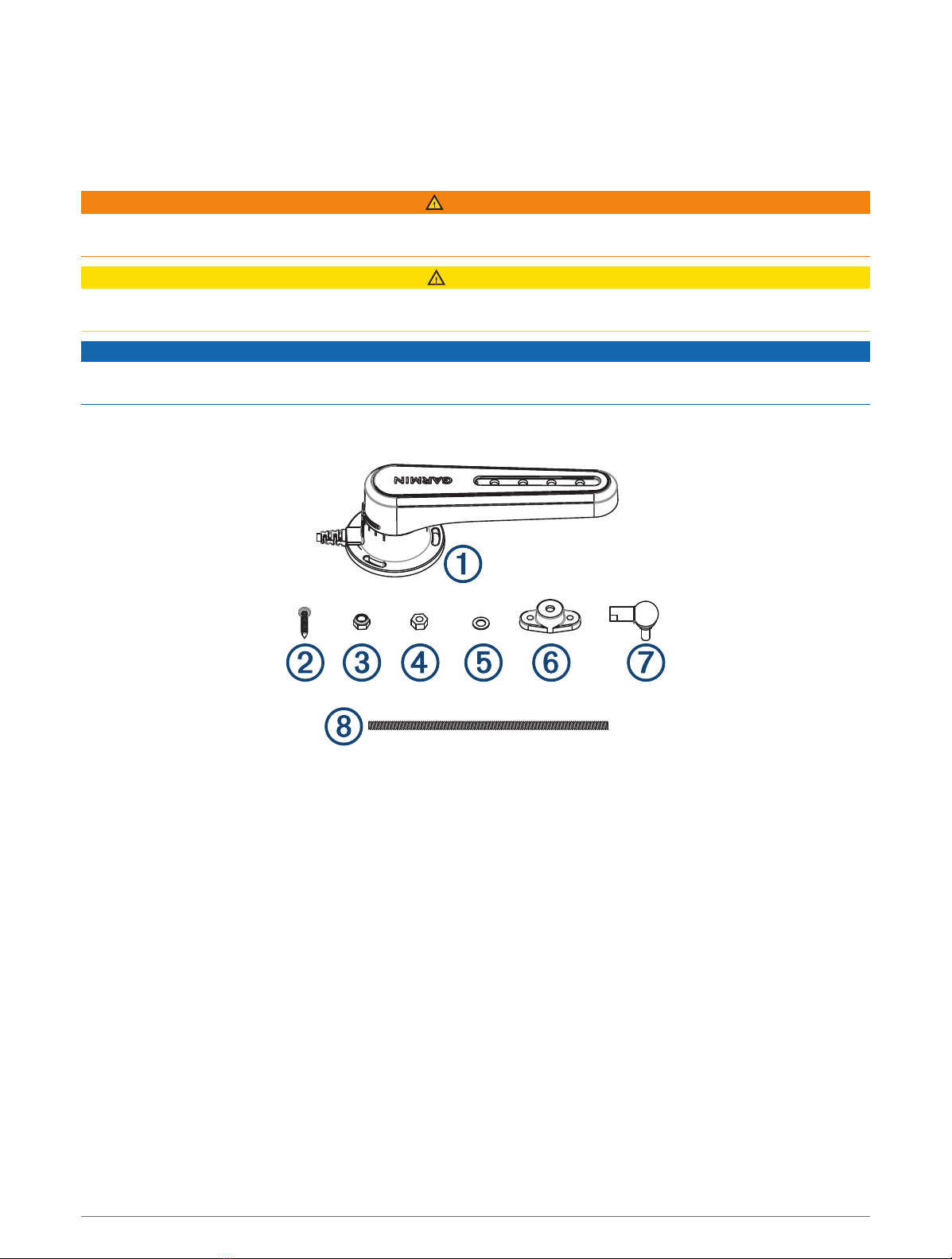
Contenu du pack
Instructions d'installation 7
Élément Description
GRF10
VisM4 (×5)
Contre-écrou M6 (×2)
Ecrou M6 (×2)
Rondelle
Support pour bras de mèche
Assemblage à articulation sphérique (×2)
Tige filetée
Outils requis
• Perceuse et foret de 3,2mm (1/8po)
• Clés de 8 et 10mm
• Douille de 10mm
• Scie à métaux adaptée à la découpe d'une tige filetée
• Tournevis cruciforme numéro2
• Mètre ruban
• Crayon ou marqueur
• Câbles d'extension, si nécessaire (Considérations relatives à la connexion, page9)
8 Instructions d'installation

Considérations relatives au montage
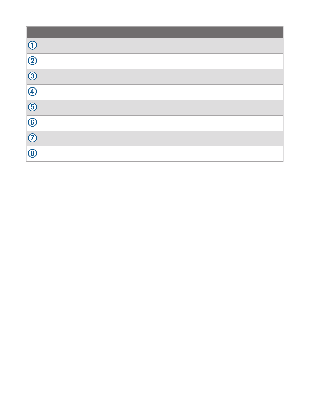
Le capteur doit être installé parallèlement au bras de mèche lorsque la barre est centrée.
La distance entre l'axe de rotation de la mèche et l'assemblage à articulation sphérique doit être égale à
la distance entre l'axe de rotation du capteur et l'assemblage à articulation sphérique.
Les axes de rotation du capteur et de la barre doivent être alignés.
L'angle de course maximal entre les deux butées est de 140degrés (70degrés de la position centrale à
chaque butée). Le dépassement de cette limite risque d'endommager le capteur.
La tige qui connecte le capteur au bras de mèche mesure 300mm (11,8po) de long, et peut être
raccourcie si nécessaire.
La tige doit être au même niveau lorsqu'elle est connectée au capteur et à la barre. Si une installation
parfaitement à niveau est impossible, la tige doit être installée à plus ou moins 5degrés du niveau pour
fonctionner correctement.
La tige doit être installée perpendiculairement au bras de mèche et au capteur, à l'aide du deuxième trou
à partir du bout du capteur pour le connecteur à articulation sphérique.
Bien qu'il soit préférable d'utiliser le deuxième trou, si besoin vous pouvez utiliser les autres trous en
fonction de l'emplacement d'installation.
Considérations relatives à la connexion
• Ce capteur peut être connecté à un système de pilote automatique Garmin compatible équipé d'un
connecteur d'angle de barre à 12broches.
• Le câble connecté au capteur mesure 2mètres (78pouces) de long.
◦Si nécessaire, des câbles d'extension compatibles avec le capteur sont disponibles auprès de votre
revendeur Garmin.
◦Ne coupez pas le câble du capteur pour le raccourcir ou le rallonger.
Instructions d'installation 9

Procédure d'installation
Installation du capteur
Pour des résultats optimaux, maintenez la barre centrée pendant le processus d'installation du capteur.
1Faites pivoter le capteur dans le sens inverse des aiguilles d'une montre pour que les flèches situées à
l'arrière soient alignées au centre .
2Placez le capteur à l'emplacement choisi pour le montage, puis marquez le centre des trois trous de fixation.
3Placez le support pour bras de mèche sur le bras de mèche à l'emplacement de montage, puis marquez le
centre des deux trous de fixation.
4À l'aide d'un foret de 3,2mm (1/8 po), percez trois trous d'implantation dans la surface de montage pour le
capteur, puis deux trous d'implantation dans le bras de mèche destinés au support pour bras de mèche.
5À l'aide du contre-écrouM6 fourni, fixez l'un des assemblages à articulation sphérique au support pour bras
de mèche.
6Placez l'autre assemblage à articulation sphérique dans le trou du capteur approprié (en général, le
deuxième trou à partir du bout), et fixez-le à l'aide de la rondelle et du contre-écrou inclus, en utilisant
une douille de 10mm.
7Serrez les assemblages à articulation sphérique à la base à l'aide d'une clé de 8mm.
8A l'aide des vis fournies, fixez le capteur à la surface de montage.
9En maintenant la barre et le capteur en position centrée, mesurez la distance qui sépare d'un côté
l'assemblage à articulation sphérique situé sur le capteur et de l'autre l'emplacement où vous prévoyez
de fixer le support pour bras de mèche au bras de mèche.
10 Instructions d'installation

10 Si la tige filetée est trop longue, sciez-la pour obtenir la longueur adéquate (Sciage de la tige filetée,
page11).
11 Faites passer les deux écrous M6 standard autour de la tige filetée.
12 Faites passer la tige filetée dans l'assemblage à articulation sphérique connecté au capteur.
13 Faites passer l'autre extrémité de la tige dans l'assemblage à articulation sphérique connecté au support
pour bras de mèche.
14 A l'aide des vis fournies, fixez le support pour bras de mèche au bras de mèche.
15 Serrez les écrous M6 sur la tige filetée contre les deux assemblages à articulation sphérique.
Sciage de la tige filetée
Si la tige filetée est trop longue par rapport à l'emplacement que vous avez choisi pour l'installation, vous devez
la couper.
1Faites passer l'un des écrous M6 standard fournis autour de la tige filetée.
N'utilisez pas l'un des contre-écrous M6 inclus.
2Mesurez et marquez la tige filetée avec du ruban isolant.
3A l'aide de la scie appropriée, découpez la tige filetée à l'emplacement marqué.
4Retirez l'écrou de la tige filetée, en le faisant pivoter dans le sens inverse des aiguilles d'une montre sur la
zone de sciage.
L'écrou devrait redresser le filetage potentiellement endommagé par le sciage de la tige.
Connexion de l'appareil au système de pilote automatique
1Acheminez le câble du capteur vers le connecteur orange à 12broches situé sur l'ECU du système de pilote
automatique.
Les instructions d'installation fournies avec votre système de pilote automatique vous aideront à identifier
l'emplacement de ce connecteur.
Si nécessaire, des câbles d'extension sont disponibles.
2Connectez le capteur au système de pilote automatique.
Configuration du capteur
Lorsqu'il est connecté à un système de pilote automatique Garmin, le capteur est configuré à l'aide du
contrôleur de pilote ou d'un traceur compatible.
REMARQUE: si une erreur se produit au cours de ces étapes, il se peut que le capteur ait atteint sa limite de
portée du mouvement. Vérifiez que le capteur est correctement installé. Si le problème persiste, vous pouvez
annuler cette erreur en déplaçant la barre à la position la plus éloignée ne donnant lieu à aucune erreur.
1Sur un contrôleur de pilote ou sur l'écran du pilote automatique d'un traceur, sélectionnez > Configuration
du pilote automatique > Config. installation pilote auto > Configuration système de navigation > Réglage
capteur d'angle de barre.
2Mettez la barre à tribord pour que le bateau suive cette direction et sélectionnezOK.
3Une fois l'étalonnage tribord terminé, mettez la barre à bâbord pour que le bateau suive cette direction et
sélectionnez OK.
4Une fois l'étalonnage bâbord terminé, ramenez la barre au centre, lâchez tout et sélectionnez Début.
Le pilote automatique prend le contrôle de la barre.
5Patientez pendant que le pilote automatique procède à l'étalonnage de la barre.
6Sélectionner une option:
• Si l'étalonnage réussit, sélectionnez OK.
• Si l'étalonnage ne se termine pas correctement, répétez cette procédure.
Instructions d'installation 11

Caractéristiques techniques
Caractéristique Mesure
Dimensions (H×L×P) 60,8× 70× 191,4mm (215/64× 2¾× 717/32pouces)
Poids 157g (5,54onces)
Plage de températures De -15 à 70°C (de 5 à 158°F)
Matériau Polyoxyméthylène (POM), étanche conformément aux normes
IEC60529IPX7
Longueur du câble 2m (6½pi)
Nombre de rallonges max. 15m (49pieds)
Jusqu'à trois rallonges de 5m (16pieds, 4pouces)
Tension d'entrée nominale 4,5 à 5,5VCC
Distance de sécurité au compas 1m (3,2pi)
12 Instructions d'installation

GRF™10
Istruzioni di installazione
Preparazione all'installazione
AVVERTENZA
Per avvisi sul prodotto e altre informazioni importanti, consultare la guida inclusa nella confezione del
dispositivo.
ATTENZIONE
Per evitare lesioni personali, indossare sempre i visori protettivi, le protezioni acustiche e una mascherina
anti-polvere per trapanare, tagliare o carteggiare.
AVVISO
Prima di effettuare operazioni di trapanatura o taglio, verificare l'eventuale presenza di oggetti sul lato opposto
della superficie da tagliare.
Contenuto della confezione
Istruzioni di installazione 13

Elemento Descrizione
GRF 10
Vite M4 (×5)
Controdado M6 (×2)
Dado M6 (×2)
Distanziale
Supporto per barra
Snodo per barra (×2)
Barra filettata
Strumenti necessari per l'installazione
• Un trapano e una punta da trapano da 3,2mm (1/8poll.)
• Chiavi inglesi da 8 e 10 mm
• Chiave a brugola da 10 mm
• Sega metallica per tagliare la barra filettata
• Cacciavite a croce n. 2
• Metro
• Matita o evidenziatore
• Prolunghe, se necessarie (Note per il collegamento, pagina15)
14 Istruzioni di installazione
Informazioni sull'installazione
Il sensore deve essere installato parallelamente alla barra del timone mentre il timone è a mezza nave.
La distanza tra l'asse di rotazione del timone e il gruppo di snodo sferico deve essere uguale a quella tra
questo e l'asse di rotazione del sensore.
Il sensore e l'asse di rotazione del timone devono essere allineati.
L'intervallo massimo da blocco a blocco è di 140 gradi (70 gradi per lato partendo dal centro alla fine
corsa). Se si supera tale intervallo, il sensore potrebbe danneggiarsi.
Se necessario, la barra filettata da 300 mm (11,8 pollici) che collega il sensore alla barra del timone può
essere accorciata.
La barra filettata deve essere allineata verticalmente al sensore e al timone. Se non è possibile installarla
perfettamente allineata, la si può inclinare al massimo di +/- 5° per un corretto funzionamento.
La barra filettata deve essere installata perpendicolarmente tra il sensore e la barra del timone, usando il
secondo foro a partire dalla fine del sensore del connettore di snodo sferico.
Nonostante sia preferibile utilizzare il secondo foro, all'occorrenza è possibile utilizzare anche uno degli
altri fori in base alla posizione di installazione.
Note per il collegamento
• È possibile collegare il sensore a un sistema di pilota automatico Garmin compatibile dotato di un connettore
dell'angolo di barra del timone a 12 pin.
• Il cavo collegato al sensore ha una lunghezza di 2 m (78 pollici).
◦In caso di necessità è possibile acquistare delle prolunghe presso un qualsiasi punto vendita Garmin.
◦Non tagliare il cavo del sensore per allungarlo o accorciarlo.
Istruzioni di installazione 15

Procedure di installazione
Installazione del sensore
Per ottenere risultati ottimali, mantenere il timone a mezza nave durante il processo di installazione del sensore.
1Ruotare il sensore in senso antiorario in modo che le frecce situate nella parte posteriore vengano
allineate con il centro .
2Collocare il sensore nella posizione desiderata e segnare il centro dei tre fori di montaggio.
3Posizionare il supporto della barra al timone nella posizione di montaggio e segnare il centro dei due fori di
montaggio.
4Utilizzando una punta da 3,2 mm (1/8 pollice), praticare tre fori di riferimento sulla superficie di montaggio e
altri due sulla barra del timone per fissare il relativo supporto.
5Fissare uno degli snodi sferici al supporto della barra sul timone utilizzando il dado di sicurezza M6 in
dotazione.
6Posizionare l'altro gruppo di snodo sferico nell'apposito foro che si trova sul sensore (in genere il secondo
foro a partire dalla punta) e fissarlo con la rondella e il dado di sicurezza in dotazione utilizzando un
manicotto da 10 mm.
7Serrare alla base i gruppi di snodo sferici utilizzando una chiave inglese da 8 mm.
8Fissare il sensore alla superficie di montaggio utilizzando le viti in dotazione.
9Con il timone a mezza nave e il sensore situato nella posizione centrale, misurare la distanza dal gruppo di
snodo sferico sul sensore alla posizione in cui si desidera fissare il supporto alla barra del timone.
16 Istruzioni di installazione

10 Se la barra filettata è troppo lunga tagliarla quanto basta (Tagliare la barra filettata, pagina17).
11 Avvitare entrambi i dadi M6 alla barra filettata.
12 Inserire il perno nel gruppo di snodo sferico collegato al sensore.
13 Inserire l'altra estremità del perno nel gruppo di snodo sferico collegato al supporto della barra del timone.
14 Fissare il supporto per barra al timone utilizzando le viti in dotazione.
15 Serrare i dadi M6 sul perno filettato su entrambi i gruppi di snodo sferici.
Tagliare la barra filettata
Se la barra filettata fornita col sensore è troppo lunga è possibile tagliarla.
1Fissare alla barra filettata uno dei dadi M6 in dotazione.
Non utilizzare uno dei controdadi M6 in dotazione.
2Prendere le misure e segnare con del nastro isolante dove si vuole tagliare la barra filettata.
3Utilizzare una sega adeguata e tagliare la barra filettata nel punto desiderato.
4Rimuovere il dado dalla barra filettata svitandolo verso la parte tagliata.
Il dado dovrebbe regolare i filetti che potrebbero essersi danneggiati durante il taglio della barra.
Collegamento del dispositivo al sistema di pilota automatico
1Instradare il cavo dal sensore al connettore arancione a 12 pin sull'ECU del sistema di pilota automatico.
Fare riferimento alle istruzioni d'installazione del pilota automatico per identificare il connettore corretto.
Se necessario, sono disponibili delle prolunghe.
2Collegare il sensore al sistema di pilota automatico.
Configurazione del sensore
Quando è collegato a un sistema autopilota Garmin, il sensore viene configurato utilizzando il controllo timone
dell'autopilota o un chartplotter collegato.
NOTA: se viene visualizzato un errore durante questa procedura, è possibile che il sensore abbia raggiunto
i punti finali dell'intervallo di movimento. Accertarsi che il sensore sia stato installato correttamente. Se il
problema persiste è possibile ignorare l'errore impostando un limite del timone in una posizione tale da non
richiedere alcuna segnalazione.
1Da una schermata dell'unità di controllo o dalla schermata autopilota su un chartplotter, selezionare >
Impostazione pilota automatico > Setup Timoneria > Impostazione sensore timone.
2Posizionare il timone tutto a dritta e selezionare OK.
3Completata la calibrazione a dritta, posizionare il timone tutto a sinistra e selezionare OK.
4Completata la calibrazione a sinistra centrare il timone e premere Inizio.
Il pilota automatico prende il controllo del timone.
5Attendere che il pilota automatico esegua la calibrazione del timone.
6Selezionare un'opzione:
• Se la calibrazione viene eseguita correttamente, selezionare OK.
• Se la calibrazione non viene eseguita correttamente, ripetere questa procedura.
Istruzioni di installazione 17

Caratteristiche tecniche
Specifica Misure
Dimensioni (A × L × P) 60,8 × 70 × 191,4 mm (215/64 × 2¾ × 717/32 pollici)
Peso 157 g (5,54 once)
Temperatura operativa Da -15 °C a 70 °C (da 5 °F a 158 °F)
Materiale Poliossimetilene (POM), impermeabile in conformità agli standard IEC
60529 IPX7
Lunghezza del cavo 2 m (6½ piedi)
Estensione massima del cavo 15 m (49 piedi)
Fino a tre prolunghe da 5 m (16 piedi e 4 pollici)
Tensione nominale 4,5–5,5 V cc
Distanza di sicurezza dalla bussola 1m (3,2piedi)
18 Istruzioni di installazione
GRF™10
Installationsanweisungen
Installationsvorbereitung
WARNUNG
Lesen Sie alle Produktwarnungen und sonstigen wichtigen Informationen der Anleitung "Wichtige Sicherheits-
und Produktinformationen", die dem Produkt beiliegt.
ACHTUNG
Tragen Sie zum Vermeiden möglicher Personenschäden beim Bohren, Schneiden und Schleifen immer
Schutzbrille, Gehörschutz und eine Staubschutzmaske.
HINWEIS
Prüfen Sie beim Bohren oder Schneiden immer, was sich auf der anderen Seite der Oberfläche befindet, um
Schäden am Boot zu vermeiden.
Lieferumfang
Installationsanweisungen 19

Element Beschreibung
GRF 10
M4-Schrauben (5)
M6-Sicherungsmutter (2)
M6-Mutter (2)
Unterlegscheibe
Tillerarmhalterung
Kugelgelenkeinheit (2)
Gewindestange
Erforderliches Werkzeug
• Bohrmaschine und 3,2-mm-Bohrer (1/8Zoll)
• Schraubenschlüssel, 8mm und 10mm
• Steckschlüssel, 10mm
• Zum Zuschneiden einer Gewindestange geeignete Metallsäge
• Kreuzschlitzschraubendreher Nr.2
• Maßband
• Bleistift oder Stift
• Verlängerungskabel, sofern erforderlich (Hinweise zum Verbinden des Geräts, Seite21)
20 Installationsanweisungen
Other manuals for GRF 10
2
Table of contents
Languages:
Other Garmin Automobile Accessories manuals


Popular Automobile Accessories manuals by other brands


Baumann
Baumann OptiShift Installation and operation manual

BedFin
BedFin BFX Series User's installation guide

Young Electric
Young Electric Sole manual

Whelen Engineering Company
Whelen Engineering Company SAK23 installation guide

Thule
Thule EXPRESSWAY 995 Assembly

Feniex
Feniex GEO Series instruction manual


