Garmin RV-BBT600 Series User manual

RV-BBT600 SERIES
INSTALLATION
INSTRUCTIONS
Important Safety Information
WARNING
See the Important Safety and Product Information guide in the
product box for product warnings and other important
information.
NOTICE
Failure to follow these cautions could result in damage to the
vehicle or poor product performance.
This device must be installed according to these instructions.
Disconnect the vehicle's power supply before beginning to install
this product.
Before applying power to this product, make sure it has been
correctly grounded according to the installation instructions.
You must read all installation instructions before beginning the
installation. If you experience difficulty during the installation,
contact Garmin® Product Support.
Connector Identification
Item Label Connector
Description
Notes
MIC Microphone input 3.5 mm mono miniplug for
the hands-free microphone
(included)
VIDEO IN Video input Composite video RCA
connector
ZONE 1 LINE
OUT
Line out for zone 1 Left, right, and subwoofer
RCA connectors
Item Label Connector
Description
Notes
None Wiring harness
connectors
The wiring harnesses are
not included. See (Pin
Identification, page 1) for
pinout information.
ZONE 2 LINE
OUT
Line out for zone 2 Left, right, and subwoofer
RCA connectors
AUX 1 INPUT Auxiliary input 1 Left and right RCA
connectors
ZONE 3 LINE
OUT
Line out for zone 3 Left, right, and subwoofer
RCA connectors
CAMERA
AUDIO
INPUT/AUX 2
INPUT
Input for camera
audio or for
auxiliary 2
Left and right RCA
connectors
ZONE 4 LINE
OUT
Zone 4 line out Left, right, and subwoofer
RCA connectors
USB (500mA) Reserved for manufacturer
use
Compatible only with low-
current (<500 mA) USB
devices
iPad USB (2.1A) Interfaces and charges
supported smartphones and
USB devices
CAN 1 CAN BUS 1 Connects to an NRX wired
remote control using an
adapter (sold separately)
CAN 2 CAN BUS 2 Reserved for vehicle
integration
N/A AM/FM antenna Connects to the vehicle
antenna. The included
adapter may be required.
Pin Identification
You can use this pinout diagram and table to create a wiring
harness for this device.
Pin Function
Speaker: zone 2 left positive (+)
Speaker: zone 2 left negative (-)
Speaker: zone 1 left positive (+)
Speaker: zone 1 left negative (-)
Speaker: zone 1 right positive (+)
Speaker: zone 1 right negative (-)
Speaker: zone 2 right positive (+)
Speaker: zone 2 right negative (-)
Ignition switch positive (+12 Vdc input)
Power ground (-)
GUID-EFC21AFA-2D40-45E8-8E4C-6A9EFBF01CB9 v4July 2020
Pin Function
Amplifier signal (+12 Vdc output)
Dim
Not applicable
Power input positive (+12 Vdc input)
Backup camera (+12 Vdc to trigger)
Tel/mute (ground to trigger)
Connecting a FUSION® NRX Remote Control
You can connect a FUSION NRX remote control (not included)
to the stereo dock using an adapter cable (not included). You
can purchase an NRX remote control and the required adapter
cable from your FUSION dealer.
You can connect up to three NRX remote controls directly to the
stereo dock without connecting them to an additional power
source. If you want to connect more than three NRX remote
controls to the stereo dock, you must connect them to an
additional power source. See the instructions provided with the
remote control for more information.
1Install each of the NRX remote controls by following the
instructions provided with each remote control.
2Route the network cable from the NRX remote control
network to the location of the stereo dock.
3Connect the adapter cable to the CAN 1 port on the back of
the stereo dock.
4Connect the cable from the NRX remote control network to
the adapter cable.
5Select an option:
• If the NRX remote control network connects to an
additional power source, continue with the dock
installation.
• If the NRX remote control network does not connect to an
additional power source, proceed to the next step.
6Turn on the stereo.
7On the stereo, from the music player, select > Settings >
NRX Power.
When the check box is filled, the dock supplies power and
data to the connected NRX remote controls.
Dock Installation
You must use the included bracket to install the device dock into
a specific vehicle type.
The product package includes the hardware required to attach
the bracket to the dock. The product package does not include
the hardware to attach the bracket to the dashboard or the
dashboard panel.
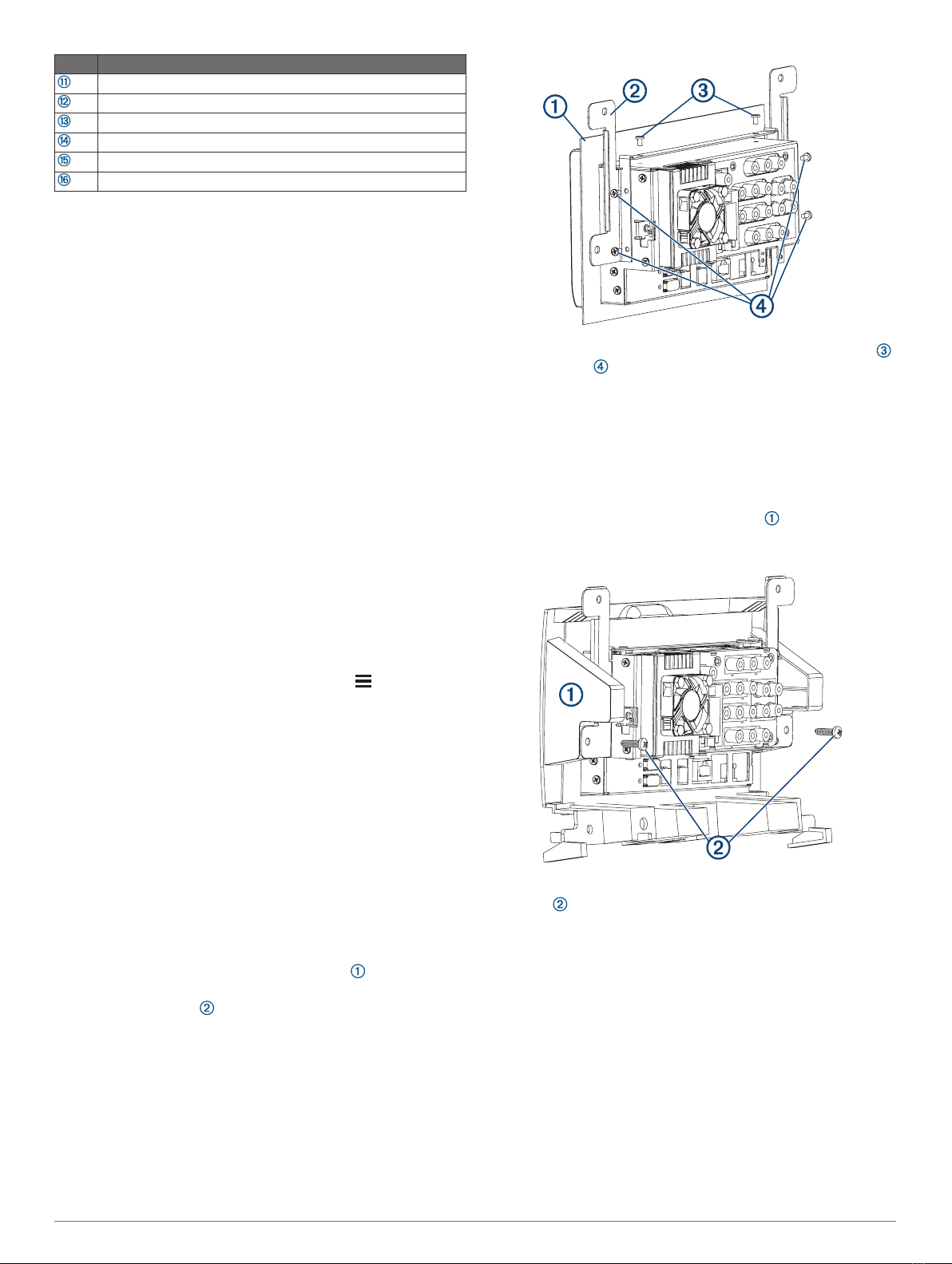
Installing the Bracket on the Dock for Mercedes-Benz®
Sprinter™ Vehicles
You should use the included screws to attach the bracket to the
dock.
1Remove the protective film from the gasket , and slide it
over the dock, with the adhesive facing the front of the dock.
2Place each bracket on the dock, aligning the holes on the
bracket with the holes on the sides and top of the dock.
3Using the included screws, secure each bracket to the top
and the sides of the dock.
Installing the Dock in a Mercedes-Benz Sprinter Dashboard
Before you can install the dock in the dashboard, you must
install the gasket and brackets on the dock.
The product package does not include the hardware required to
fasten the dock bracket to the dashboard or dashboard panel.
1If necessary, remove the dashboard panel or components to
reach the stereo mounting location.
2Place the dock into the dashboard panel , aligning the
upper holes in the bracket with the holes in the dashboard
panel.
3Secure the dock in the dashboard panel using self-tapping
screws through the lower holes in the bracket.
4From inside the dashboard, connect all necessary cables and
wires to the dock.
5Place the dashboard panel in the dashboard, and secure it
using screws through the top and bottom holes.
2
6If necessary, reinstall all remaining dashboard components.
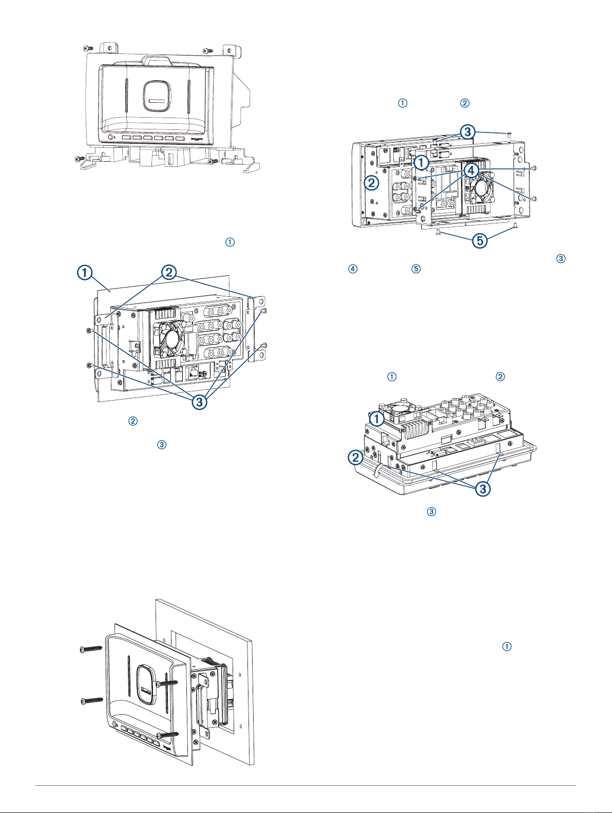
Installing the Bracket on the Dock for Ford® Vehicles
You should use the included screws to attach the bracket to the
dock.
1Remove the protective film from the gasket , and slide it
over the dock, with the adhesive facing the front of the dock.
2Place each bracket on the dock, aligning the holes on the
bracket with the holes on the side the dock.
3Using the included screws , secure each bracket to the
sides of the dock.
Installing the Dock in a Ford Dashboard
Before you can install the dock in the dashboard, you must
install the gasket and bracket on the dock.
The product package does not include the hardware required to
fasten the dock bracket to the dashboard.
1If necessary, remove the dashboard panel or components to
reach the stereo mounting location.
2From inside the dashboard, connect all necessary cables and
wires to the dock.
3Place the dock in the dashboard, and secure it using screws
through the top and bottom holes of the bracket.
4If necessary, reinstall all remaining dashboard components.
Installing the Bracket for Alante™ and Precept™
Vehicles
You should use the included screws to attach the bracket to the
dock.
1Place the bracket on the dock , aligning the holes on the
bracket with the holes on the sides and top of the dock.
2Using the included screws, secure the bracket to the top ,
sides , and bottom of the dock.
Installing the Dock in an Alante or Precept Dashboard
Before you can install the dock in the dashboard, you must
install the bracket on the dock.
You cannot use screws to secure the dock to the dashboard
panel. Folded tabs on the bracket hold the dock in place using
tension.
1If necessary, remove the dashboard panel or components to
reach the stereo mounting location.
2Place the dock in the dashboard panel .
3Fold down all of the tabs on the bracket to secure the dock
to the back of the dashboard panel.
4From inside the dashboard, connect all necessary cables and
wires to the dock.
5Place the dashboard panel in the dashboard and secure it to
the dashboard.
6If necessary, reinstall all remaining dashboard components.
Installing the Bracket on the Dock for Freightliner®
Vehicles
You should use the included screws to attach the bracket to the
dock.
1Remove the protective film from the gasket , and slide it
over the dock, with the adhesive facing the front of the dock.
3

2Place each bracket on the dock, aligning the holes on the
bracket with the holes on the side the dock.
3Using the included screws , secure each bracket to the
sides of the dock.
Installing the Dock in a Freightliner Dashboard
Before you can install the dock in the dashboard, you must
install the gasket and brackets on the dock.
The product package does not include the hardware required to
fasten the dock bracket to the dashboard.
1If necessary, remove the dashboard panel or components to
reach the stereo mounting location.
2From inside the dashboard, connect all necessary cables and
wires to the dock.
3Place the dock in the dashboard and secure it using screws
through the top and bottom holes of the bracket.
4If necessary, reinstall all remaining dashboard components.
Specifications
RV-BBT600 Series Remote Specifications
Operating
temperature range
From -20° to 60°C (from -4° to 140°F)
Charging
temperature range
(vehicle power)
From 0° to 40°C (from 32° to 104°F)
Power input type Vehicle power using RV-BBT600 series dock or
an approved mount accessory and vehicle
power cable. AC power using an optional
accessory for home or office use only.
Battery type Rechargeable lithium-ion, 3.7 Vdc
Input Maximum DC 5 V, 2 A
Wireless protocols 2.4 GHz Bluetooth® wireless technology
2.4 GHz Wi‑Fi® technology
© 2017 Garmin Ltd. or its subsidiaries
Garmin®, the Garmin logo, FUSION®, and the Fusion logo are trademarks of Garmin Ltd.
or its subsidiaries, registered in the USA and other countries. These trademarks may not
be used without the express permission of Garmin.
Sirius, XM and all related marks and logos are trademarks of Sirius XM Radio Inc.
Alante™ is a trademark of Jayco, Inc. Ford® is a registered trademark of Ford Motor
Company. Freightliner® is a registered trademark of Daimler Auto Group. Precept™ is a
trademark of Jayco, Inc. Sprinter™ is a trademark of Daimler Auto Group.
© 2017 Garmin Ltd. or its subsidiaries support.garmin.com
Other manuals for RV-BBT600 Series
1
Other Garmin Automobile Accessories manuals


