manuals.online logo
Brands
  1. Home
  2. •
  3. Brands
  4. •
  5. Garmin
  6. •
  7. Car Navigation System
  8. •
  9. Garmin NTX54-Nissan User manual

Garmin NTX54-Nissan User manual

NTX54-Nissan
Nissan/Infiniti Garmin Navigation System
NTV-KIT405
DS, BM
July 8, 2013
NTV-DOC138
3950 NW 120th Ave, Coral Springs, FL 33065 TEL 561-955-9770 FAX 561-955-9760
2 | P a g e
Agreement: End user agrees to use this product in compliance with all State and Federal laws. NAV-TV Corp. would not be held liable for misuse of its product.
If you do not agree, please discontinue use immediately and return product to place of purchase. This product is intended for off-road use and passenger
entertainment only.
Included Parts:
Needed Tools:
Long Phillips Screwdriver
NTX54-Nissan module
NTV-ASY184
Straight pick
Zip Ties
Velcro
Telescoping Magnet
Plastic panel tool
Garmin Navigation
system and GPS antenna
NTV-NAV009
NTX54 Power T-Harness
NTV-HAR232
OEM Nissan touch
screen monitor
NTV-NAV010
NTX54 Screen T-Harness
NTV-HAR233
Garmin Harness
NTV-HAR225
LCD Trim kit (optional)
NTV-431
USB Cable
NTV-CAB009
3 | P a g e
Agreement: End user agrees to use this product in compliance with all State and Federal laws. NAV-TV Corp. would not be held liable for misuse of its product.
If you do not agree, please discontinue use immediately and return product to place of purchase. This product is intended for off-road use and passenger
entertainment only.
The connector pin outs above are for the black mini Molex connectors that plug into the NTX-NIS/INF
interface module. The view is from the back side of the Molex connectors (the view you would see if
the connectors were plugged into the NTX-NIS/INF module). From left to right is the 18 pin mini Molex
from the 20 pin power plug T-harness, the 22 pin mini Molex from the 24 pin video T-harness and the
24 pin mini Molex from the 24 pin to 24 pin NTX-NIS/INF module to the NTX-54 navigation module.
Module connector layout
NTX54-Nissan Module pin out (wire side)
Video T-Harness (22-pin)
Power T-Harness (18-pin)
Navigation Harness (24-pin)
*Note: Wire colors may change without warning. Always reference pin locations, not
wire colors!
Video
input
Navigation
Harness
Video T-Harness
Power T-Harness
Power T-Harness (18-pin)
USB
(upda
tes)
Speaker OUT +
In From Radio +
Speaker OUT -
In From Radio -
4 | P a g e
Agreement: End user agrees to use this product in compliance with all State and Federal laws. NAV-TV Corp. would not be held liable for misuse of its product.
If you do not agree, please discontinue use immediately and return product to place of purchase. This product is intended for off-road use and passenger
entertainment only.
Overview:
The NTX Nissan/Infiniti is a touch screen Navigation interface for compatible 2008 to current Nissan and Infinity
vehicles. The module will also allow the integration of a video source or a front facing camera. During the installation
the original color LCD monitor will be replaced. The installation is performed entirely AT THE RADIO and not at the monitor.
FAILURE TO FOLLOW THESE INSTRUCTIONS MAY LEAD TO PRODUCT FAILURE OR AN AIRBAG MALFUNCTION LIGHT.
G37 Radio & Screen Removal:
Insert the pick tool or a small screwdriver
into the shift lock hole and depress the shift
lock mechanism
Make sure that the emergency brake is
engaged and then move the shifter into
reverse.
3
3
2
4
The accessory of the vehicle must be off during the next several steps. Make sure that
either the key is removed from the key cylinder or that the push to start switch is in the off
position. If this step is ignored you will receive an airbag light warning!
Remove the plastic trim ring around the shifter
using a plastic pry tool.
With a pick tool, remove the shift lock hole
cover.
1
5 | P a g e
Agreement: End user agrees to use this product in compliance with all State and Federal laws. NAV-TV Corp. would not be held liable for misuse of its product.
If you do not agree, please discontinue use immediately and return product to place of purchase. This product is intended for off-road use and passenger
entertainment only.
5
Remove the screws from the left and right
bottom corners and pull the HVAC panel
from the bottom up and away from the
dash.
Gently pull the top section back and away from the dash to
release the top clips. Make sure that the vehicle is off and
disconnect all the harnesses from the back of the HVAC panel.
DO NOT turn the key or push the push to start button until
after the HVAC panel has been plugged back in during later
steps.
Remove the screws on the bottom left and
right that holds the monitor trim in place.
These screws were hidden by the HVAC
panel.
Pull the monitor shroud up and back towards the rear of
the vehicle and remove it. The ribbon cable attached to
the shroud should have already been removed in step 6.
7
Remove the two screws holding the top of
the radio bracket and the bottom of the
monitor brackets.
Using a long Phillips screwdriver, remove the two screws holding
the bottom of the radio bracket. You may need the magnet to
retrieve these screws if they drop inside the dash.
9
6
8
10
6 | P a g e
Agreement: End user agrees to use this product in compliance with all State and Federal laws. NAV-TV Corp. would not be held liable for misuse of its product.
If you do not agree, please discontinue use immediately and return product to place of purchase. This product is intended for off-road use and passenger
entertainment only.
Using a soft pry tool remove the cover below
the HVAC panel by prying gently around it to
dislodge it from the retaining clips. Disconnect
all plugs and set it aside.
Remove the two screws at the bottom left and
right with a phillips screwdriver. Above and at a
45 degree angle behind these two screws are 2
more screws. You must use a long phillips
screwdriver to access them. Remove these
screws as well.
Armada Radio & Screen Removal: Warning! The ignition MUST be off!
Pull the radio out of the dash, disconnect all
wiring and set it aside.
Swing the bottom of the monitor upwards to release the
top of the monitor brackets from their U shaped top
mount. Note: There are no top bolts and only a locking
mount. Disconnect the monitor and set it aside.
11
12
Pull the radio out of the dash, disconnect all
wiring and set aside.
7 | P a g e
Agreement: End user agrees to use this product in compliance with all State and Federal laws. NAV-TV Corp. would not be held liable for misuse of its product.
If you do not agree, please discontinue use immediately and return product to place of purchase. This product is intended for off-road use and passenger
entertainment only.
All other Nissan & Infiniti vehicle Radio & Screen Removal: Warning! The ignition MUST be off
Screen Replacement ALL VEHICLES EXCEPT FX.
Using a soft pry tool, pry around the outside of
the HVAC fascia to release the clips all the way
around. Pull the entire fascia towards the back
of the vehicle to release the clips, disconnect all
the wiring harnesses and set aside.
Using a soft pry tool, pry around the outside of
the HVAC fascia to release the clips all the way
around. Pull the entire fascia towards the back
of the vehicle to release the clips, disconnect
all the wiring harnesses and set aside.
Remove the screws around the monitor
bracket, unplug the monitor and set the
monitor and bracket aside.
The removal of all other Nissan and Infiniti vehicle radios are similar to either the G37 or Armada. Remove the radio
and screen from the vehicle and then proceed to the next steps. MAKE SURE that the ignition is off in all
Nissan/Infiniti vehicles as the airbag indicator light is on the part of the dash that you will be removing. Although
it will cause no damage to the vehicle, the air bag indicator malfunction light will illuminate if the ignition is turn
on while this indictor light is unplugged.
Mount the included touch screen monitor into the bracket, making
sure that the angle side is facing the mark, secure it with the factory
screws and reinstall the monitor back into the vehicle.
Mark the bracket on the side where the
monitor has an angle. Remove and retain the
2 screws on each side of the factory monitor
and remove it from the bracket.
Beveled
corner of
touchscreen
is the
bottom
8 | P a g e
Agreement: End user agrees to use this product in compliance with all State and Federal laws. NAV-TV Corp. would not be held liable for misuse of its product.
If you do not agree, please discontinue use immediately and return product to place of purchase. This product is intended for off-road use and passenger
entertainment only.
Screen Replacement FX.
1. Follow the directions on the previous page under "Screen Replacement All Vehicles except FX" to remove the
factory monitor from the mounting bracket.
2. The original monitor in the FX has an oversized monitor housing. In order to replace the original monitor with the
new touch screen monitor you must use the included (FX Kit only) trim, shims and longer replacement screws to
center the new monitor in the mounting brackets.
3. Reinstall the new monitor and mounting bracket back into the vehicle and place the included (FX Kit only) trim
fascia around the new monitor. Note: The fascia is a pressure fit and does not require adhesive to stay in place.
Plug-and-play installation is performed at the radio for ALL VEHICLES.
At this stage the monitor should be reinstalled in the vehicle with the factory connector plugged into the monitor. If you have failed
to follow these instructions and ANY aftermarket harness is plugged in at the screen, disconnect it and insert the factory plug. In
vehicles where the screen mounts behind the fascia, like the Armada, the screen can be reattached with the factory screws and
mounted permanently. In vehicles like the G37 where the radio top mounts are in the same location as the monitor bottom screws,
reattach the top mechanical hinge mount but leave the bottom retaining screws out until the installation is completed and only
reattach during final reassembly.
BACK OF ALL RADIOS
20 Pin Power
Connector
Location of the factory reverse signal
(12 volt + while in reverse) TEST!
24 Pin Screen Connector
9 | P a g e
Agreement: End user agrees to use this product in compliance with all State and Federal laws. NAV-TV Corp. would not be held liable for misuse of its product.
If you do not agree, please discontinue use immediately and return product to place of purchase. This product is intended for off-road use and passenger
entertainment only.
Installation of the T-harnesses for all vehicles
1. Plug the female end of the 24 pin Video T-Harness into the factory male 24 pin plug behind the radio.
2. Plug the female end of the 20 pin Power T-harness into the factory male 20 pin plug behind the radio.
3. Run both the extension harnesses with the 22 pin and 18 pin black mini Molex ends to a location near the radio
with enough room to properly house and mount the NTX-NIS/INF integration module.
4. If installing a video source, or a front or camera, continue with instruction 5. If no camera or video source is being
installed skip to instruction 8.
Labeled ‘To
Radio Only’
10 | P a g e
Agreement: End user agrees to use this product in compliance with all State and Federal laws. NAV-TV Corp. would not be held liable for misuse of its product.
If you do not agree, please discontinue use immediately and return product to place of purchase. This product is intended for off-road use and passenger
entertainment only.
5. If installing a video source or front camera, connect the RCA from the device to the NTX-NIS/INF interface at the
"video in" RCA connection. As long as your device does not draw in excess of 1 AMP you may connect the power
and ground of the device to the wires on the 20 to 20 pin T-harness labeled "ground" and "12v+ CAM out". If in
doubt measure the current demand or use a relay.
6. If installing an aftermarket reverse camera, connect the RCA from the rear view camera to the NTX-NIS/INF
interface at the "video in" RCA connection. When installing the rear view camera, run an additional wire with the
power, ground and RCA from the camera that you will tie in to the reverse wire at the rear of the vehicle (if not
found in the 32 pin connector –see graphic on page 11). This wire will connect to the PINK “INPUT”wire on the 20
pin to 20 pin T-harness. Whenever the PINK "INPUT" wire sees 12v (+), the video input will be seen automatically
on the monitor. Attach the power and ground of the rear view camera to the Ground & "12v+ CAM out" at the 20
pin to 20 pin Power T-harness. If the rear view camera requires more than 1 amp of current make sure to use a
relay.
7. AREAS WITH TUNNELS, PARKING GARAGES AND TALL BUILDINGS (OPTIONAL). The NTX54 navigation system
operates via a technology called "dead reckoning", utilizing only GPS satellite information to detect speed and
location. In some areas with a large amount of obstacles that may block the GPS antennas ability to receive GPS
coordinates, such as tunnels, parking garages and tall buildings, the NTX54's performance may be affected. If you
experience issues in these areas we recommend connecting the vehicle VSS (speed sense wire) and the vehicle
reverse signal to the "VSS in" and "VRS in" at the 20 pin to 20 pin T-harness.
8. Plug the 22 pin extension harness (black molex plug) into the NTX54-Nissan interface port labeled ‘Screen’.
9. Plug the 18 pin extension harness (black molex plug) into the NTX54-Nissan interface port labeled ‘Radio’.
10. Plug the black 24 pin molex of the Navigation harness into the NTX54-Nissan interface port labeled ‘Navigation’.
11. If the vehicle DOES NOT have Bose, the turn-by-turn directions and all audio commands will be heard automatically
through the driver's front speaker. You may skip to step 13 for all NON BOSE sound systems.
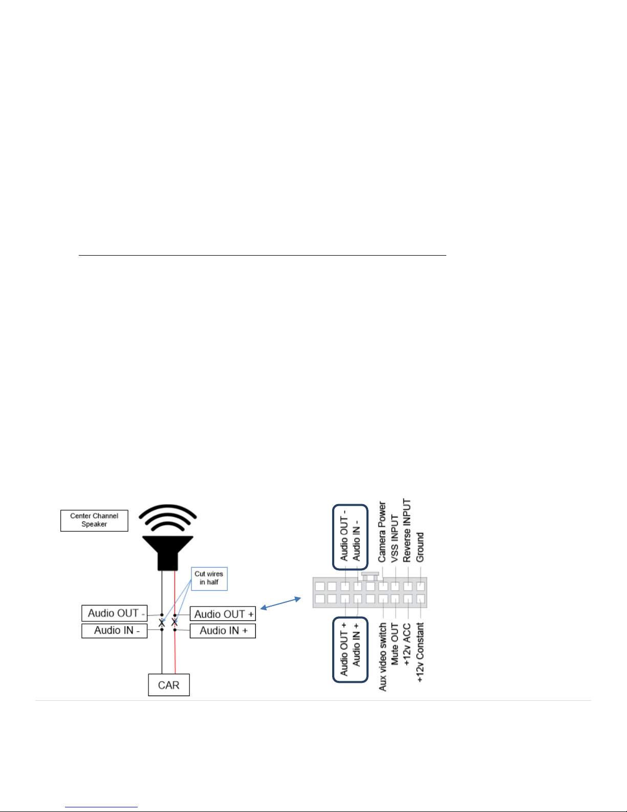
12. If the vehicle has a Bose sound system you must use the audio IN and audio OUT wires (in the POWER harness) to
break open the center channel speaker. Refer to the diagram below.
- Power harness
- This connector view is from the
wire side
- Cut NTX54 wires near the T-
section
- Cut the factory speaker signal
leads in half
- The Audio IN/OUT wire pairs
will be labeled:
Audio Out: ‘Speaker OUT’
Audio In: ‘In From Radio’
11 | P a g e
Agreement: End user agrees to use this product in compliance with all State and Federal laws. NAV-TV Corp. would not be held liable for misuse of its product.
If you do not agree, please discontinue use immediately and return product to place of purchase. This product is intended for off-road use and passenger
entertainment only.
If adding an aftermarket backup camera:
1. Connect the camera’s composite video cable to the
NTX54 ‘Aux Video’ port (silver box).
2. Program the NTX module for both video input and
rear view camera (page 12).
3. Tap the car’s reverse wire and connect it to the PINK
‘INPUT’ wire from NTX power harness. The factory
reverse wire can be found in most Nissan/Infiniti’s in
the 32 pin connector behind the radio.
If only adding a video source (such as DVD video, front cam etc.):
Supply the video signal to the NTX54 module’s ‘Aux Video’ port. To display the video on screen,
press the top left corner of the touch screen while in radio mode for 2 seconds (page 13).
NTX-54 Garmin Navigation
13. Locate a spot near the mounting location of the NTX-NIS/INF integration module with enough room to house and
mount the NTX54 navigation brain. Run the Navigation harness from the NTX-NIS/INF integration module to the
NTX54 navigation module and plug it in.
14. The included GPS antenna needs to be installed right side up in a location with a clear line of sight to the sky. The
antenna can be mounted on top of the dash or below the plastic dash pad as long as there is no metal obstruction.
To avoid the antenna from moving we recommend mounting it with either Velcro or double sided tape.
15. Run the GPS antenna cable to the NTX54 navigation box and plug it into the GPS antenna connector jack. Excess
cable should be looped neatly into a circle to eliminate
kinking of the cable and zip tied securely inside the dash or
kick panel.
16. Secure the NTX54 navigation and NTX-NIS/INF integration
module in their mounting spots with Velcro. For added
stability a large zip tie may also be used.
17. Secure all cabling to existing wiring harnesses or bracket
with zip ties making sure that they are not routed near
moving parts or sharp metal surfaces.
18. Reinstall the radio and dash bezel in the reverse order of
removal and test the Navigation and camera functions.
Make sure that the ignition is not turned on until after the HVAC panel is fully plugged in. Proceed to the "setup"
section below.
GPS Antenna Connector Power Connector
12 | P a g e
Agreement: End user agrees to use this product in compliance with all State and Federal laws. NAV-TV Corp. would not be held liable for misuse of its product. If you do
not agree, please discontinue use immediately and return product to place of purchase. This product is intended for off-road use and passenger entertainment only.
NTX-54 Nissan/Infiniti Navigation System
wire:
Programming PINK ‘INPUT’ wire:
Setup:
IF YOU ARE NOT INSTALLING ANY AFTERMARKET CAMERAS OR VIDEO INPUT, SKIP THIS SECTION AND GO STRAIGHT TO THE
"OPERATION" SECTION.
Note:
-These programming sequences only need to be performed one time. To deprogram, just repeat the above step(s).
- If the factory image does not reappear, press anywhere on the touchscreen. When the screen returns the factory
image, the feature should be programmed.
When this wire is programmed, the screen will
display ‘Aux Video’ from the silver NTX54 module
when the PINK ‘INPUT’ wire sees 12v (+), regardless
of what source is currently displayed. This must be
programmed if adding a rear camera.
While in the factory screen mode, press and hold the
top right corner of the screen until the screen goes
completely black (this will take about 20 seconds).
Release the top right corner and wait until the
factory image can be seen again.
Quick Start User’s Guide
Programming PINK ‘INPUT’ wire for REV Cam:
13 | P a g e
Agreement: End user agrees to use this product in compliance with all State and Federal laws. NAV-TV Corp. would not be held liable for misuse of its product. If you do
not agree, please discontinue use immediately and return product to place of purchase. This product is intended for off-road use and passenger entertainment only.
Operation:
Note:
For Video input: This will only display the AFTERMARKET camera/video source from the NTX54 module and will not
force the factory rear view camera on if equipped.
14 | P a g e
Agreement: End user agrees to use this product in compliance with all State and Federal laws. NAV-TV Corp. would not be held liable for misuse of its product. If you do
not agree, please discontinue use immediately and return product to place of purchase. This product is intended for off-road use and passenger entertainment only.
FAQ’s
Q. I’ve connected everything, but I have no image on the screen.
A. Press and hold the bottom left corner of the touch screen for 2 seconds (so as to bring it back to the factory screen
from NAV mode) to rule out navigation mode causing the issue.
Q. I hear no audio when NAV guidance playback should be heard.
A. Verify that the external speaker is plugged into the Garmin harness (if BOSE equipped). If not BOSE equipped, make
sure the 3.5mm audio cable (part of the GARMIN harness) is connected to the 3.5mm audio input of the same harness.
Q. I’ve installed the NTX54 system, and now my factory reverse camera does not function.
A. You must connect the vehicle reverse wire to the purple wire on the NTX54 power harness labeled ‘reverse’.
Q. While attempting to program the NTX54, the screen jumps to Garmin NAV mode.
A. You’re either letting up too soon or moving your finger (assuming you’re holding the correct corner). Commit to the
spot and after you’ve made contact with your finger press firmly for 25 seconds and do not let up. The screen should go
black or post the image when programmed. Also, programming can only take place in the factory screen and NOT in
NAV mode.
For technical assistance on installation or usage call NAV-TV at (866) 477-3336.

Other Garmin Car Navigation System manuals

Garmin nüvi 2240 Instruction manual

Garmin

Garmin nüvi 2240 Instruction manual

Garmin nuvi 2515 Instruction manual

Garmin

Garmin nuvi 2515 Instruction manual

Garmin nuvi 800 series Instruction manual

Garmin

Garmin nuvi 800 series Instruction manual

Garmin DEZL OTR700 User manual

Garmin

Garmin DEZL OTR700 User manual

Garmin 2610/2650 User manual

Garmin

Garmin 2610/2650 User manual

Garmin Streetpilot C320 User manual

Garmin

Garmin Streetpilot C320 User manual

Garmin StreetPilot 7200 User manual

Garmin

Garmin StreetPilot 7200 User manual

Garmin zumo 395LM User manual

Garmin

Garmin zumo 395LM User manual

Garmin SEAT Portable System User manual

Garmin

Garmin SEAT Portable System User manual

Garmin GPS 19x NMEA 0183 User manual

Garmin

Garmin GPS 19x NMEA 0183 User manual

Garmin StreetPilot 2620 User manual

Garmin

Garmin StreetPilot 2620 User manual

Garmin nuvi 800 series Instruction manual

Garmin

Garmin nuvi 800 series Instruction manual

Garmin nuvi 360 User manual

Garmin

Garmin nuvi 360 User manual

Garmin nuvi 140T Series Instruction manual

Garmin

Garmin nuvi 140T Series Instruction manual

Garmin G5000 Technical specifications

Garmin

Garmin G5000 Technical specifications

Garmin VIEO RV 850 Series User manual

Garmin

Garmin VIEO RV 850 Series User manual

Garmin HUD User manual

Garmin

Garmin HUD User manual

Garmin StreetPilot 7500 User manual

Garmin

Garmin StreetPilot 7500 User manual

Garmin StreetPilot c340 User manual

Garmin

Garmin StreetPilot c340 User manual

Garmin StreetPilot c330 User manual

Garmin

Garmin StreetPilot c330 User manual

Garmin AERA 660 Manual

Garmin

Garmin AERA 660 Manual

Garmin nuvi 705 series User manual

Garmin

Garmin nuvi 705 series User manual

Garmin 880 Instruction manual

Garmin

Garmin 880 Instruction manual

Garmin nuvi 660 User manual

Garmin

Garmin nuvi 660 User manual

Popular Car Navigation System manuals by other brands

Navigon MN7 Windows Mobile (PDA) user manual

Navigon

Navigon MN7 Windows Mobile (PDA) user manual

Xomax XM-2DA6901 instruction manual

Xomax

Xomax XM-2DA6901 instruction manual

Nav TV RGB PCM3.1 Kit manual

Nav TV

Nav TV RGB PCM3.1 Kit manual

Chevrolet ACADIA - 2011 Navigation manual

Chevrolet

Chevrolet ACADIA - 2011 Navigation manual

Nav TV NTV-KIT597 user manual

Nav TV

Nav TV NTV-KIT597 user manual

Snooper AVN S7000 user manual

Snooper

Snooper AVN S7000 user manual

Toyota RAV4 2011 owner's manual

Toyota

Toyota RAV4 2011 owner's manual

Alpine INE-W960HDMI owner's manual

Alpine

Alpine INE-W960HDMI owner's manual

Magellan RoadMate 300 Reference manual

Magellan

Magellan RoadMate 300 Reference manual

Toyota Verso TNS510 user manual

Toyota

Toyota Verso TNS510 user manual

Motorola TN20 - MOTONAV - Automotive GPS Receiver quick start guide

Motorola

Motorola TN20 - MOTONAV - Automotive GPS Receiver quick start guide

Goodyear GY500X user guide

Goodyear

Goodyear GY500X user guide

Navitel E707 MAGNETIC user manual

Navitel

Navitel E707 MAGNETIC user manual

Clarion QY-8200 Series manual

Clarion

Clarion QY-8200 Series manual

Toyota TNS 300 installation instructions

Toyota

Toyota TNS 300 installation instructions

tradetec TR2260 user manual

tradetec

tradetec TR2260 user manual

Navos 407632 manual

Navos

Navos 407632 manual

Peterbilt PACCAR Operator's manual

Peterbilt

Peterbilt PACCAR Operator's manual

manuals.online logo
manuals.online logoBrands
  • About & Mission
  • Contact us
  • Privacy Policy
  • Terms and Conditions

Copyright 2025 Manuals.Online. All Rights Reserved.