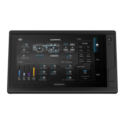
Garmin SERV User manual

GARMIN SERV™
INSTALLATION INSTRUCTIONS
Important Safety Information
WARNING
See the Important Safety and Product Information guide in the product box for product warnings and other
important information.
Garmin® strongly recommends having an experienced installer with the proper knowledge of electrical systems
install the device. Incorrectly wiring the power cable can result in damage to the vehicle or the battery and can
cause bodily injury.
To prevent the possibility of injury or product damage caused by fire or overheating, you must install an
appropriate fuse as indicated in the product specifications. Connecting the power cable without the appropriate
fuse in place voids the product warranty.
CAUTION
To avoid possible personal injury, always wear safety goggles, ear protection, and a dust mask when drilling,
cutting, or sanding.
NOTICE
To obtain the best performance and to avoid damage to the vehicle, install the device according to these
instructions.
Read all installation instructions before proceeding with the installation. If you experience difficulty during the
installation, contact Garmin Support.
When drilling or cutting, always check what is on the opposite side of the surface to avoid damaging the vehicle.
Connecting to a Wireless Network
1Select Settings > Network & internet > Wi-Fi.
2If necessary, select the toggle switch to turn on wireless network technology.
3Select a wireless network.
4If necessary, enter the encryption key.
The device connects to the wireless network. The device remembers the network information and connects
automatically when you return to this location in the future.
GUID-7994A3E6-F538-4082-960B-86854B3351AA v1July 2023

Updating Software Using a Wi‑Fi®Network
NOTICE
Software updates may require the device to download large files. Regular data limits or charges from your
internet service provider apply. Contact your internet service provider for more information about data limits or
charges.
You can update the software by connecting your device to a Wi‑Fi network that provides access to the internet.
1Connect the device to a Wi‑Fi network (Connecting to a Wireless Network, page1).
While connected to a Wi‑Fi network, the device checks for available updates automatically and displays a
notification when an update is available.
2Select > Software Updates.
The device displays available software updates. When an update is available, Update Available appears.
3Select Download.
4Follow the on-screen instructions on your device to complete the update process.
5Keep the device connected to external power and within range of the Wi‑Fi network until the update process
is complete.
Contacting Garmin Support
• Go to support.garmin.com for help and information, such as product manuals, frequently asked questions,
videos, and customer support.
• In the USA, call 913-397-8200 or 1-800-800-1020.
• In the UK, call 0808 238 0000.
• In Europe, call +44 (0) 870 850 1241.
Tools Needed
• Drill and drill bits
◦Preparing the surface for cutting:
9mm (3/8in.) bit
◦Installs using wood screws:
2.8mm (7/64in.) bit
◦Installs using the nut plate:
3.5mm (9/64in.) bit
4mm (5/32in.) bit
• #2 Phillips screwdriver
• Jigsaw or rotary tool
• File and sandpaper
2

Mounting Considerations
NOTICE
This device should be mounted in a location that is not exposed to extreme temperatures or conditions. The
temperature range for this device is listed in the product specifications. Extended exposure to temperatures
exceeding the specified temperature range, in storage or operating conditions, may cause device failure.
Extreme-temperature-induced damage and related consequences are not covered by the warranty.
When selecting a mounting location, you should observe these considerations.
• The location should allow for easy access to all device interfaces, if applicable.
• The location must be strong enough to support the weight of the device and protect it from excessive
vibration or shock.
• The location must allow room for the routing and connection of all cables.
• The location must not be a flat, horizontal surface. The location should be in a vertical angle.
You should test the location and viewing angle before you install the device. High viewing angles from above
and below the display may result in a poor image.
• The device must be oriented with the top of the device pointing to the top of the mounting surface.
• You must use the included cable ties to keep the cables in place and to take the weight off the connectors.
Do not overtighten the cable ties.
Mounting the Device
NOTICE
Be careful when cutting the hole to flush mount the device. There is only a small amount of clearance between
the case and the mounting holes, and cutting the hole too large could compromise the stability of the device
after it is mounted.
To avoid potential damage to the device, use only the included screws to mount it. Using screws other than the
ones included will void your warranty.
The included template and hardware can be used to flush mount the device in your dashboard. There are two
options for hardware based on the mounting surface material.
• You can drill pilot holes and use the included wood screws.
• You can drill holes and use the included nut plates and machine screws. The nut plates can add stability to a
thinner surface.
1Trim the template and make sure it fits in the location where you want to mount the device.
2Secure the template to the selected location.
3Using a 9mm (3/8in.) drill bit, drill one or more of the holes inside the corners of the solid line on the
template to prepare the mounting surface for cutting.
4Using a jigsaw or rotary tool, cut the mounting surface along the inside of the solid line indicated on the
template.
5Place the device in the cutout to test the fit.
6If necessary, use a file and sandpaper to refine the size of the cutout.
7After the device fits correctly in the cutout, ensure the mounting holes on the device line up with the holes on
the template.
8If the mounting holes on the device do not line up, mark the new hole locations.
9Based on your mounting method, drill the outer holes on the template:
• Drill 2.8mm (7/64in.) pilot holes for the included wood screws, and skip to step 18.
• Drill 4mm (5/32in.) holes for the included nut plate and flat-head screws.
3

10 If using the nut plates, starting in one corner of the template, place a
nut plate over the hole drilled in the previous step.
The other hole on the nut plate should line up with the inner hole on
the template.
11 If the other hole on the nut plate does not line up with the inner hole on
the template, mark the new location.
12 Repeat for each nut plate.
13 Using a 3.5mm (9/64in.) drill bit, drill the inner holes.
14 Remove the template from the mounting surface.
15 Starting in one corner of the mounting location, place a nut plate on the back of the mounting surface,
lining up the inner and outer holes.
The raised portion (the collar) of the nut plate should fit into the outer hole.
16 Secure the nut plate to the mounting surface by fastening an included M3 pan-head screw through the
inner 3.5mm (9/64in.) hole.
17 Repeat for each nut plate.
18 If you will not have access to the back of the device after you mount it, connect all necessary cables to the
device and install a memory card before placing the device into the cutout.
19 Place the device into the cutout.
20 Secure the device to the mounting surface using the included M3 flat-head screws or wood screws ,
depending on the mounting method.
21 Snap the bezel into place.
4

Connector Identification
Item Label Notes
POWER Requires 5A fuse (not included)
CAN Connects to vehicle control systems using an adapter (not included)
NETWORK Connects to a network
Power Connection
When connecting the device to power, you must connect the red, orange, and black wires to the power source.
The orange and red wires have different functions, and the method you use to connect them to power depends
on how you plan to use the device in your vehicle.
Red wire
• WARNING
If a 5A circuit breaker is not available in the vehicle, you must connect this wire to power through a 5A fuse (not
included).
This wire provides power to the device.
•NOTICE
If power is lost from this wire, the system clock will turn off.
• You must connect this wire to power through a 5A circuit breaker or fuse.
• If it is necessary to extend this wire, use 18AWG (.75mm2) wire. For extensions longer than 1m (3ft.),
use 12AWG (3.31mm²) wire.
5

Orange wire
• WARNING
You must connect this wire to power through a 5A fuse (not included).
• You can connect this wire to the same power source as the red wire through the ignition or to a manual
switch. This enables you to turn the device on and off automatically when you turn the vehicle on and off,
or when you activate the switch.
• If it is necessary to extend this wire, use 18AWG (0.75mm2) wire.
Black wire
• This is the ground wire, and you must connect it to the negative terminal of the power source or to a
common ground.
• If it is necessary to extend this wire, use 18AWG (.75mm2) wire. For extensions longer than 1m (3ft.),
use 12AWG (3.31mm2) wire.
Opening the Installer Settings
1Select All Apps > Settings > Vehicle Integration.
2Tap IP Address ten times.
Several options are enabled that are intended for installers only. The options are available until you turn the
device off and on.
Saving Configuration Files
You can save configuration files for digital switching pages and more to a memory card and load them to other
compatible devices. This is useful when you have multiple devices that use the same configuration.
1Insert a memory card.
2From the installer settings (Opening the Installer Settings, page6), select Settings > Vehicle Integration >
Configuration Sharing.
3Select Copy Export Archive to Removable Storage > Start.
The device saves an archived file to the memory card.
4Select Close.
5Remove the memory card from the device.
6Insert the memory card into a new device.
The configuration file imports.
Troubleshooting
My device will not turn on or keeps turning off
Devices erratically turning off or not turning on could indicate an issue with the power supplied to the device.
Complete these steps to attempt to troubleshoot the cause of the power issue.
• Make sure the power source is generating power.
You can check this in various ways. For example, you can check whether other devices powered by the
source are functioning.
• Examine the fuse.
You should make sure the proper size fuse is installed (refer to the product specifications for the exact fuse
size needed). You should also check the fuse to make sure there is still a connection inside of the fuse. You
can test the fuse using a multimeter. If the fuse is good, the multimeter reads 0ohm.
• Make sure the device is receiving at least 10Vdc.
To check the voltage, you should measure the female power and ground sockets of the power cable for DC
voltage. If the voltage is less than 10Vdc, the device will not turn on.
• If the device is receiving enough power but does not turn on, contact Garmin Support.
6

Specifications
All Models
Specification Measurement
Temperature range From -10° to 60°C (from 14° to 140°F)
Input voltage From 10 to 32Vdc
Fuse 5A
Memory card (not included) 1 microSD® card slot; 2 TB max. card size
Wireless frequency and transmit power 2.4 GHz @ 14.3 dBm maximum
Seven-inch Models
Specification Measurement
Dimensions (W × H × D) 209.2 × 123.3 × 38.6mm
8.24 × 4.85 × 1.52in.)
Display size (W × H) 153.2 × 90.1mm (6.03 × 3.55in.)
Weight 455g (1.00lb.)
Max. power usage 5W
Typical current draw at 12Vdc 0.25A
Max. current draw at 12Vdc 0.5A
Ten-inch Models
Specification Measurement
Dimensions (W × H × D) 281.2 × 176.4 × 38.7mm (11.07 × 6.94 × 1.52in.)
Display size (W × H) 217.6 × 136.4mm (8.57 × 5.37in.)
Weight 728g (1.6lb.)
Max. power usage 7.5W
Typical current draw at 12Vdc 0.5A
Max. current draw at 12Vdc 0.75A
© 2023 Garmin Ltd. or its subsidiaries
Garmin®, the Garmin logo, Garmin SERV™, and EmpirBus™ are trademarks of Garmin Ltd. or its subsidiaries, registered in the USA and other countries. These trademarks
may not be used without the express permission of Garmin.
7

© 2023 Garmin Ltd. or its subsidiaries support.garmin.com
Other manuals for SERV
1
Table of contents
Other Garmin Monitor manuals
Garmin
Garmin TD 50 User manual
Garmin
Garmin GMX 200 User manual

Garmin
Garmin GMX 200 User manual

Garmin
Garmin A03985 Instruction manual
Garmin
Garmin TD 50 User manual
Garmin
Garmin VIEO RV 852 Instruction manual
Garmin
Garmin GPSMAP 8400 series User manual
Garmin
Garmin GPSMAP 7X3 User manual
Garmin
Garmin VIEO RV 752 Instruction manual

Garmin
Garmin GPSMAP 16X3 User manual

