Garmin GMA 340 User manual

GMA
340
AUDIO PANEL
JUIAINTENANCE MANUAL
Garmin International
1200
E.
151"
Street
Olathe,
KS
66062
USA
1
90-00
1
49-02
(Rev
B)
June
2001
3
The document reference is online, please check the correspondence between the online documentation and the printed version.
0
Copyright
1998-2001
GAMIN
Corporation
All
Rights Reserved
REVISION
REVISION
DATE
A 1/4/99
B
61710
1
Except
as
expressly provided herein, no part ofthis manual may be reproduced, copied, transmitted, disseminated, downloaded or
stored in any storage medium, for any purpose without the express prior written consent of GARMIN Corporation. GARMIN
Corporation hereby grants permission to download a single copy of this manual and of any revision to this manual onto
a
hard
drive or other electronic storage medium to be viewed and to print one copy of this manual or of any revision hereto, provided that
such electronic or printed copy of this manual or revision must contain the complete text of this copyright notice and provided
hrtherthat any unauthorized commercial distribution ofthis manual or any revision hereto is strictly prohibited.
DESCRIPTION
ECO
#
-
Initial
Release
Add 340 Dual
ADF
and field
replacement
of
main
board.
15949
GARMIN
International,
Inc.
1200
E.
15lStStreet
Olathe,
KS
66062
USA
Telephone: 913-397-8200,Dealer
Line:
1-800-800-1420
Web SiteAddress:
www.mrmin.com
INFORMATION
SUBJECT
TO
EXPORT
CONTROL
LAWS
This document may contain information which is subject to the Export Administration Regulations ("EAR") issued by the United
States Department of Commerce
(1
5
CFR, Chapter VII, Subchapter C) and which may not be exported, released, or disclosedto
foreign nationals inside or outside of the United States without first obtaining an export license. A violation of the EAR may be
subject to
a
penalty of up to
10
years imprisonment and
a
fine ofup to
$1,000,000
under Section
2410
of the Export
Administration Act of
1979.
Include this notice with any reproduced portion ofthis document.
190-00
149-02Rev
B
The document reference is online, please check the correspondence between the online documentation and the printed version.

TABLE
OF
CONTENTS
SECTION
1
DESCFUPTIONAND OPERATION
PARAGRAPH PAGE
1.1 INTRODUCTION
.............................................................................................................................
1-1
1.2 GENERAL DESCRIPTION
..............................................................................................................
1-1
1.3 THEORY
OF
OPERATION
.............................................................................................................
1-2
SECTION
2
SPECIAL TESTEQUIPMENT
2.1 INTRODUCTION
.............................................................................................................................
2-1
2.2 GMA 340 REAR CONNECTORS
....................................................................................................
2-1
2.3 GMA 340 TEST PANEL
..................................................................................................................
2-1
2.4 TEST HARNESS.
J
1
AND 52 PIN ASSIGNMENTS
......................................................................
2-4
SECTION
3
TROUBLESHOOTING
3.1 TROUBLESHOOTING
....................................................................................................................
3-1
3.2 TROUBLESHOOTING PROCEDURES
..........................................................................................
3-1
3.3 POWER ON CHECK
........................................................................................................................
3-5
3.4 28
V
LIGHTING
...............................................................................................................................
3-5
3.5 14
V
LIGHTING
...............................................................................................................................
3-5
3.6 PTT ANNUCIATOR CHECK
..........................................................................................................
3-5
SECTION
4
DISASSEMBLY AND REASSEMBLY
4.1 INTRODUCTION
.............................................................................................................................
4-1
4.2 TOOLS REQUIRED
.........................................................................................................................
4-1
4.3 DISASSEMBLING THE UNIT
........................................................................................................
4-1
4.4 REASSEMBLY
.................................................................................................................................
4-3
190-00
149-02
Rev
B
I
The document reference is online, please check the correspondence between the online documentation and the printed version.

SECTION
5
TESTING
5.1 GENERAL
.........................................................................................................................................
5-1
5.2 ADJUSTMENT/MEASUREMENT ACCURACY
..........................................................................
5-1
5.3
5.4
5.5
5.6 TEST PANEL
....................................................................................................................................
5-2
5.7 BENCH TESTING
............................................................................................................................
5-2
5.8 TEST EQUIPMENT SETUP
............................................................................................................
5-2
5.9 STANDARD TEST SIGNALS
.........................................................................................................
5-5
5.10 POWER OFF CHECK
......................................................................................................................
5-6
5.1
1
POWER ON CHECK
........................................................................................................................
5-6
5.12 LOADED MICROPHONE VOLTAGE INPUTS
.............................................................................
5-7
5.13 PILOT PTT TESTS
...........................................................................................................................
5-7
5.14 FUNCTIONAL TEST
.......................................................................................................................
5-8
TEST EQUIPMENT PRECAUTIONS
.............................................................................................
5-1
REQUIRED TEST EQUIPMENT
....................................................................................................
5-2
REAR CONNECTORS PRECAUTION
...........................................................................................
5-1
SECTION
6
REPLACEABLEASSEMBLIES
6.1 LIST
OF
REPLACEABLE PARTS
..................................................................................................
6-1
SECTION
7
ASSEMBLY DRAWINGS
7.1 ASSEMBLY DRAWINGS
...............................................................................................................
7-1
11
190-001
49-02
Rev
B
The document reference is online, please check the correspondence between the online documentation and the printed version.

LIST OF FIGURES
FIGURE PAGE
2-1 GMA 340 Rear Connectors (Viewed from the Rear)
........................................................................
2-1
2-2 Typical Test Panel Layout
.................................................................................................................
2-3
2-3 Test Panel Schematic Diagram
..........................................................................................................
2-6
2-4 Coax Cable Assembly
.....................................................................................................................
2-10
3-1 Front Panel Connector Detail
............................................................................................................
3-2
3-2
3-3
5-1
GMA 340 Test Connections
..............................................................................................................
5-3
7-1 GMA 340 Front Panel Assembly
......................................................................................................
7-1
7-2 Marker Lamp Rack Assembly. Front and Rear Detail
......................................................................
7-1
7-3 GMA 340 Final Assembly
.................................................................................................................
7-2
Main Board Component Location. Partial Layout
............................................................................
3-3
Power Input Board
.............................................................................................................................
3-4
LIST
OF
TABLES
Table PAGE
2.1
.
Test Panel Parts List
..........................................................................................................................
2-2
2.2
.
J1
and 52 Pin Assignments
................................................................................................................
2-5
3.1. Front Panel Connector Detail
............................................................................................................
3-2
3-2 Main Board Connector Detail
...........................................................................................................
3-3
3.3. Power Input Board Connector Detail
................................................................................................
3-4
Field Replaceable Parts List
..............................................................................................................
6-1
6-1
...
190-00149-02
Rev
B
111
The document reference is online, please check the correspondence between the online documentation and the printed version.

This page intentionally left blank.
iv
190-001
49-02
Rev
B
The document reference is online, please check the correspondence between the online documentation and the printed version.

SECTION
1
DESCRIPTION AND OPERATION
1.1
INTRODUCTION
This manual provides functional testing and assembly-levelrepair information for the GARMIN GMA 340,
GMA 340H and GMA 340 Dual ADF Audio Panels. Reference to GMA 340 throughout this manual refers to all
versions of the unit. Information pertaining to the installation and operating instructions can be found in the
GMA 340 Audio Panel Installation Manual, 190-00149-0
1.
This manual is designed to aid the bench technician
in isolating failures
co
the assembly level only. If necessary, the GMA 340 can be returned to GARMIN for all
service work, including maintenance and repair. Contact GARMIN at the following address for more details:
GARMIN
1200
E.
151st
Street
Olathe,
KS
66062
1-913-397-8200 or 1-800-800-1020
1.2
GENERALDESCRIPTION
The GARMIN GMA 340
is
a
panel mounted TSO’d audio panel that provides control of the aircraft audio
system. The GMA 340 provides flexibility in switching up to three microphone and audio transceiver
communication inputs. Audio selection ofNAV 1,NAV 2, ADF, DME and marker audio is available on the
GMA 340 and GMA 340H. In addition, selection of ADF 1and ADF 2 is provided on the GMA 340 Dual ADF.
The GMA 340 includes a voice activated (VOX) intercom system and a three-lamp marker beacon receiver and
display. One or two stereo entertainment inputs are also provided. (One on the GMA 340 Dual ADF, two on the
other units.)
The VOX intercom uses rotary knobs for volume and squelch adjustment while selection of
all
other functions is
accomplished with the use of pushbuttons.
Marker HI and LO and button annunciation is accomplished with LED devices. Front panel backlightingof
button function, squelch and volume control knobs is provided by LED’Scontrolled by the aircraft lightingbus.
On the GMA 340 and GMA 340H the split com function allows the pilot and copilot to talk on Com
1
and Com
2
simultaneously.
The unit is constructed from high quality materials and uses surfacemount components extensively. Specialized
equipment and procedures are required to repair circuit boards having surface-mounted components. GARMIN
does not authorize the repair of GMA 340 circuit boards. If necessary, circuit boards and assemblies for the
GMA 340 can be economically replaced through the GARMIN board exchange program.
The following assemblies and printed circuit boards can be field replaced:
0
Front Panel Assembly-Contains the front panel bezel, button key cap assembly, marker beacon lamp
assembly and front panel board assembly.
0
Marker Beacon Lamp Rack Assembly-Contains marker beacon incandescent lamps and lamp rack.
Fits onto the front panel assembly.
0
Flexible Circuit Cables-Connects the frontpanel to the main circuit board assembly.
190-00149-02
Rev
B
1-1
The document reference is online, please check the correspondence between the online documentation and the printed version.
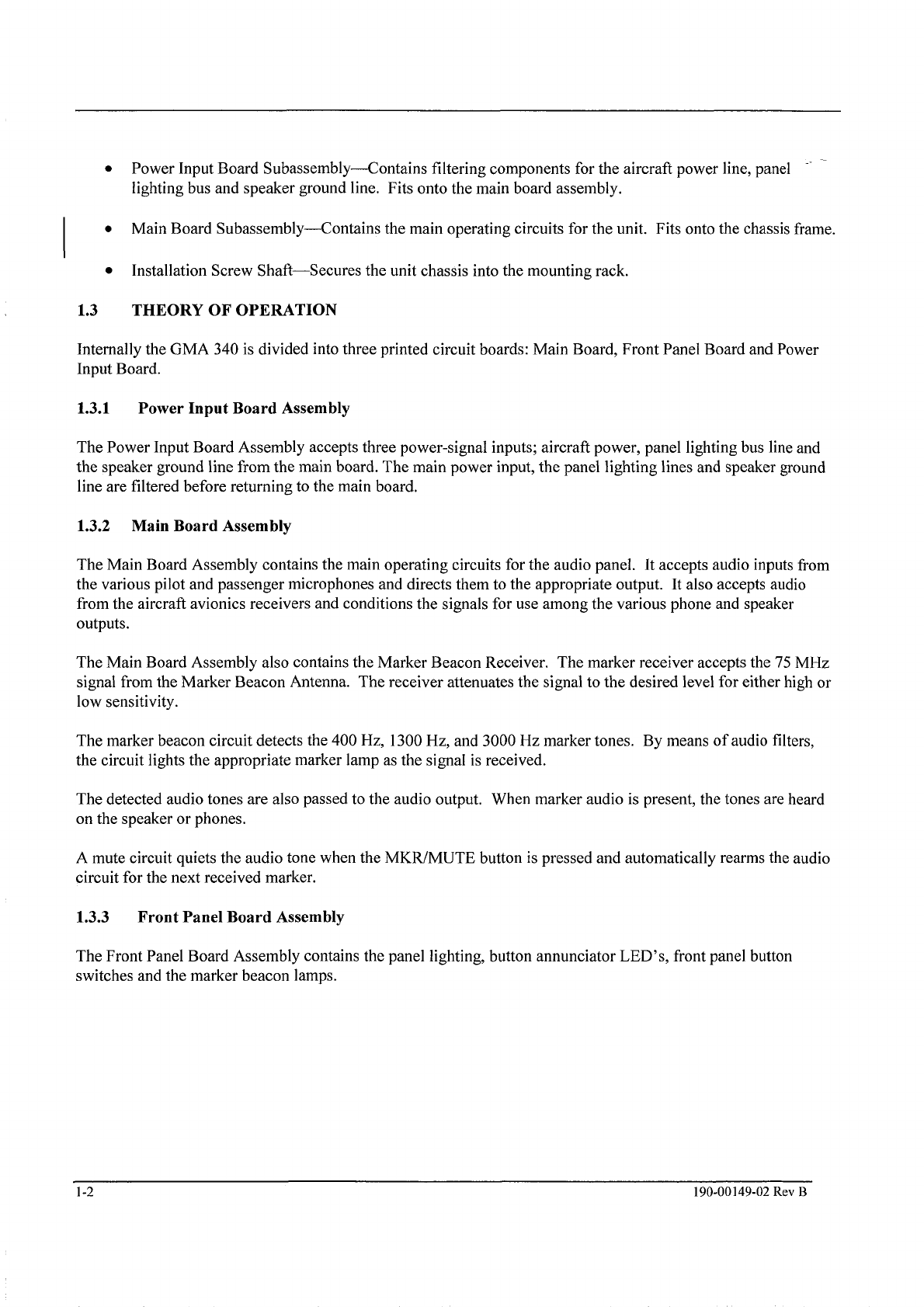
Power Input Board Subassembly-Contains filtering components for the aircraft power line, panel
lighting bus and speaker ground line. Fits onto the main board assembly.
0
Main Board Subassembly-Contains the main operating circuits for the unit. Fits onto the chassisframe.
Installation Screw Shaft-Secures the unit chassis into the mounting rack.
0
1.3
THEORY
OF
OPERATION
Internallythe GMA 340 is divided into three printed circuit boards: Main Board, Front Panel Board and Power
Input Board.
1.3.1 Power Input Board Assembly
The Power Input Board Assembly accepts three power-signal inputs; aircraft power, panel lightingbus line and
the speaker ground line from the main board. The main power input, the panel lighting lines and speaker ground
line are filtered before returning to the main board.
1.3.2 Main Board Assembly
The Main Board Assembly contains the main operating circuits for the audio panel. It accepts audio inputs from
the various pilot and passenger microphones and directs them to the appropriate output. It also accepts audio
from the aircraft avionics receivers and conditions the signals for use among the various phone and speaker
outputs.
The Main Board Assembly also contains the Marker Beacon Receiver. The marker receiver accepts the
75
MHz
signal from the Marker Beacon Antenna. The receiver attenuates the signal to the desired level for either high or
low sensitivity.
The marker beacon circuit detects the 400
Hz,
1300
Hz,
and 3000 Hz marker tones. By means of audio filters,
the circuit lights the appropriate marker lamp as the signal is received.
The detected audio tones are also passed to the audio output. When marker audio
is
present, the tones are heard
on the speaker or phones.
A mute circuit quiets the audiotone when the MKWMUTE button is pressed and automatically rearms the audio
circuit for the next received marker.
1.3.3 Front Panel Board Assembly
The Front Panel Board Assembly contains the panel lighting, button annunciator
LED’S,
front panel button
switches and the marker beacon lamps.
1-2
190-00149-02
Rev
B
The document reference is online, please check the correspondence between the online documentation and the printed version.
SECTION
2
SPECIALTEST EQUIPMENT
2.1 INTRODUCTION
This section describes special test equipment required for testing the GMA 340 Audio Panel. The Test Panel and
associated cables identified in this section may be fabricated locally accordingto the diagrams and parts
information given. Standard test equipment is listed in Section
5,
TESTING. For any questions regardingthe
operation of the special test equipment listed in this section, contact the GARMIN Product Support Department
at the address or telephone number given in Section
1.
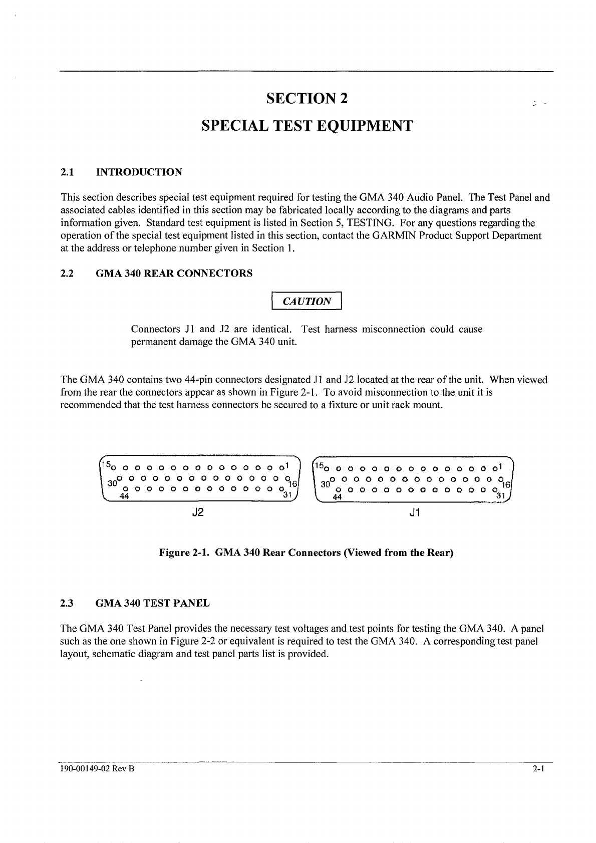
2.2 GMA340 REAR CONNECTORS
Connectors J1 and 52 are identical. Test harness misconnection could cause
permanent damage the GMA 340 unit.
The GMA 340 contains two 44-pin connectors designated J1 and 52 located at the rear of the unit. When viewed
from the rear the connectors appear as shown in Figure 2-1.
To
avoid misconnection to the unit it is
recommended that the test harness connectors be secured to a fixture or unit rack mount.
000000000000000
OOOOOOOOOOOOOO
44
44
J2
J1
Figure 2-1. GMA 340 Rear Connectors (Viewed from the Rear)
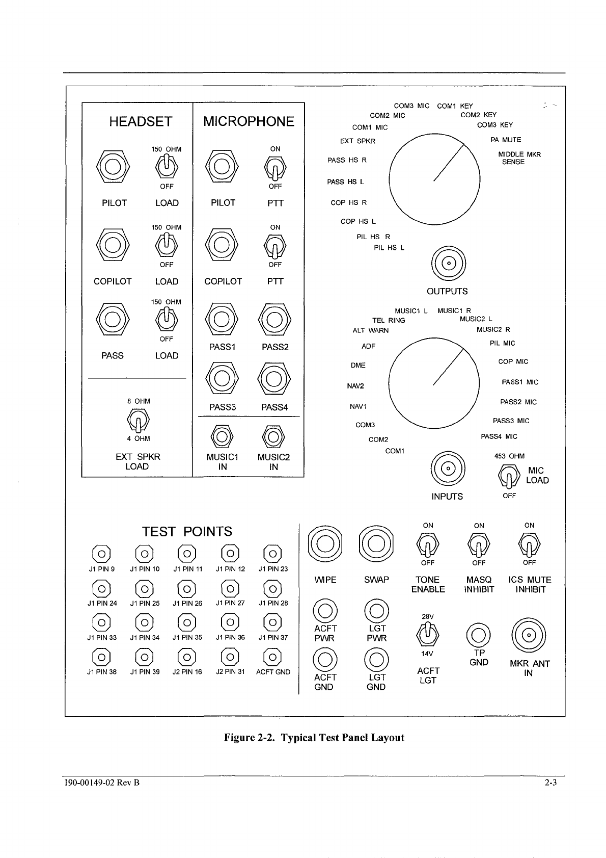
2.3 GMA340 TEST PANEL
The GMA 340 Test Panel provides the necessary test voltages and test points for testing the GMA 340. A panel
such as the one shown
in
Figure
2-2
or equivalent is required to test the GMA 340. A correspondingtest panel
layout, schematic diagram and test panel parts list is provided.
190-00149-02
Rev B
2-1
The document reference is online, please check the correspondence between the online documentation and the printed version.
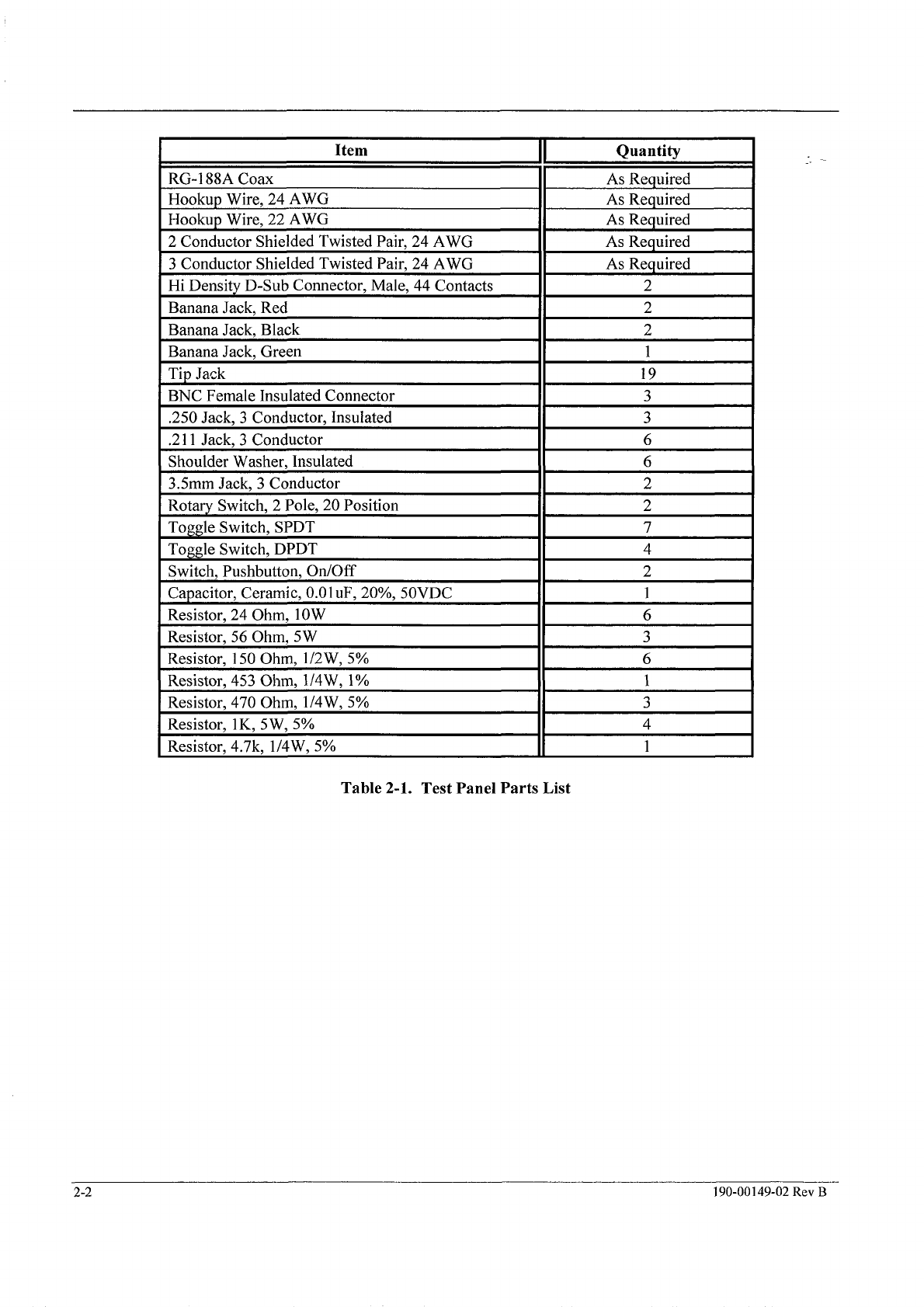
Item
RG-188A Coax
Hookup Wire, 24 AWG
Hookup Wire, 22 AWG
2 Conductor Shielded Twisted Pair, 24 AWG
3 Conductor Shielded Twisted Pair, 24 AWG
Banana Jack. Red
Hi Density D-Sub Connector, Male, 44 Contacts
Quantity
As Required
As Required
As Required
As Required
As Required
2
2
Rotary Switch,
2
Pole, 20 Position
Toggle Switch, SPDT
Toggle Switch. DPDT
Banana Jack, Black
Banana Jack, Green
Tip Jack
BNC Female Insulated Connector
.250 Jack,
3
Conductor, Insulated
.2
11
Jack, 3 Conductor
Shoulder Washer, Insulated
3.5mm Jack. 3 Conductor
Switch, Pushbutton, On/Off
Capacitor, Ceramic, 0.01uF, 20%, SOVDC
2
1
19
3
3
6
6
2
I
Resistor. 24 Ohm. 1OW
II
6
I
Resistor, 470 Ohm, 1/4W,
5%
Resistor,
1K,
5W, 5%
Resistor, 4.7k, 1/4W, 5%
Resistor, 56 Ohm, 5W
Resistor, 150Ohm, 1/2W,5%
Resistor. 453 Ohm. 1/4W.
1%
3
4
1
~
Table
2-1.
Test Panel Parts List
2-2
190-00149-02
Rev
B
The document reference is online, please check the correspondence between the online documentation and the printed version.
HEADSET
PILOT
@
@
COPILOT
PASS
150
OHM
@
@
69
OFF
LOAD
150
OHM
OFF
LOAD
150
OHM
OFF
LOAD
8 OHM
EXT SPKR
LOAD
J1
PIN
9
6)
(3
@
J1
PIN24
J1
PIN33
J1
PIN38
MICROPHONE
@
PILOT
COP1LOT
PASS1
PASS3
ON
@
OFF
@
OFF
@
@
PTT
ON
PTT
PASS2
PASS4
@@
MUSlCl MUSIC2
IN IN
TEST
POINTS
@@@
J1
PIN
10
J1
PIN
11
J1
PIN
12
J1
PIN
25
J1
PIN
26
J1
PIN27
J1 PIN 34
J1
PIN
35
J1
PIN 36
@@a
J1
PIN 39
J2
PIN
16
J2
PIN
31
J1
PIN23
@
@
(3
J1
PIN
28
J1
PIN37
ACFT GND
COM3 MIC COMI KEY
COMI MIC COM3 KEY
COM2 KEY
COM2 MIC
PA MUTE
MIDDLE MKR
SENSE
EXT SPKR
PASS HS R
PASS
HS
L
COP HS R
COP HS L
PIL
HS
R
HS
@
OUTPUTS
MUSlCl L MUSlCl R
TEL RING MUSIC2 L
ALT WARN MUSIC2 R
PIL MIC
COP MIC
PASS1 MIC
NAV2
PASS2 MIC
NAV’
PASS3 MIC
COM3 PASS4 MIC
COM2
COMI
(@
‘5
LOADMIC
WIPE
0
0
ACFT
PWR
ACFT
GND
INPUTS
ON ON
OFF OFF
SWAP TONE MASQ
ENABLE INHIBIT
PWR
0
LGT
GND
28V
14V
TP
GND
ACFT
LGT
OFF
ON
@
OFF
ICS MUTE
INHIBIT
MKR ANT
IN
Figure
2-2.
Typical Test Panel
Layout
190-00149-02
Rev
B
2-3
The document reference is online, please check the correspondence between the online documentation and the printed version.

1.
Proper insulation and grounding ofjacks, plugs, switches, and shielded wires is required to avoidaudio
signal ground loops.
2.
To
ensure proper shieldingand grounding, the test panel should be housed in a conductive metal enclosure.
It is critical that all hardware be electrically isolated from the test panel chassis to avoid audio ground loops.
3. Unless otherwise noted, all wires used in the test panel are 24 AWG.
4. Aircraft power leads should be as short as possible and routed near the test panel faceplate. Use 22 AWG
wire for the connections from 52 pins
8
through 11to the test panel ACFT PWR and ACFT GND banana
jacks.
5.
Use
a
minimal length of RG-188A coax cable or equivalent from the test panel MKR
IN
connector to 51
pins 1and 2.
6.
All two and three conductor shieldedwires must have shields terminated at one end only. The other end
must be left floating from ground.
7.
Shielded wires for the harness from the test panel to the unit under test should be terminated
to
the
respective
J1
and 52 connector backshells.
8.
Use Belden wire #83318and #83333 or equivalent for two and three conductor shielded pairs respectively.
9.
Both rotary switches have a dedicated BNC connector for convenient connection to the test equipment.
Deck “A” common of each rotary switch is wired to the appropriate BNC center conductor. Deck
“B”
common of each rotary switch is wired to the appropriate BNC outer conductor.
10. The TP GNDjack is the single point ground connection between the test panel and the power supply.
Shielded wires within the test panel may terminate to any point on the test panel chassis.
1
1.
The wiring harness from the test panel to the unit under test should be as short as possible for convenient
testing of the GMA 340.
12. Test panel labeling may be altered to accommodate the GMA 340 Dual ADF. Regardless of labeling, all
functions will be tested on all versions of the unit.
2.4
TEST HARNESS,
J1
AND
52
PIN ASSIGNMENTS
The following table provides pin assignment information for connectors
J
1and 52 test harness construction. The
test harness, an integral part of the test panel, is similar to connections in an aircraft.
2-4
190-00
149-02
Rev
B
The document reference is online, please check the correspondence between the online documentation and the printed version.

Pin
#
11
Connector J1
1
2
3
4
5
6
7
8
9
10
11
12
13
14
15
16
17
18
19
20
21
22
23
24
25
26
27
28
29
30
31
32
33
34
35
36
37
38
39
40
41
42
43
44
Mkr Ant
Mkr Ant Gnd
Corn
3
In
Corn
3
Gnd
Corn
3
Mic
Corn
3
Key
ADF In (ADF
2
In)
ADF Gnd (ADF
2
Gnd)
Corn
1
In
Corn
1
Gnd
Corn
1
Mic
Corn
1
Key
Corn
2
In
Corn
2
Gnd
Corn
2
Mic
MASQ Inh
Nav
1
In
Nav
1
Gnd
Nav
2
In
Nav
2
Gnd
DME In (ADF
1
In)
DME Gnd(ADF
1
Gnd)
Corn
3
Spkr Load
Corn
3
Spkr Load Gnd
Corn
1
SpkrLoad
Corn
1
Spkr Load Gnd
Corn
2
Spkr Load
Corn
2
Spkr Load Gnd
NC
Corn
2
Key
Pilot Headset R
Alt Wrn Gnd
Pilot Mic In
Pilot Mic Key
Pilot Mic Gnd
Ext White Lamp; A
Ext Blue Lamp;
0
Ext Amber Lamp; M
Middle Mkr Sens
Pass Headset L
Pass Headset R
Pass Headset Gnd
Tel Ringer Gnd
Tel Ringer In
Connector52
Pilot Headset Gnd
CO-PilotHeadset Gnd
CO-PilotHeadset L
CO-Pilot Headset R
14V
Lgt
LoI28V
Lgt Lo
14VLgtl28V
Lgt Lo
14VLgtf28V
Lgt
Aircraft Power
Aircraft Power
Aircraft Ground
Aircraft Ground
PA Mute
ICS Mute Inhibit
ICS Mute Inhibit Return
NC
Pilot Headset L
8
Ohm Select
Reserved
Tone Enable
Swap
Swap Return
NC
Music
1
L In
Music
1
RIn
Music
1
Gnd
Music
2
L In (NC)
Music
2
R In (DME In)
Music
2
Gnd (DME Gnd)
NC
Corn
TX
Mute
Pilot Headset
R
CO-PilotMic In
CO-PilotMic Key
CO-PilotMic Gnd
Pass
1
Mic
Pass
1
Mic Gnd
Pass
2
Mic
Pass
2
Mic Gnd
Pass
3
Mic
Pass
3
Mic Gnd
Pass
4
Mic
Pass
4
Mic Gnd
SpkrGnd
Spkr Out
Table 2-2. J1 and 52 Pin Assignments (Dual ADF in Parentheses)
190-00149-02
Rev
B
2-5
The document reference is online, please check the correspondence between the online documentation and the printed version.
311
1
MKR
ANT IN
ADF
In
(ADF 2
In)
w
,I
DME
In
(ADF 1
In)
TIP
@jK
JZ
1
14VLgt L0/2BV Lgt Lo
14VLgff28VLgt Lo
ACFT
PWR
ACFT
GND
ICS Mute Inhibit
ICS Mute InhibitReturn
Music2
R
(DME
In)
Music
2
Gnd
(DME
Gnd)
Pass
1
Mic
Gnd
Pass2
Mic
Gnd
Pass
3
Mic
Gnd
Pass4
Mic
Gnd
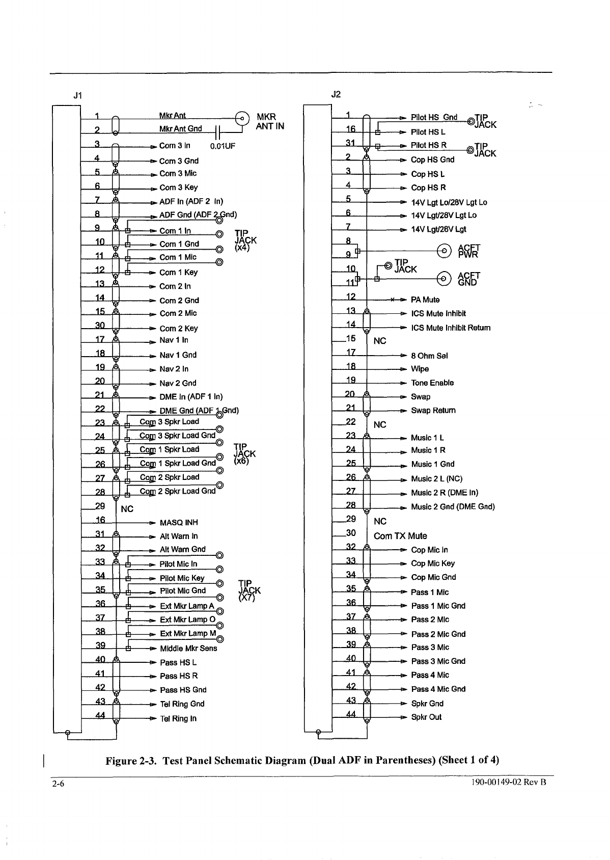
Figure
2-3.
Test Panel Schematic Diagram (Dual ADF
in
Parentheses) (Sheet
1
of
4)
2-6
190-00
149-02
Rev
B
The document reference is online, please check the correspondence between the online documentation and the printed version.

HEADSET
LOADSWITCHES
U
/\
A
E-
Pilot
HS
R
I-
f*{
-
Pass
bund
I
PassHS
L
E-
Pass
HS
R
UA
Pass
1
Mic
PASS
1
MIC
Pass
3
Mic
Gnd
Pass
3
Mic
PASS
3
MIC
PILOT
PlT
Iv
PilotMlc
Gnd
PilotMic
In
Pilot Mic
Kev
PIL
T
MI8
COPILOT PTT
I----
lb_
Cop Mic
Gnd
Cop Mic
In
Cop Mic
Key
COPILOT
MIC
ACFT LGT
SELECT
14VLgt LoI28V LgtLo
d-\
14VLgtl28VLgtLo
14v
14VLgtl28V Lgt LGT
Music2 Gnd
s
Music2
L
Music2
R
MUSIC
2
IN
Pass2 Mic
g$gs
2
Pass4 Mic
Gnd
Music1
Gnd
A
Pass4 Mic
A
Music1R
PASS
4
MUSIC
1
MIC
IN
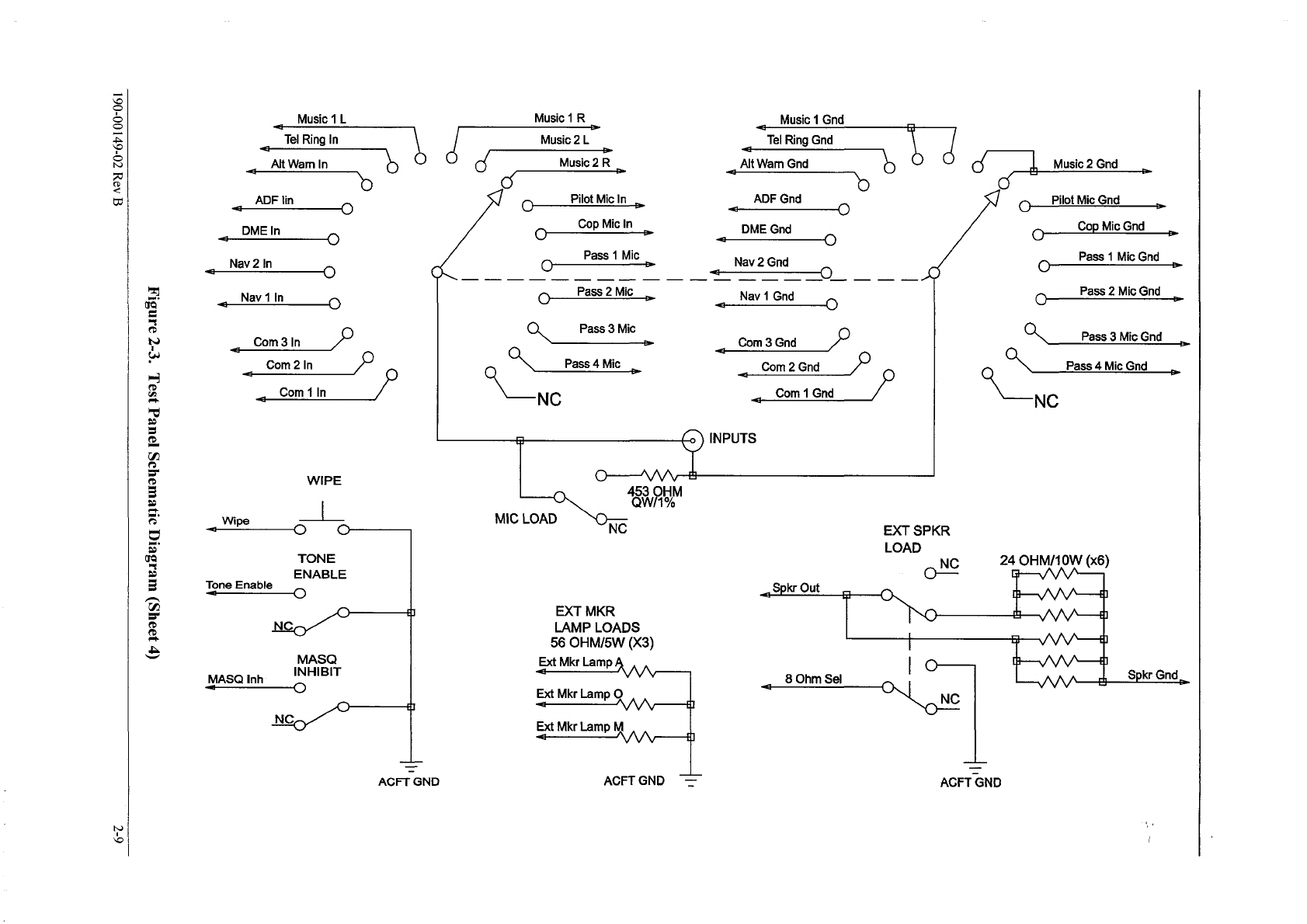
Figure
2-3.
Test Panel Schematic Diagram (Sheet
2)
190-00149-02
Rev
B
2-1
The document reference is online, please check the correspondence between the online documentation and the printed version.

,Corn
3
Mic
,Corn
2
Mic
,Corn
1
Mic
I
1-
Middle MkfSens@
flu&
Spkr
Gnd
0
A
0-NC
0-NC
-NC
ACFT
GND
TP
GND
SWAP
Swap
oio
SwapReturg
ICS
MUTE
INHIBIT
0
ICSMute Inhibit
ICS
Mute Inhibit Return
NOTE:
All
loadsare
QW/5%
unlessotherwisenoted.
-
ACFT-GND
TP
CHASSIS
The document reference is online, please check the correspondence between the online documentation and the printed version.
Music
1
L
Tel Ring
In
Pb
ADF lin
<
0
DME In
0
0
Nav
2
In
NavlIn
0
n
h
Corn
3
In
7,
Corn
2
In
Corn
1
In
/
WIPE
*
o---
Wipe
TONE
ENABLE
Tone
Enable
MASQ
INHIBIT
0
MASQ
Inh
b
I
-I
-
-
ACFT
GND
Music 1R Music
1
Gnd
-
l-9
L"
I
Music
2
L
-
e
Music
2
R
Tel RingGnd
At
Wam Gnd
b
PilotMic
In
ADF Gnd
DME Gnd
Nav
2
Gnd
Cop Mic In
-
Pass
1
Mic
Pass
4
Mic
MICLOAD
EXT
MKR
LAMP
LOADS
56
OHM/5W
(X3)
Ext
Mkr Lamp
1
ACFTGND
PilotMicGnd
Cop
MicGnd
Pass
1
MicGnd
0
Pass
2
MicGnd
Pass
3
MicGnd
Pass4MicGnd
'NC
EXT
SPKR
LOAD
24
OHMllOW
(x6)
KzzL
I
I
I
-
U
Spkr Gnd
9"
8
Ohm
Sel
-
ACFTGND
The document reference is online, please check the correspondence between the online documentation and the printed version.
(
'-.
C
(7AX CALiLE
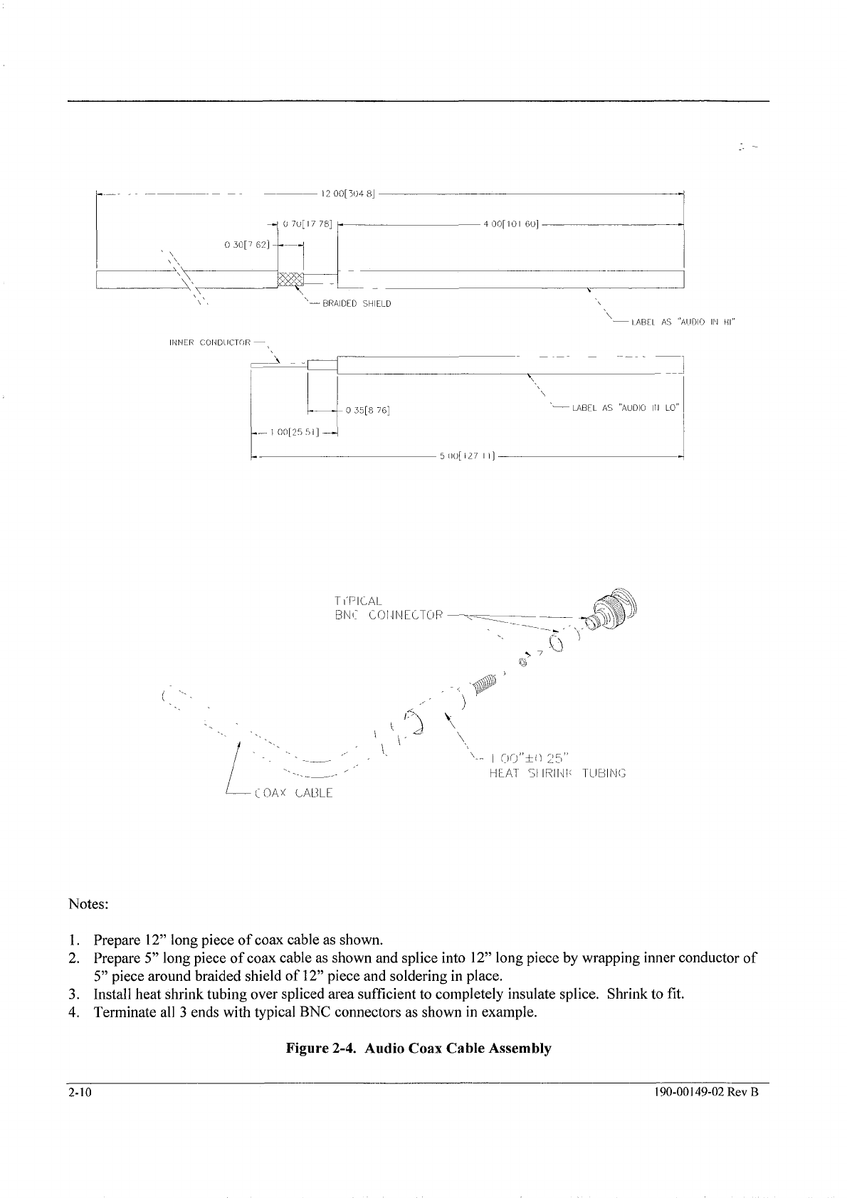
Notes:
1.
Prepare
12"
long piece of coax cable as shown.
2.
Prepare
5"
long piece of coax cable as shown and splice into
12"
long piece by wrapping inner conductor
of
5"
piece around braided shield of
12"
piece and soldering in place.
3.
Install heat shrink tubing over spliced area sufficient to completely insulate splice. Shrinkto fit.
4.
Terminate all
3
ends with typical BNC connectors as shown in example.
Figure
2-4.
Audio
Coax
Cable Assembly
2-10
190-00149-02
Rev
B
The document reference is online, please check the correspondence between the online documentation and the printed version.

SECTION
3
TROUBLESHOOTING
Individual components and assemblies in the GMA 340 Audio Panel can be
damaged by ESD (Electrostatic Discharge). Observe proper ESD procedures
when troubleshooting the unit.
3.1
TROUBLESHOOTING
This section contains information to aid in troubleshooting the GMA 340 to the replaceable assembly level. In
general, entry into the troubleshooting section occurs after
a
failure in the testing section. The type
of
failure
found in the test procedure determines the correct troubleshooting procedure. After the faulty module
is
isolated
and repair is made, the unit should be retested using the functional test procedure in Section
5,
TESTING of this
manual to ensure that the repaired area is operating correctly and that other areas have not been damaged during
the repair procedure.
3.2
TROUBLESHOOTING PROCEDURES
This troubleshooting guide
is
designed to allow isolation of malfunctions to the power input board or the front
panel subassembly. These checks reference specific tests in Section
5,
TESTING
of
this document. Referring to
the disassembly section, remove the top and bottom covers to perform the checks in the following paragraphs.
For tests not covered in this section, the entire unit must be returned to the factory for repair and return to service.
Figures 3.1, 3.2 and 3.3 are provided for connector location, pin numbering orientation and pin function.
190-00
149-02
Rev
B
3-
I
The document reference is online, please check the correspondence between the online documentation and the printed version.

no
0
0
0
=:O
0
000
00
ono
00
000
=:
00
0000
Figure 3.1. Front Panel Rear View, Connector J1 and 52 Location
Front Panel
Pin
1=:-1
I
Pilot
II
J1
Pin
22
I
I
CREW
II
J1
Pin
23
I
I
TEST
II
J1
Pin
18
I
Table 3.1. Front Panel Connector Detail (Dual ADF in Parentheses)
3-2 190-00149-02
Rev
B
The document reference is online, please check the correspondence between the online documentation and the printed version.
Other manuals for GMA 340
4
This manual suits for next models
3
Table of contents
Other Garmin Stereo System manuals

Garmin
Garmin FUSION MS-RA210 User manual

Garmin
Garmin Meteor 300 User manual

Garmin
Garmin GMA 342 User manual

Garmin
Garmin Fusion Apollo RA770 User manual

Garmin
Garmin Fusion Apollo MS-RA770 User manual

Garmin
Garmin FUSION User manual

Garmin
Garmin GMA 340 Owner's manual

Garmin
Garmin FUSION Apollo MS-WB670 User manual

Garmin
Garmin Fusion APOLLO RV-RA770 User manual

Garmin
Garmin Fusion MS-BB100 User manual


