Garmin GMA 340 Owner's manual

P/N 11934-S01 1 of 10
Cirrus Design Section 9
SR20 Supplements
Pilot’s Operating Handbook and
FAA Approved Airplane Flight Manual
Supplement
for
Garmin GMA 340 Audio System
Includes Optional XM Radio System
When the Garmin GMA 340 Audio Panel and the optional XM Radio
System are installed in the Cirrus Design SR20, this Supplement is
applicable and must be inserted in the Supplements Section (Section
9) of the Cirrus Design SR20 Pilot’s Operating Handbook (Handbook).
Information in this supplement either adds to, supersedes, or deletes
information in the basic Handbook.
• Note •
This POH Supplement Revision dated Revision 1: 07-18-05
supersedes and replaces the original issue of this supplement
dated 07-03-04. This revision adds required data for the
optional XM Radio System available for the Garmin GMA 340.
Revision 1: 07-18-05

2 of 10 P/N 11934-S01
Section 9 Cirrus Design
Supplements SR20
Figure - 1
Section 1 - General
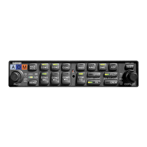
This supplement provides detailed operating instructions for the
Garmin GMA 340 Audio Selector Panel/Intercom System with internal
Marker Beacon. This supplement covers the basic operating areas of
the Audio Control Panel.
• Power On / Fail-safe Operation
• Audio / Transceiver Selection
• Speaker Output
• Public Address (PA) Function
• Personal Music Inputs
• Intercom (ICS)
• Marker Beacon
1. Marker Beacon Annunciators
2. Marker Audio Select Button / LED
3. Marker Sensitivity Select Button
a. HI Sensitivity LED
b. LO Sensitivity LED
4. Pilot Intercom Squelch (outer knob)
5. Power / Intercom Volume (inner knob)
6. Transceiver Audio Select Buttons/
LEDs
7. Photocell
8. Receiver Audio Select Buttons / LEDs
9. Transceiver Audio/Transmit Select
Buttons / LEDs
10. Split COM Button / LED
11. Cabin Audio Select Buttons / LEDs
a. SPKR, Cabin Speaker
b. PA, Public Address
12. Intercom Isolation Buttons / LEDs
a. PILOT Intercom Mode
b. CREW Intercom Mode
13. Copilot / Passenger Intercom
Squelch (outer knob)
14. Copilot (IN) / Passenger (OUT)
Intercom Volume (inner knob)
15. Indicator Test Button
141312
11
10
9
345
15
8
7
62
1
SR20_FM09_1108
Audio Control Panel
Revision 1: 07-18-05

P/N 11934-S01 3 of 10
Cirrus Design Section 9
SR20 Supplements
Section 2 - Limitations
Use of auxillary AUDIO IN entertainment input and the optionally
installed XM Radio System is prohibited during takeoff and landing.
Section 3 - Emergency Procedures
In the event of an audio panel power failure, the audio system will
revert to COM 1 for the pilot’s mic and headphones and the pilot will
have transmit and receive capability.
Section 4 - Normal Procedures
Refer to Section 7 - System Description in this supplement for a
complete description and operation of the Audio Control Panel.
Section 5 - Performance
No change from basic Handbook.
Section 6 - Weight & Balance
Garmin GMA 340 Audio System: No change from basic Handbook.
Installation of the optional XM Radio System adds the following
optional (Sym = O) equipment at the weight and arm shown in the
following table.
Section 7 - System Description
Power On and Fail-safe Operation
The Audio Control Panel is powered ‘OFF’ when the left inner knob
(PILOT) is at the full CCW (counter-clockwise) position. Rotating the
knob CW (clockwise) activates the unit. CW rotation of knob beyond
the ‘on’ detent increases pilot ICS (intercom system) volume.
ATA /
Item Description Sym Qty Part Number Unit
Wt Arm
22-01 XM Receiver O 1 16665-001 1.7 114.0
Revision 1: 07-18-05

4 of 10 P/N 11934-S01
Section 9 Cirrus Design
Supplements SR20
A fail-safe circuit connects the pilot’s headset directly to the COM1
transceiver in the event of a power failure to the audio control panel or
the panel is switched ‘OFF.’
Test
Pressing the TEST button illuminates all Panel LEDs and the Marker
Beacon Annunciators full bright. During normal operation, a photocell
mounted at the approximate center of the control panel senses
ambient light to allow automatic LED and annunciator intensity
adjustment. Nomenclature dimming is controlled by the INST lights
control on the instrument panel bolster.
Audio/Transceiver Selection
Audio selection is performed through the eight selector push buttons in
the center of the Audio Control Panel. All audio selector push buttons
are push-on, push-off. Selecting an audio source supplies audio to the
headphones or cabin speaker. Selected audio sources are indicated
by illumination of the push-button switch.
Navigation receiver audio source is selected by depressing NAV1,
NAV2 (if installed), MKR, DME (if installed), or ADF (if installed) will
select that radio or device as the audio source. Audio level of
navigation receivers is controlled through the selected radio volume
control.
Transceiver audio is selected by depressing COM1, COM2, or COM3
(if installed). When the audio source is selected using the COM1,
COM2, and COM3 buttons, the audio source will remain active
regardless of which transceiver is selected as the active MIC source.
Both transceiver audio and MIC (microphone) can be selected by
depressing COM1 MIC, COM2 MIC, or COM3 MIC (if installed). Both
pilot and copilot are connected to the selected transceiver and both
have transmit and receive capabilities. Pilot and copilot must use their
respective Push-To-Talk (PTT) switch to transmit. The intercom will
function normally. During transmissions the active transmitter’s COM
MIC button LED blinks at a 1 Hz rate indicating active transmission.
Split COM Function
Pressing the COM 1/2 button activates the split COM function. When
split COM is active, COM 1 is the pilot mic/audio source and COM2 is
Revision 1: 07-18-05

P/N 11934-S01 5 of 10
Cirrus Design Section 9
SR20 Supplements
the copilot mic/audio source. The pilot has receive and transmit
capabilities on COM1 and the copilot has receive and transmit
capabilities on COM2. While split COM is active, simultaneous
transmission from COM1 and COM2 is not possible. The pilot and
copilot can still listen to COM3, NAV1, NAV2, DME, ADF, and MKR.
Pressing the COM 1/2 button a second time will deactivate the split
COM function. While split COM is active, the copilot is able to make PA
announcements over the cabin speaker allowing the pilot to continue
using COM1 independently. This is accomplished by depressing the
PA button while split COM is active. Pressing the PA button a second
time deactivates this feature and returns the system to normal split
COM as described above.
COM Swap Mode
COM swap mode is not available in this installation.
Speaker Output
Pressing the SPKR button will cause the selected airplane radios to be
heard over the cabin speaker. Speaker output is muted when a COM
microphone is keyed. Speaker level is adjustable through an access
hole in the top of the unit (refer to Garmin installation manual or AMM).
Public Address (PA) Function
Pressing the PA button on the audio control panel activates the PA
function. When PA is activated and either the pilot’s or copilot’s
microphone is keyed (PTT pressed), the corresponding mic audio is
output over the cabin speaker. If the SPKR button is also active, any
previously active speaker audio will be muted while the microphone is
keyed. Pilot and copilot PA microphone speaker levels are adjustable
through an access hole in the top of the unit (refer to Garmin
installation manual or AMM).
Personal Music Inputs
• Note •
Serials 1005 thru 1532 and serials before SB 2X-34-14; Audio
from AUDIO INPUT jacks Music1 and Music2 is muted during
intercom activity.
Revision 1: 07-18-05

6 of 10 P/N 11934-S01
Section 9 Cirrus Design
Supplements SR20
The Audio Control Panel has provisions for up to two separate
personal entertainment input (music) devices. These devices are
plugged into the AUDIO INPUT jacks in the center console jack
panels. Music1 is connected at the AUDIO INPUT jack near the
convenience outlet. Music2 is connected to the jack on the aft console.
Music1 is soft-muted during all airplane radio activity. Music1 and
Music2 have characteristics affected by the active ICS isolation mode.
• Pressing the PILOT ICS Isolation button isolates the pilot from
the copilot and passengers. Music1 is available to copilot and
passengers.
• Pressing the CREW ICS Isolation button isolates the crew from
the passengers and allows the pilot and copilot to listen to
Music1 and the passengers to listen to Music2. Radio activity,
MKR activity, and pilot or copilot ICS activity will mute Music1.
Music2 is not muted.
• When both the PILOT and CREW ICS Isolation mode are not
selected, Music1 is available to crew and passengers. Radio
activity and MKR activity will mute Music1.
Intercom
Intercom controls are located towards the left side of the Audio Control
Panel. The controls consist of a Volume control for the pilot and
copilot, a Squelch control for all occupants, and an Intercom Mode
Selector switch.
Volume & Squelch Control
ICS volume and voice operated relay (VOX) squelch control is
controlled through the left (PILOT) and right (COPILOT) control knobs
on the Audio Control Panel Control. Knob control is as follows:
•Left Inner Knob – On/Off power control and pilot ICS volume.
Full CCW is ‘OFF’ position (click).
•Left Outer Knob – Pilot ICS mic VOX level. CW rotation
increases the amount of mic audio (VOX level) required to
break squelch. Full CCW is the ‘hot mic’ position.
•Right Inner Knob – When pushed in, rotation controls copilot
ICS volume. When out, rotation controls passenger ICS
volume.
Revision 1: 07-18-05

P/N 11934-S01 7 of 10
Cirrus Design Section 9
SR20 Supplements
•Right Outer Knob – Copilot and passenger mic VOX level. CW
rotation increases the amount of mic audio (VOX level) required
to break squelch. Full CCW is the ‘hot mic’ position.
Each microphone input has a dedicated VOX circuit to assure that only
the active microphone(s) is/are heard when squelch is broken. After
the operator has stopped talking, the intercom channel remains
momentarily open to avoid closure between words or normal pauses.
Control
The Audio Control Panel provides an adjustable Voice Operated Relay
(VOX) Squelch Control for the pilot, copilot, and passengers. Since the
VOX circuits reduce the number of microphones active at any one
time, the amount of unwanted background noise in the headphones is
diminished. This also allows the use of dissimilar headsets with the
same intercom. Because the user can adjust the trip level of the VOX
squelch to fit the individual voice and microphone, this helps eliminate
the frustration of clipping the first syllables. There is a slight delay after
a person stops talking before the channel closes. This prevents
closure between words and eliminates choppy communications.
To adjust squelch:
1. With the engine running, set the VOX trip level by slowly rotating
the SQL control knob clockwise until you no longer hear the
engine noise in the headphones.
2. Position microphone near your lips and speak into microphone.
Verify that normal speech levels open the channel.
Intercom Modes
The GMA 340 provides three intercom (ICS) modes to further simplify
workload and minimize distractions during all phases of flight: PILOT,
CREW, and ALL. The mode selection is accomplished using the
PILOT and CREW push-buttons. Pressing a button activates the
corresponding ICS mode and pressing the button a second time
deactivates the mode. The operator can switch modes (PILOT to
CREW or CREW to PILOT) by pressing the desired modes push-
Revision 1: 07-18-05

8 of 10 P/N 11934-S01
Section 9 Cirrus Design
Supplements SR20
button. ALL mode is active when neither PILOT or CREW have been
selected.
The following table shows, in abbreviated form, what each occupant
hears in each of the selectable Intercom modes:
Marker Beacon
The Marker Beacon Receiver provides visual and audio indicators to
alert the pilot when the airplane passes over a 75 MHz transmitter.
Marker beacon controls and lights are located at the extreme left of the
Audio Control Panel.
PILOT The pilot is isolated from the intercom. The pilot can hear
radio and sidetone only during radio transmissions. Copilot
and passengers can hear the intercom and music but not the
airplane radio receptions or pilot transmissions.
CREW Pilot and copilot are connected on one intercom channel and
have exclusive access to the aircraft radios. They may also
listen to Music1. Passengers can continue to communicate
with themselves without interrupting the Crew and also may
listen to Music2.
ALL All parties will hear the aircraft radio, intercom, and Music1.
The music volume increases gradually back to the original
level after communications have been completed. Both pilot
and copilot have access to the COM transceivers.
Mode Pilot Hears Copilot Hears Passenger Hears
PILOT A/C Radios
Pilot
Passengers
Copilot
Music1
Passengers
Copilot
Music1
CREW A/C Radios
Pilot/Copilot
Music1
A/C Radios
Copilot/Pilot
Music1
Passengers
Music2
ALL A/C Radio
Pilot/Copilot
Passengers
Music1
A/C Radio Pilot/
Copilot
Passengers
Music1
A/C Radio
Pilot/Copilot
Passengers
Music1
Revision 1: 07-18-05

P/N 11934-S01 9 of 10
Cirrus Design Section 9
SR20 Supplements
Marker beacon audio is selected by pressing the MKR push-button. If
no marker beacon signal is being received, pressing the MKR push-
button a second time deselects marker beacon audio. However, if
marker beacon is being received, pressing the MKR push-button a
second time will mute the audio but the light will continue to flash.
Pressing the MKR push-button a third time (while marker beacon
audio is muted) deselects marker beacon audio. Marker beacon audio
muting automatically disables when the current signal is no longer
received.
• Note •
The marker beacon lamps (O, M, A) operate independently of
the audio and cannot be disabled.
Marker beacon light and audio keying for ILS approach are
summarized below:
Marker Beacon Sensitivity
The SENS push-button on the left side of the panel is used to set the
marker beacon receiver sensitivity. The selected sensitivity level is
indicated by illumination of the HIGH or LOW LED. When HIGH
sensitivity is selected, the outer marker beacon tone will sound farther
out. Selecting LOW sensitivity at this point allows more accurate
location of the Outer Marker. Typically, HIGH sensitivity is selected
until the outer marker tone is heard, and then LOW sensitivity is
selected for more accurate outer marker location.
O (Blue) Outer Marker light and associated 400 Hertz tone. The
light and tone are keyed at a rate of two tones/flashes per
second.
M (Amber) Middle Marker light and associated 1300 Hertz tone. The
light and tone are keyed alternately with short and long
bursts.
A (White) Airway/Inner Marker light and associated 3000 Hertz
tone. The light and tone are keyed at a rate of six times
per second.
Revision 1: 07-18-05

10 of 10 P/N 11934-S01
Section 9 Cirrus Design
Supplements SR20
XM Radio System (Optional Installation)
• Note •
For a detailed operating instructions, refer to the XM Radio
Wireless Controller User Instructions, Document No.
XMC050-4, original release or later. MFD software
partnumber 530-00162-000 or later is required for installation
of XM Radio System.
Subscription to a XM Radio System Service Package is
required for operation. Contact XM Satellite Radio at
800.985.9200 for subscription information.
The optional XM Radio System provides satellite broadcast audio
entertainment and information to aircraft occupants via the Garmin
GMA 340 Audio System while traveling anywhere within the
contiguous United States of America.
The XM receiver, installed in the co-pilot side of the center console,
receives audio information via its integral antenna from two
geosynchronous XM broadcast satellites. The audio signal is then sent
by wire to the Audio Control Panel’s Music1 and Music2 AUDIO INPUT
jacks. System operation is provided by a hand held, wireless
controller.
• When initially powered, the XM radio volume is set to mute and
will remain muted until the XM radio establishes communication
with the wireless controller.
• System volume for both AUDIO INPUT jacks is controlled
simultaneously via the wireless controller.
• In the event of wireless controller failure during flight, cycling
the Weather/Stormscope circuit breaker will reset the volume to
mute.
• XM radio is the default audio heard on the AUDIO INPUT jacks.
If a personal entertainment device such as a CD player is
plugged into either AUDIO INPUT jacks, the external source will
override the XM audio signal. Refer to the Intercom Modes
Table presented above for a description of intercom modes.
The XM Radio System is powered by 28 VDC supplied through the 3-
amp Weather/Stormscope breaker on the Non-Essential Bus.
Revision 1: 07-18-05
Other manuals for GMA 340
4
Table of contents
Other Garmin Stereo System manuals
Garmin
Garmin Meteor 300 User manual
Garmin
Garmin Fusion Apollo MS-RA770 User manual
Garmin
Garmin Fusion APOLLO RV-RA770 User manual
Garmin
Garmin GMA 342 User manual
Garmin
Garmin Fusion Apollo SRX400 User manual
Garmin
Garmin FUSION MS-RA210 User manual

Garmin
Garmin Fusion Apollo RA770 User manual
Garmin
Garmin GMA 340 User manual

Garmin
Garmin Fusion MS-BB100 User manual
Garmin
Garmin FUSION User manual


