Garnet SEELEVEL 828 User manual

Printed in Canada
www.garnetinstruments.com
MODEL 828 MANUAL
Serial Interface

Page 2 828 Manual
Table of Contents
CHAPTER 1 - OVERVIEW.............................................................................................3
CHAPTER 2 - DESCRIPTION.......................................................................................4
CHAPTER 3 - INSTALLATION GUIDE.......................................................................7
CHAPTER 4 - SERIAL COMMANDS.........................................................................8
CHAPTER 5 - TROUBLESHOOTING GUIDE......................................................... 19
CHAPTER 6 - SERVICE AND WARRANTY INFORMATION............................ 20
MAIL IN WARRANTY ................................................................................................. 21
GARNET
SEELEVELTM
Serial Interface
MODEL 828
828 Manual_v7.2 - 04-Sep-2018

Page 3
828 Manual
CHAPTER 1 - OVERVIEW
Congratulations on purchasing the Garnet Instruments Model
828 SEELEVEL™ Serial Interface. The Model 828 is designed to
interface up to six 808P2/810PS2 displays or one 806B display to
a standard RS232 serial connection for data acquisition. This can
be connected to a remote computer, PLC or cellular modem and
an external printer can be attached to a second serial port to print
receipts for historical PTO events. There is a Power Take Off (PTO)
sense line to determine when transmitted data is required. This
prevents false readings from being transmitted while the truck is
moving.

Page 4 828 Manual
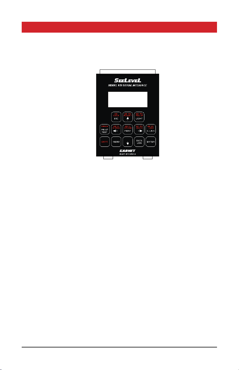
CHAPTER 2 - DESCRIPTION
The 828 has a 4x16 LCD display to congure the setup options,
verify connections, help with troubleshooting, and to display
the levels of the SEELEVEL™ gauges. The number of levels displayed
corresponds to the number of compartments congured.
Historical PTO events are saved to memory. These events log the
time and volume when a PTO is turned on and when the PTO is
turned off. The PTO events can be retrieved from memory through
the serial connection, or time stamped receipts can be printed
using a portable printer.
Many of the 828 keypad buttons require a ve digit numeric
password authentication before they can be used. The default
password is “11111”. Entering the last three characters ‘111’
correctly provides Level 1 Access which enables the CLOCK button.
Entering all ve digits correctly provides Level 2 Access allowing all
functions. The PRINT, LIGHT, VERSION, and DATALOG buttons are
always available. Access to Level 1 and 2 expires after 10 minutes.
The password can be changed using the Set Password Key serial
command. If in Geotab New (mode 2) the password “99991”
will provide access to the MENU button functionality to change
the mode back to ASCII (mode 0) so the Set Password Key serial
command could be used to reset the password.
Description of Keypad Buttons:
ENTER button: This button is used to store setup changes into
programmer memory.
ESC button: This is used to exit various menus.
button: This button is used to navigate through setup menus.
button: This button is used to navigate through setup menus.
button: This button is used to navigate through setup menus.
button: This button is used to navigate through setup menus.
PRINT button: Select a tank and historical PTO event to print and
send its level out the printer serial port .
LIGHT button: This turns the display backlight on and off.
SHIFT button: This button is used to select the button functions
printed in red. SHIFT must be held down while pressing the other
button.

Page 5
828 Manual
SET CLOCK+SHIFT button: Set the on board real time clock.
Use the up and down buttons to change the highlighted time/
date, and the sideways buttons to select which item to set. Use
the ENTER button to save the time and date shown, and exit the
menu. To exit the menu without saving, use the ESC button.
SET PTO POLARITY+SHIFT button: Select whether the PTO is
active when high or low polarity is present on the PTO wire. Use
the up and down buttons to change the selection. Use the ENTER
button to save the value shown, and exit the menu. To exit the
menu without saving, use the ESC button.
SET PTO PULLUP+SHIFT button: Select whether the PTO pull-up
is on or off. Use the up and down buttons to change the selection.
Use the ENTER button to save the value shown, and exit the menu.
To exit the menu without saving, use the ESC button.
SET PTO DELAY+SHIFT button: Sets the delay after the PTO is
engaged or disengaged before a serial data transmit is done. Use
the up and down buttons to change the value shown. Use the
sideways buttons to select the engage or disengage delay. Use
the ENTER button to save the value shown, “st” will be shown for a
couple of seconds to verify that the value has been stored. Once
the new values have been stored, use the ESC button to exit the
menu. Any changes made after pressing the ENTER button will
not be stored.
VERSION+SHIFT button: Shows the hardware and software
version of the 828.
SET NO. TANKS+SHIFT button: Set the number of compartments
to be monitored and displayed on the LCD screen for updates. This
should match the number of SEELEVEL™ gauges. Use the up and
down buttons to change the value shown. Use the ENTER button
to save the value shown, and exit the menu. To exit the menu
without saving, use the ESC button. Currently, 806 gauges can
only monitor compartment one. The 806 gauge must be viewing
compartment one to work.
SET TX INTERVAL+SHIFT button: Sets the interval between
automatic serial data transmissions of the levels shown on the
display. This can be from 1 to 99,999 seconds. Use the up and
down buttons to change the highlighted digit. Use the sideways
buttons to select a different digit. Use the ENTER button to save
the value shown, and exit the menu. To exit the menu without
saving, use the ESC button.

Page 6 828 Manual
SET TX IN OPTIONS+SHIFT button: Sets the transmit interval
options. The 828 can be congured to send or not send interval
updates during the time that the PTO is disengaged. Updates are
always sent during the time that the PTO is engaged. Use the up
and down buttons to change the selection. Use the ENTER button
to save the value shown, and exit the menu. To exit the menu
without saving, use the ESC button.
MENU button: Sets the 828 Mode and Gauge type. Use the up
button to set the 828 to 806 gauge viewing compartment one.
Use the down button to set the 828 to use 808 and 810 gauges.
Use the right and left buttons to select ASCII (mode 0), Geotab Old
(mode 1), or Geotab New (mode 2) serial transmit modes. Use ESC
button to exit.
In mode 0, which is the default, ASCII characters are sent out when
PTO changes occur, interval updates are sent, and compartment
data has been scanned.
In mode 1, Geotab’s RS232 Extended Data Message Format GO2/
GO3/GO4 is used when PTO changes occur and interval updates
are sent.
In mode 2, Geotab’s Third Party Data (Message Type 0x80) protocol
is used when PTO changes occur and interval updates are sent.
DATA LOG button: Send all the historical PTO events out the
serial port.
DATA LOG+ SHIFT button: Clear all historical PTO events from
memory.
Note that if one of the set menus is entered and there has been
no button pressed for one minute, the menu will automatically exit
without saving. This way the system cannot be accidentally left in
one of the set menus where it will not respond to serial data.
Page 7
828 Manual
CHAPTER 3 - INSTALLATION GUIDE
1. The 828 is not weatherproof. The connectors on the ends of
the 828 need to be clear of obstructions. Ensure that the unit
is mounted in an appropriate location.
2. The 828 needs to be supplied with +12VDC from the truck
through a 1 amp fuse along with a good chassis ground.
3. One signal wire needs to be fed from the truck’s PTO to the
PTO INPUT on the 828. This wire needs to either have an active
high or active low signal.
4. The six remote inputs allow a single 828 to communicate with
up to six different SEELEVEL gauges. Connect the remote outputs
from the SEELEVEL 806B, 806Bi, 808P2 or 810PS2 systems to
the REMOTE wire inputs on the 828. NOTE: The ground used
for the 828 has to be the same ground connection used for
the 806B, 808P2 or 810PS2.
5. Connect the serial data port to the serial device using a
standard 9 pin serial cable.
6. The serial port settings for both serial ports are 9600 baud, no
parity, 8 data bits, 1 stop bit ASCII communications.
Printer Tx
RS232Rx
RS232Tx
+12 VDC
Ground
PTO
Remote 1
Remote 2
Remote 3
Remote 4
Remote 5
Remote 6
Printer
Serial Port Serial Data
Port

Page 8 828 Manual
CHAPTER 4 - SERIAL COMMANDS
The following section describes the dened 828 serial commands.
The serial data requests are ASCII data strings. Throughout
this section <CR> represents a single carriage return character
(hexadecimal 0x0D). In this section Red text represents serial
data being received by the 828. Blue text represents serial data
being transmitted from the 828. Either uppercase or lowercase
characters can be used, the response will be in the case that is
used to make the request.
Set Password Key
‘k=11111’ sets the ve digit numeric password key.
k=11111<CR>
k,11111<CR>
Request Password Key
‘k’ requests the the ve digit numeric password key.
k<CR>
k,11111<CR>
Set Gauge Type (808/810 or 806)
Set the type of gauge connected to the 828. ‘g=0’ for 808 or 810,
‘g=1’ for 806.
808 or 810 806
g=0<CR> g=1<CR>
g,0<CR> g,1<CR>
Request Gauge Type (808/810 or 806)
‘g’ requests the type of gauge connected to the 828.
808 or 810 806
g<CR> g<CR>
g,0<CR> g,1<CR>
Currently, 806 gauges can only monitor compartment one. The
806 gauge must be viewing compartment one to work.

Page 9
828 Manual
Mode conguration
The 828 can be set up to operate in three modes of operation.
‘m=0’ sets mode 0, ‘m=1’ sets mode 1, and ‘m=2’ sets mode 2.
IMPORTANT NOTE: The 828 only accepts serial commands when
in mode 0 or 1. If the 828 is set to mode 2 via a serial command,
it can only be set back to mode 0 or 1 via the front keypad MENU
button.
m=0<CR> m=1<CR> m=2<CR>
m,0<CR> m,1<CR> m,2<CR>
In mode 0, which is the default, ASCII characters are sent out when
PTO changes occur, interval updates are sent, and compartment
data has been scanned.
In mode 1, Geotab’s RS232 Extended Data Message Format GO2/
GO3/GO4 is used when PTO changes occur and interval updates
are sent.
In mode 2, Geotab’s Third Party Data (Message Type 0x80) protocol
is used when PTO changes occur and interval updates are sent.
Request Mode
‘m’ requests the mode from the 828.
Mode 0 Mode 1
m<CR> m<CR>
m,0<CR> m,1<CR>

Page 10 828 Manual
PTO change (Mode 0)
During normal operations, a change of PTO status causes the 828
to send out a comma separated list of values corresponding to the
PTO status followed by the number of channels being monitored.
The transmit is done after a programmable delay.
p,E,11.16,79.00, 0.00, 0.00, 0.00, 0.00<CR>
The next example shows the PTO disengaged and only two
channels being monitored.
p,D,11.16,79.00<CR>
The next example shows the PTO engaged and all six compartments
having invalid data.
p,E,NOSIG,NOSIG,NOSIG,NOSIG,NOSIG,NOSIG<CR>
The level reading will always be ve characters including the
decimal place. If no decimal place is present a space character will
pad the least signicant byte. NOSIG shows no valid level data.
ERROR shows level data error.
PTO change (Mode 1)
During normal operations, a change of PTO status causes the 828
to send out a message compatible with Geotab’s “RS232 External
Data Message Format GO2/GO3/GO4”.
Byte Value Description
0STX 0x02
1 Message Type 1 0x01
2 Body Length (x) 1-27
3 to 2+x Data x byes of data, max of 30 bytes
3+x to
4+x
Checksum 2 byte checksum (big endian) of
bytes 0 to 2+x with 0x01 added
to each byte before summing
5+x ETX 0x03

Page 11
828 Manual
When the Geotab device receives the message the Geotab device
will send an acknowledge back on the serial port.
Byte Value Description
0STX 0x02
1ACK 0x06
2ETX 0x03
According to the Geotab’s “R232 External Data Message Format
GO2/GO3/GO4” documentation:
[When the Geotab device receives the 828 data], a log record
of type 38 will be saved to the [Geotab] ash containing the
last GPS date time. A log record type 39 will follow with the
same date/time as the type 38 log record providing additional
data.
To ensure compatibility with Geotab devices, only four channels
should be congured in the 828 when using Mode 1, since the
Body Length is limited to 27 characters.
The Data part of the message contains a comma separated list of
values corresponding to the PTO status followed by the number
of channels being monitored. The transmit is done after a
programmable delay.
E,11.16,79.00, 0.00, 0.00
The next example shows the Data part of the message with the
PTO disengaged and only two channels being monitored.
D,11.16,79.00
The next example shows the Data part of the message with the
PTO engaged and all four compartments having invalid data.
E,NOSIG,NOSIG,NOSIG,NOSIG
The level reading will always be ve characters including the
decimal place. If no decimal place is present a space character will
pad the least signicant byte. NOSIG shows no valid level data.
ERROR shows level data error.

Page 12 828 Manual
Set PTO conguration
There are four items to congure:
1. Resistor pullup on or off.
2. PTO engagement polarity high or low.
3. Transmit delay upon PTO disengagement.
4. Transmit delay upon PTO engagement.
‘u=1’ turns the PTO pullup on, ‘u=0” turns the PTO pullup off.
u=1<CR> u=0<CR>
u,1<CR> u,0<CR>
‘e=1’ means the PTO is engaged when the signal is high (+12V),
‘e=0’ means the PTO is engaged when the signal is low (ground).
e=1<CR> e=0<CR>
e,1<CR> e,0<CR>
‘w=0’ to ‘w=99’ sets the delay in seconds after the PTO has
disengaged before the level is read and transmitted. Numbers
larger than 99 will be ignored. This gives time for the liquid
agitation due to loading to settle. During this delay new gauge
values will be continue to be read. Once the delay expires, new
gauge values will be ignored.
w=0<CR> w=60<CR>
w,0<CR> w,60<CR>
‘x=0’ to ‘x=99’ sets the delay in seconds after the PTO has engaged
before the level is read and transmitted. Numbers larger than
99 will be ignored. This gives time for the liquid agitation due
to the trucking moving to settle. If the delay is set to 0, then
the stored values obtained when the PTO was disengaged will be
transmitted, since there will not have been any time to read the
new values from the gauges.
x=0<CR> x=60<CR>
x,0<CR> x,60<CR>

Page 13
828 Manual
Request PTO conguration
‘u’ requests the PTO conguration for the pullup.
Pullup turned on Pullup turned off
u<CR> u<CR>
u,1<CR> u,0<CR>
‘e’ requests the PTO conguration for the engagement polarity.
Engaged when high Engaged when low
e<CR> e<CR>
e,1<CR> e,0<CR>
‘w’ requests the delay in seconds after the PTO has disengaged
before the level is read and transmitted.
w<CR> w<CR>
w,0<CR> w,60<CR>
‘x’ requests the delay in seconds after the PTO has engaged before
the level is read and transmitted.
x<CR> x<CR>
x,0<CR> x,10<CR>
PTO status request
‘p’ requests the PTO status from the 828 where ‘E’ is PTO engaged
and ‘D’ is PTO disengaged.
Engaged Disengaged
p<CR> p<CR>
p,E<CR> p,D<CR>

Page 14 828 Manual
Scan all compartments (Mode 0)
‘s’ request a scan of all congured compartments. The 828 sends
out a comma separated list of values corresponding to the PTO
status followed by the number of channels being monitored.
s<CR>
s,D,11.16,79.00, 0.00, 0.00, 0.00, 0.00<CR>
s<CR>
s,E,11.16,79.00<CR>
Scan a specic compartment (Mode 0)
‘s1’ to ‘s6’ request a scan of a specic compartment. The 828 sends
out a value corresponding to the requested compartment.
s1<CR> s2<CR> s3<CR>
s1,11.16<CR> s2,79.00<CR> s3, 0.00<CR>
s4<CR> s5<CR> s6<CR>
s4, 0.00<CR> s5, 0.00<CR> s6, 0.00<CR>
Set Number of Compartments
‘c=1’ to ‘c=6’ sets the number of compartments to be monitored
and displayed on the LCD screen. This normally corresponds to
the number of SEELEVEL™ gauges connected. This value must be
from 1 to 6, any other number will be ignored. Any digits after
the rst one will be ignored. However, if some compartments are
not being used and the fastest possible update rate is desired, the
number of compartments can be set lower. Note, however, that as
the number of compartments is reduced, it is always the highest
numbered ones that are removed.
c=1<CR> c=6<CR>
c,1<CR> c,6<CR>
Currently, 806 gauges can only monitor compartment one. The
806 gauge must be viewing compartment one to work.
Request Number of Compartments
‘c’ reads the number of compartments being monitored and
displayed on the LCD screen. This normally corresponds to the
number of SEELEVEL™ gauges connected (see above).
c<CR> c<CR>
c,1<CR> c,6<CR>

Page 15
828 Manual
Set Update Interval (0=no automatic updates)
The 828 can be congured to automatically send updates on a
timed interval. The update interval is specied in seconds, the value
must be between 0 and 99,999 seconds. Values larger than 99,999
will be ignored. Within approximately one second of setting the
interval, the rst interval transmission will be done.
I=60<CR> I=7200<CR>
I,60<CR> I,7200<CR>
By setting the update interval to 0, automatic updates are turned
off.
I=0<CR>
I,0<CR>
Set Transmit Interval Options
The 828 can be congured to send or not send interval updates
during the time that the PTO is disengaged. Updates are always
sent during the time that the PTO is engaged.
Do send Do not send
o=1<CR> o=0<CR>
o,1<CR> o,0<CR>
Request Transmit Interval Options
Do send Do not send
o<CR> o<CR>
o,1<CR> o,0<CR>
Interval Update (Mode 0)
In Mode 0, when an auto update interval has been dened, the 828
sends out a comma separated list of values corresponding to the
PTO status followed by the number of channels being monitored
on the dened interval, followed by the time and date. The interval
is specied in seconds.
i,E,11.16,79.00, 0.00, 0.00, 0.00, 0.00,12:48:16AM Mar 23
2008<CR>
Interval Update (Mode 1)
In Mode 1, when an auto update interval has been dened, the 828
sends the same message previously dened in the PTO Change
(Mode 1) section of this document. The interval is specied in
seconds.

Page 16 828 Manual
Request Read PTO historical events
‘r’ requests a read of the PTO historical events. This includes the
volumes when the PTO was enabled ‘E’, disabled ‘D’, and the total
‘T’ product change based on the difference.
r<CR>
R,007,E, 4.00, 3:49:53PM Jan 14 2016<CR>
R,007,D,33.00, 3:50:07PM Jan 14 2016<CR>
T,007,+29.00, 3:50:07PM Jan 14 2016<CR>
R,006,E, 2.66, 5:46:04PM Jan 04 2016<CR>
R,006,D, 2.66, 9:37:51AM Jan 07 2016<CR>
T,006,+00.00, 9:37:51AM Jan 07 2016<CR>
R,005,E, 49.0, 5:40:24PM Dec 16 2015<CR>
R,005,D, 55.7, 5:11:09PM Jan 04 2016<CR>
T,005,+006.7, 5:11:09PM Jan 04 2016<CR>
R,004,E, 39.0, 6:23:58PM Dec 15 2015<CR>
R,004,D, 39.2, 6:24:10PM Dec 15 2015<CR>
T,004,+000.2, 6:24:10PM Dec 15 2015<CR>
R,003,E, 35.7, 6:22:33PM Dec 15 2015<CR>
R,003,D, 34.5, 6:21:55PM Dec 15 2015<CR>
T,003,-001.2, 6:21:55PM Dec 15 2015<CR>
R,002,E, 22.7, 6:21:11PM Dec 15 2015<CR>
R,002,D, 25.2, 6:21:21PM Dec 15 2015<CR>
T,002,+002.5, 6:21:21PM Dec 15 2015<CR>
R,001,E, 20.7, 6:20:46PM Dec 15 2015<CR>
R,001,D, 20.7, 6:20:52PM Dec 15 2015<CR>
T,001,+000.0, 6:20:52PM Dec 15 2015<CR>
Request Read PTO historical events with only the Totals
‘R’ requests a read of the PTO historical events, but only sends out
the total ‘T’ the product changed based on the diffence between
when the PTO was enabled and then the PTO was disabled.
R<CR>
T,007,+29.00, 3:50:07PM Jan 14 2016<CR>
T,006,+00.00, 9:37:51AM Jan 07 2016<CR>
T,005,+006.7, 5:11:09PM Jan 04 2016<CR>
T,004,+000.2, 6:24:10PM Dec 15 2015<CR>
T,003,-001.2, 6:21:55PM Dec 15 2015<CR>
T,002,+002.5, 6:21:21PM Dec 15 2015<CR>
T,001,+000.0, 6:20:52PM Dec 15 2015<CR>

Page 17
828 Manual
Conguration commands for printer
‘L1=’ sets line 1 text on printout; maximum length is 32 characters
‘L2=’ sets line 2 text on printout; maximum length is 32 characters
‘L3=’ sets line 3 text on printout; maximum length is 32 characters
‘L4=’ sets line 4 text on printout; maximum length is 32 characters
‘N1=’ sets compartment 1 name; maximum length is 16 characters
‘N2=’ sets compartment 2 name; maximum length is 16 characters
‘N3=’ sets compartment 3 name; maximum length is 16 characters
‘N4=’ sets compartment 4 name; maximum length is 16 characters
‘N5=’ sets compartment 5 name; maximum length is 16 characters
‘N6=’ sets compartment 6 name; maximum length is 16 characters
‘Q=’ sets the units to be printed; maximum length is 16 characters
‘-=’ sets the text to print when delivered; maximum length is 16
characters
‘+=’ sets the text to show when loaded; maximum length is 16
characters
‘L5=’ sets line 5 text on printout; maximum length is 32 characters
‘L6=’ sets last line of text on printout; maximum length is 32
characters
Sets the units on printout to “gallons”
Q=gallons<CR>
Q,gallons<CR>
Sets the rst compartment name to “Compartment A”
N1=Compartment A<CR>
N1,Compartment A<CR>
Request Time
‘t’ requests the current time and date.
t<CR>
t,12:48:16AM Mar 23 2008<CR>

Page 18 828 Manual
Set Time
‘T=’ set the time. The format is hour, minute, second, AM or
PM, each represented by 2 digits and separated by a colon. The
hour may or may not have the leading zero, but the minutes and
seconds must have the leading zero.
T=04:46:09PM<CR> T=4:46:09PM<CR>
t, 4:46:09AM Mar 04 2008<CR> t, 4:46:09AM Mar 04 2008<CR>
Set Date
‘D=’ set the date. The format is month, date, year, each represented
by 2 digits and separated by a colon. The month may or may not
have the leading zero, but the date and year must have the leading
zero.
D=03:04:08<CR> D=3:04:08<CR>
t,12:48:16AM Mar 4 2008<CR> t,12:48:16AM Mar 4 2008<CR>
Version Request
‘v’ requests the current 828 software version.
v<CR>
v,SeeLeveL 828,HW F,SW 6.15<CR>

Page 19
828 Manual
CHAPTER 5 - TROUBLESHOOTING GUIDE
To aid in troubleshooting, the 828 uses the LCD display to
verify proper operation. When the 828 has power and ground
connections, the LCD will be turned on. The PTO input is shown,
when active, on the bottom right corner beside the time and date.
Diagnostic information is shown for all six remote inputs. Only the
congured number of compartments are displayed.
If the values on the display show ‘ERROR’ verify that the correct
Gauge type has been congured using the MENU button. An
806 gauge system must use the 806 conguration, and an
808P2/810PS2 gauge system must use the 808/810 conguration.
If serial commands are not working correctly verify that the correct
Mode has been congured using the MENU button. The default
ASCII mode should normally be used unless you are connecting
to a Geotab system.

Page 20 828 Manual
CHAPTER 6 - SERVICE AND WARRANTY INFORMATION
T
he warranty will only apply only if the warranty card that is shipped with the equipment
has been returned to Garnet Instruments Ltd.
DISCLAIMER OF WARRANTY ON HARDWARE
Garnet Instruments Ltd. warrants equipment manufactured by Garnet to be free from defects in
material and workmanship under normal use and service for a period of one year from the date
of sale from Garnet or an Authorized Dealer. The warranty period will start from the date of
purchase or installation as indicated on the warranty card. Under these warranties, Garnet shall
be responsible only for actual loss or damage suffered and then only to the extent of Garnet’s
invoiced price of the product. Garnet shall not be liable in any case for labor charges for indirect,
special, or consequential damages. Garnet shall not be liable in any case for the removal and/or
reinstallation of defective Garnet equipment. These warranties shall not apply to any defects or
other damages to any Garnet equipment that has been altered or tampered with by anyone other
than Garnet factory representatives. In all cases, Garnet will warrant only Garnet products which
are being used for applications acceptable to Garnet and within the technical speci cations of the
particular product. In addition, Garnet will warrant only those products which have been installed
and maintained according to Garnet factory speci cations.
LIMITATION ON WARRANTIES
These warranties are the only warranties, expressed or implied, upon which products are sold by
Garnet and Garnet makes no warranty of merchantability or tness for any particular purpose in
respect to the products sold. Garnet products or parts thereof assumed to be defective by the
purchaser within the stipulated warranty period should be returned to the seller, local distributor,
or directly to Garnet for evaluation and service. Whenever direct factory evaluation, service or
replacement is necessary, the customer must rst, by either letter or phone, obtain a Returned
Material Authorization (RMA) from Garnet Instruments directly. No material may be returned to
Garnet without an RMA number assigned to it or without proper factory authorization. Any returns
must be returned freight prepaid to: Garnet Instruments Ltd, 286 Kaska Road, Sherwood Park,
Alberta, T8A 4G7. Returned warranted items will be repaired or replaced at the discretion of Garnet
Instruments. Any Garnet items under the Garnet Warranty Policy that are deemed irreparable by
Garnet Instruments will be replaced at no charge or a credit will be issued for that item subject to
the customer’s request.
If you do have a warranty claim or if the equipment needs to be serviced, contact the installation
dealer. If you do need to contact Garnet, we can be reached as follows:
CANADA UNITED STATES
Garnet Instruments Ltd. Garnet US Inc.
286 Kaska Road 5360 Granbury Road
Sherwood Park, AB T8A 4G7 Granbury, TX 76049
CANADA USA
MODEL NO. SERIAL NO.
DATE PURCHASED DATE INSTALLED
YR/MO/DAY YR/MO/DAY
COMPANY NAME
PRINCIPAL CONTACT
ADDRESS
TELEPHONE FAX
IN CANADA RETURN TO:
Garnet Instruments Ltd.
286 Kaska Road
Sherwood Park, AB T8A 4G7
CANADA
SENDER BAR SERIAL NO. (if applicable)
IMPORTANT: WITHOUT THE SERIAL NUMBER OF EACH UNIT IT IS
DIFFICULT TO DETERMINE WARRANTY VALIDITY
DEALERS NAME
WARRANTY CONTACT
ADDRESS
TELEPHONE FAX
IN UNITED STATES RETURN TO:
Garnet US Inc.
5360 Old Granbury Road
Granbury, TX 76049
USA
IMPORTANT: RETURNING THIS CARD WILL ENABLE US TO NOTIFY YOU IN THE EVENT OF A PRODUCT RECALL OR TO SUPPLY YOU WITH REQUIRED PRODUCT SAFETY INFORMATION.
TO MAXIMIZE YOUR WARRANTY PLEASE REGISTER ONLINE AT www.garne nstruments.com OR MAIL THIS FORM IN TO GARNET.
LIMITED WARRANTY REGISTRATION
Table of contents
Popular Recording Equipment manuals by other brands


Sonance
Sonance Impedance-Multiplying Volume Control VC30RIM instruction manual

Akai
Akai MPK mini MK3 quick start guide

Patching Panda
Patching Panda PUNCH MG user manual

Ekssperimental Sounds
Ekssperimental Sounds INDSTRLZR manual

Focusrite
Focusrite Clarett 2Pre USB user guide

Glensound
Glensound EXPRESS MKII Product details