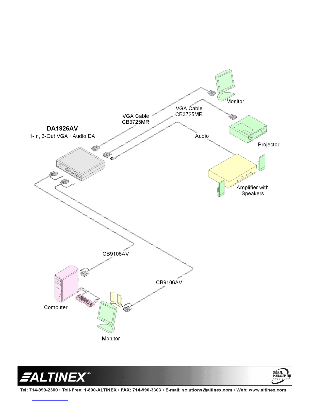
Altinex VA6803SX User manual

VA6803SX/DA1
VA6803SX/DA1VA6803SX/DA1
VA6803SX/DA1926AV
926AV926AV
926AV
C
CC
Compact
ompactompact
ompact A
A A
Analog
nalognalog
nalog I
I I
Interfaces
nterfacesnterfaces
nterfaces
User’s Guide
400-01 4-007
1
Welcome!
We greatly appreciate your purchase of the VA6803SX/DA1926AV Interface.
We are sure you will find it reliable and simple to use. Superior performance
for the right price, backed by solid technical and customer support is what
ALTINEX has to offer.
We are committed to providing our customers with
Signal Management Solutions
®
to the most demanding audiovisual
installations at very competitive pricing and we welcome you to join the
ranks of our many satisfied customers throughout the world.
1. Precautions and Safety Warnings
Please read this manual carefully before using your VA6803SX/DA1926AV.
Keep this manual handy for future reference. These safety instructions are to
ensure the long life of your unit and to prevent fire and shock hazards. Please
read them carefully and heed all warnings.
1.1 General
•Qualified ALTINEX service personnel or their authorized
representatives must perform all service.
1.2 Installation Precautions
•For best results, place the interface on a flat, leveled surface in a dry
area away from dust and moisture.
•To prevent fire or shock, do not expose this unit to water or moisture.
Do not place the interface in direct sunlight, near heaters, or
heat-radiating appliances, or near any liquid. Exposure to direct
sunlight, smoke, or steam can harm internal components.
•Handle the interface carefully. Dropping or jarring can damage the unit.
•Do not pull any cables that are attached to the interface.
•Do not place heavy objects on top of the interface.
•If the interface is not used for an extended period, disconnect the
adapter from the wall to avoid fire, shock, and loss of power.
1.3 Cleaning
•Unplug the VA6803SX/DA1926AV adapter before cleaning.
•Clean only the connector area with a dry cloth. Never use strong
detergents or solvents such as alcohol or thinner. Do not use a wet cloth
or water to clean the unit.
1.4 FCC Notice
•This device complies with Part 1 of the FCC Rules. Operation is
subject to the following two conditions: (1) This device may not cause
harmful interference, and (2) this device must accept any interference
received, including interference that may cause undesired operation.
•This equipment has been tested and found to comply with the limits for
a Class A digital device, pursuant to Part 1 of the FCC Rules. These
limits are designed to provide reasonable protection against harmful
interference when the equipment is operated in a commercial
environment. This equipment generates, uses, and can radiate radio
frequency energy and, if not installed and used in accordance with the
instructions found herein, may cause harmful interference to radio
communications. Operation of this equipment in a residential area is
likely to cause harmful interference in which case the user will be
required to correct the interference at his own expense.
•Any changes or modifications to the unit not expressly approved by
ALTINEX, Inc. could void the user’s authority to operate the
equipment.
2. Installation Procedures
Step 1. Connect the video and audio sources to the input ports on the interface. The inputs use standard audio and VGA-type cables.
Step 2. Connect the local video output of the VA6803SX/DA1926AV to the local monitor using standard VGA-type cable.
Step 3. Connect the local audio output of the VA6803SX/DA1926AV to the audio speakers at the local computer.
Step 4. Make the main video and audio output connections:
VA6803SX: Connect the main out BNCs to the projector/monitor. Typically, either a 4 or -BNC coaxial cable is used: 4 BNCs for
composite sync devices (RGBS) and BNCs for H&V sync devices (RGBHV).
DA1926AV: The DA1926AV has 2 main outputs. Connect the projectors/monitors to the 1 -pin HD main output connectors on the
DA1926AV using high-quality VGA-type cable. An unused output does NOT need to be terminated.
VA6803SX/DA1926AV: The main audio connects to the sound system amplifier using the terminal block connector; both interfaces can be wired for
balanced or unbalanced operation.
Step . Connect the external AC adapter provided with the unit to the interface and plug it in to AC power. The power indicator light on should turn on. The
LED will be red with power only and green if an input signal is present.
Step 6. Adjust the horizontal image position using the monitor or projector control. If further adjustments of the image are needed, use the knob located on the
left side of the VA6803SX.
Step 7. Adjust the equalization settings for the best image quality.
3. Limited Warranty/Return Policies
Please see the ALTINEX website at www.altinex.com for details on warranty and return policies.

VA6803SX/DA1926AV
VA6803SX/DA1926AVVA6803SX/DA1926AV
VA6803SX/DA1926AV
User’s Guide
400-01 4-007
2
4. Technical Specifications
Specifications are subject to change. See www.altinex.com for up-to-date information.
Features/Description VA6803SX/DA1926AV
Inputs
VA6803SX: VGA 15-pin HD F (1)
Audio 3.5 mm F (1)
DA1926AV: VGA 15-pin HD F (1)
Audio 3.5 mm F (1)
Outputs
VA6803SX: Main Video BNC F (5)
Main Audio 5-pin TB (1)
Local Video 15-pin HD F (1)
Local Audio 3.5 mm F (1)
DA1926AV: Main Video 15-pin HD F (2)
Main Audio 5-pin TB (1)
Local Video 15-pin HD F (1)
Local Audio 3.5 mm F (1)
Power
DC Power jack 2.5 mm F (1)
Compatibility
Signal Types RGB, RGsB, RGBS,
RGBHV, YPbPr
Video Signal Resolutions VGA through UXGA,
480p through 1080i
Accessories Included
Power Adapter +9VDC, 1.1 A
Hardware 5-pin terminal block
mating connector
Optional Accessories
Mounting Bracket MB1001
Patch Cable (18.0 in, 457 mm)
15-pin HD M to 5 BNC M MS6418VB
Table 1. VA6803SX/DA1926AV General
Mechanical VA6803SX/DA1926AV
Material/Color Aluminum/ALTINEX grey
VA6803SX/DA1926AV....Height 4.3 in (109 mm)
VA6803SX/DA1926AV....Width 5.2 in (132 mm)
DA1926AV ......................Depth 1.0 in (25 mm)
VA6803SX.......................Depth 1.1 in (28 mm)
Weight 0.7 lb (0.3 kg)
Shipping Weight (approx.) 1.5 lb (0.7 kg)
T°Operating 10°C-35°C
T°Maximum 50°C
Humidity 90%non-condensing
MTBF (calculations) 40,000 hrs (min.)
Table 2. VA6803SX/DA1926AV Mechanical
Electrical VA6803SX/DA1926AV
Video Input
Video Signal 1.2 Vp-p max
Video Impedance 75 ohms
Sync Input
Sync Level TTL (+/-)
Sync Impedance 10 kohms
Sync-on-Green -0.3 V
Audio Input Signal
Impedance 10 kohms
Level 0 dBu max
Video Output
Gain 0 dB +/- 0.5 dB
Impedance 75 ohms
Sync Output
Level TTL (+/-)
Impedance 22 ohms
Sync-on-Green -0.3 V
Audio Output
Impedance 50 ohms
Gain +0 dB balanced,
+6 dB unbalanced
Response 20 Hz to 20 kHz
+/- 0.5 dB
Power Consumption
+9V 400 mA
Total Power 3.6 W max.
Table 3. VA6803SX/DA1926AV Electrical

VA6803SX/DA1926AV
VA6803SX/DA1926AVVA6803SX/DA1926AV
VA6803SX/DA1926AV
User’s Guide
400-01 4-007
3
5. About Your VA6803SX/DA1926AV
The VA6803SX and DA1926AV interfaces are designed to resolve incompatibility issues that occur when displaying a computer image on a large screen data
projector or monitor. Both are high-resolution computer video interfaces with stereo audio and are designed to allow the connections of VGA, SVGA, XGA,
UXGA, MAC, SUN, SGI, and other analog computer video sources to scan-rate compatible monitors, projectors, and LCD displays.
These interfaces amplify video signals and convert various sync formats. They do not change the scan-rate or the resolution of the video signal. The computer
and projector must be scan-rate compatible with each other. The VA6803SX and DA1926AV can equalize the attenuation effects of long cable runs, up to 300 ft
(91 m), or more, depending upon the type of cable.
Each unit provides fully buffered main and local video outputs. The VA6803SX has one main output that is provided on BNC connectors, while the DA1926AV
has two main outputs that are provided on 1 -pin HD connectors. The local video outputs on both units are provided on a 1 -pin HD connector. On the
VA6803SX, if the input signal format is RGBS or RGBHV, the main output can be RGBHV, RGBS, or RGsB. If the input signal is RGsB, the output must be RGsB.
The VA6803SX and DA1926AV do not separate sync from green.
The VA6803SX and DA1926AV each accept stereo audio inputs and offer a balanced stereo output as well as a local stereo output. The input and local output use
3. mm jacks, while the main outputs are provided on -pin terminal blocks for stereo audio transmission to the main sound system. The main output can be
wired for balanced or unbalance audio.

VA6803SX/DA1926AV
VA6803SX/DA1926AVVA6803SX/DA1926AV
VA6803SX/DA1926AV
User’s Guide
400-01 4-007
4
6. Application Diagrams
Diagram 1: DA1926AV Typical Setup

VA6803SX/DA1926AV
VA6803SX/DA1926AVVA6803SX/DA1926AV
VA6803SX/DA1926AV
User’s Guide
400-01 4-007
5
Diagram 2: VA6803SX Typical Setup

VA6803SX/DA1926AV
VA6803SX/DA1926AVVA6803SX/DA1926AV
VA6803SX/DA1926AV
User’s Guide
400-01 4-007
6
Diagram 3: DA1926AV Internal View
DC POWER
2.5mm F
POWER
SUPPLY SIGNAL
DETECT
POWER
VIDEO IN
15-PIN HD F
EQ
H/W
MAIN VIDEO OUT 1
15-PIN HD F
STEREO AUDIO IN
3.5mm F
LOCAL AUDIO OUT
3.5mm F
MAIN AUDIO OUT
5-PIN TERMINAL
BLOCK
LOCAL VIDEO OUT
15-PIN HD F
MAIN VIDEO OUT 2
15-PIN HD F

VA6803SX/DA1926AV
VA6803SX/DA1926AVVA6803SX/DA1926AV
VA6803SX/DA1926AV
User’s Guide
400-01 4-007
7
Diagram 4: VA6803SX Internal View
STEREO AUDIO IN
3.5mm F
DC POWER
2.5mm F
VIDEO IN
15-PIN HD F
SYNC ON GRN
HOR INP
DEL H
HV ALIGN
HV PRES
MAIN AUDIO OUT
5-PIN TERMINAL
BLOCK
LOCAL AUDIO OUT
3.5mm F
LOCAL VIDEO OUT
15-PIN HD F
MAIN VIDEO OUT
5 BNC F (RGBHV)
EQ
H/V DELAY
CIRCUIT
H/W
POWER
SUPPLY SIGNAL
DETECT
POWER
H/W
HPos

VA6803SX/DA1926AV
VA6803SX/DA1926AVVA6803SX/DA1926AV
VA6803SX/DA1926AV
User’s Guide
400-01 4-007
8
Diagram 5: VA6803SX Internal Jumpers
Default Jumper Positions
SYNC-ON-GREEN (SOG)
J2
J5
J3
J4 J6
J1
DEFAULT=OFF,
HV PRES
DEFAULT=ON,
DEFAULT=OFF,
OPTIONAL
DEFAULT=OFF,
HV ALIGN
DEFAULT=ON,
HORIZ POS ADJUST
JUMPER ON ONE PIN ONLY
JUMPER BOTH PINS
JUMPER ON ONE PIN ONLY
JUMPER ON BOTH PINS OF J4
SOG also requires the HV PRES
jumper to be in the OFF position.
NOTE:

VA6803SX/DA1926AV
VA6803SX/DA1926AVVA6803SX/DA1926AV
VA6803SX/DA1926AV
User’s Guide
400-01 4-007
9
7. Operation
Once the horizontal position and equalization controls are set, the
VA6803SX/DA1926AV will operate successfully without user intervention.
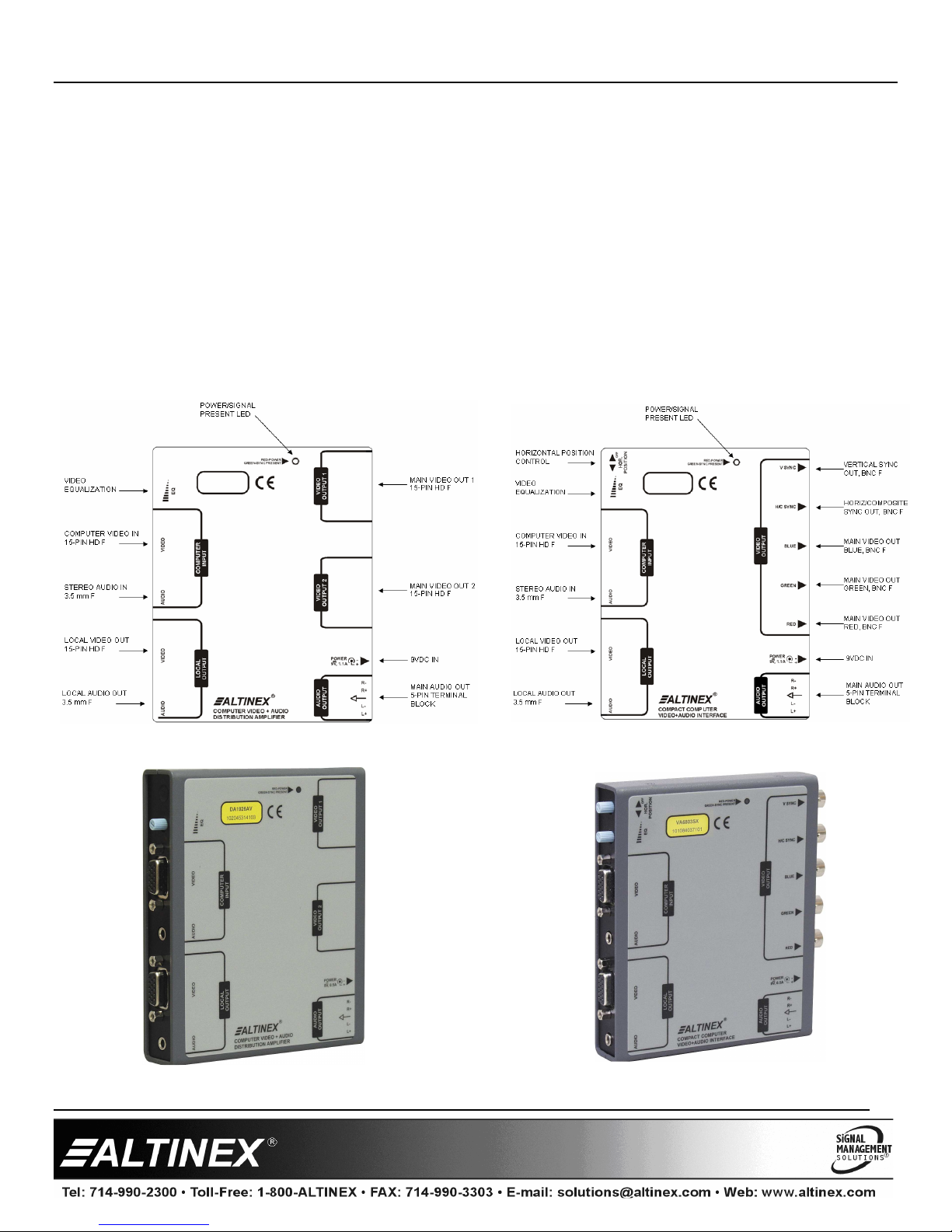
7.1 Horizontal Position (VA6803SX)
Most monitors and projectors are capable of horizontal position
adjustments. In some instances, like when using multiple computers, it is
helpful to adjust the horizontal position at the interface and often
simplifies the set up.
Turn the knob fully counterclockwise to turn off the horizontal position
control. Turn the knob clockwise to enable the horizontal position control
and to adjust the image as desired. It is recommended to first adjust the
horizontal position of the image using the monitor or projector Horizontal
Position control. If further adjustments are needed, use the VA6803SX.
7.2 Equalization
Equalization is a means of boosting the red, green, and blue signals at high
frequencies for cable runs over 100 ft (30 m), and up to 300 ft (91 m). The
equalization control should be set fully counterclockwise to minimum for
short cable runs. The longer the cable run, the more equalization is
required.
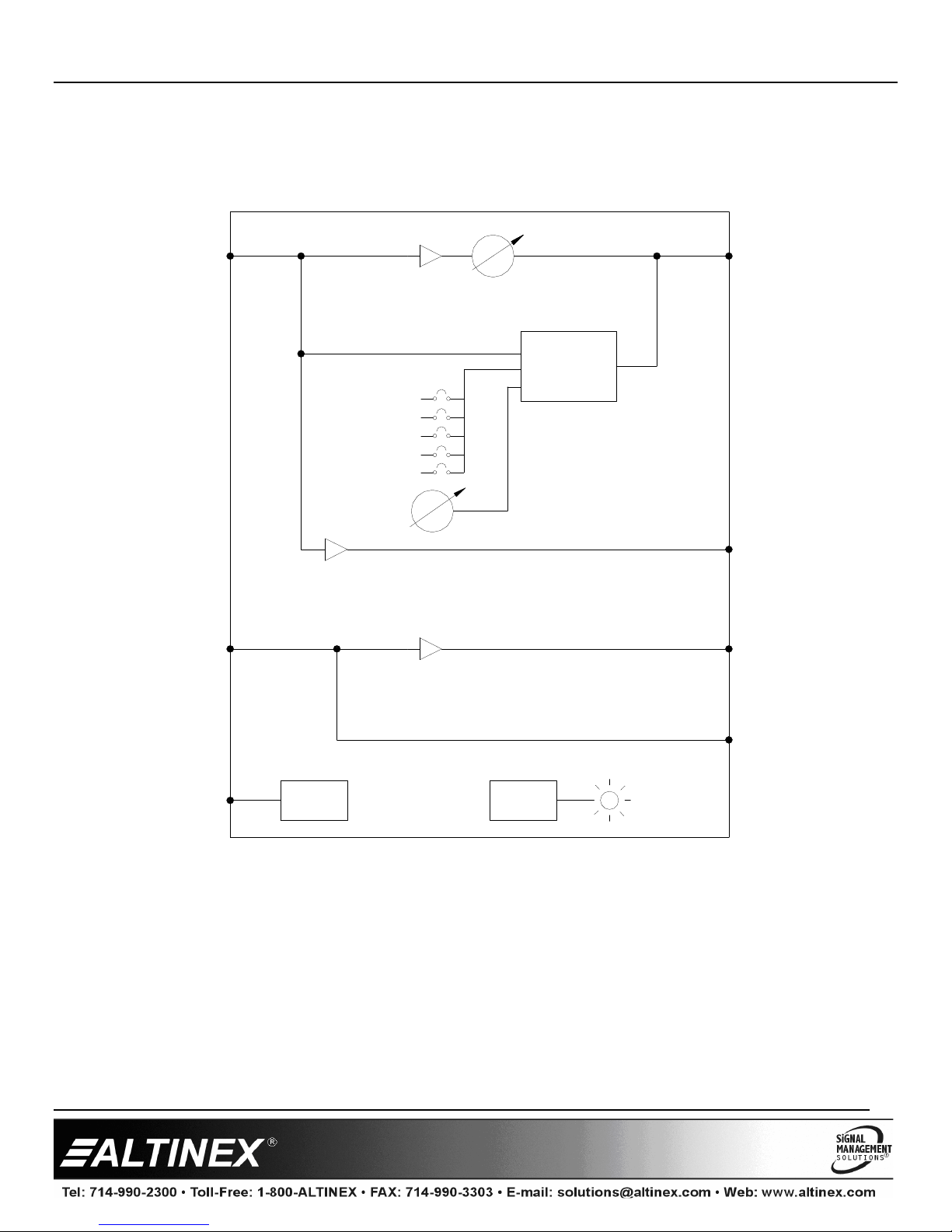
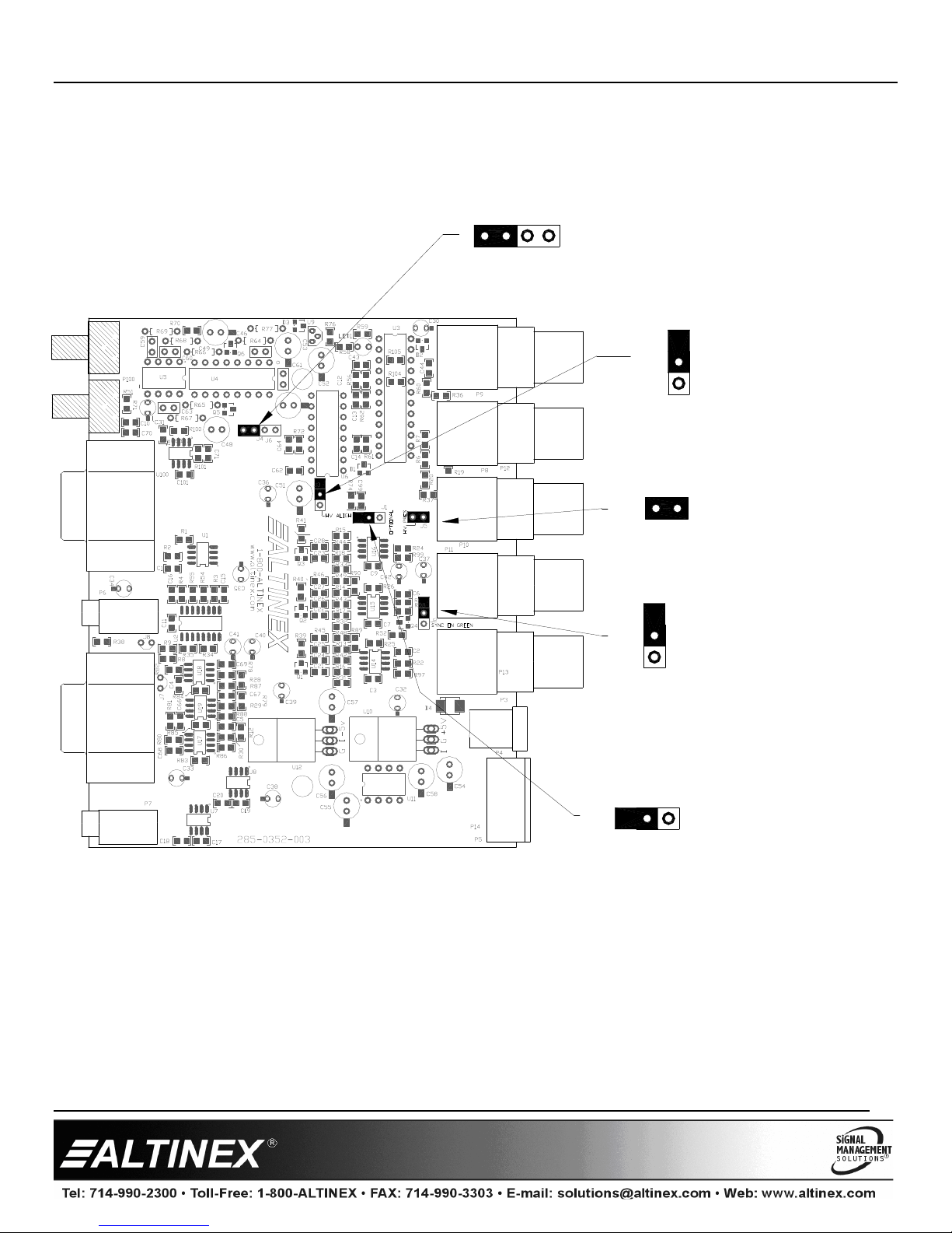
7.3 Sync-On-Green, SOG
Systems that use large matrix switchers are often designed to switch signals
in RGsB format in order to reduce costs. In these systems, the ability of the
VA6803SX/DA1926AV to pass sync-on-green can be very helpful.
The VA6803SX/DA1926AV cannot separate H&V sync from the green
signal if the input signal is RGsB. The VA6803SX can combine sync with
green video when the internal SOG jumper is set to the ON position and
the HV PRES jumper is in the OFF position regardless of whether the
input signal is RGBS or RGBHV.
8. Troubleshooting Guide
We have carefully tested and found no problems in the supplied
VA6803SX/DA1926AV; however, we would like to offer suggestions for
the following:
8.1 LED is Not Red
The LED should be ON and RED when power is applied and there is
no video signal present. If the LED is ON and GREEN, the unit is
receiving power and a SYNC signal.
Cause 1: No AC power.
Solution:
Verify the adapter is plugged into a working AC outlet and
that the outlet has power.
Cause 2: Adapter is not plugged into the device.
Solution:
Verify the DC power plug coming from the AC adapter is
plugged all the way into the VA6803SX/DA1926AV.
Cause 3: The device has a problem.
Solution:
If there is AC power to the adapter and the LED still does not
turn on, the VA6803SX/DA1926AV or the power adapter may
require service; call ALTINEX at (714) 990-2300.
8.2 LED is Not Green
Cause 1: There is no power.
Solution:
Disconnect the video input from the interface and verify the
LED is ON and RED indicating power is present. Reconnect
the computer's video output. If the LED is still not GREEN see
Cause 2.
Cause 2: There is no sync signal.
Solution:
Verify the computer output is operating correctly by
connecting it directly to the local monitor. If the display is
good, call ALTINEX at (714) 990-2300.
8.3 No Sound
Cause 1: The source has a problem.
Solution:
Check the source and make sure that there is a signal present
and all source connections are correct. If the source is working
and there is still no sound, see Cause 2.
Cause 2: The volume is too low.
Solution:
Increase the source level. If there is still no sound present, see
Cause 3.
Cause 3: Cable connections are incorrect.
Solution:
Make sure that cables are properly connected. Also, make sure
that the continuity and wiring are good. If there is still no
sound, see Cause 4.
Cause 4: The receiving device has a problem.
Solution:
Make sure the receiving device is powered and is turned on. If
there is still no sound, please call ALTINEX at (714) 990-2300.
8.4 No Remote Image
Cause 1: The source has a problem.
Solution:
Check the image on the local monitor and verify the quality is
good. If the local image is good, see Cause 2.
Cause 2: Cable connections are incorrect.
Solution:
Make sure that cables are connected properly. Also, make sure
that the continuity and wiring are good. If there is still no
image present, see Cause 3.
Cause 3: Video equalization required.
Solution:
Adjust the VIDEO EQUALIZATION on the interface. Cable
runs less than 100 ft (30 m) require little or no equalization and
should be set to minimum. Cable runs up to 300 ft (91 m) will
require near maximum equalization.
8.5 Remote Image Quality is Poor
Cause 1: The source has a problem.
Solution:
Check the image on the local monitor and verify the quality is
good. If the local image is good, see Cause 2.
Cause 2 Poor signal transmission.
Solution:
Check the cables for continuity and make sure that
connections are wired properly to verify that there is good
signal transmission. If the image is still not correct, call
ALTINEX at (714) 990-2300.
Cause 3: Video equalization required.
Solution:
Adjust the VIDEO EQUALIZATION on the interface. If the
image is still not correct, call ALTINEX at (714) 990-2300.

VA6803SX/DA1926AV
VA6803SX/DA1926AVVA6803SX/DA1926AV
VA6803SX/DA1926AV
User’s Guide
400-01 4-007
10
8.6 Miscellaneous Checks
VA6803SX/DA1926AV
•Make sure the amplitude level of the input signals are within spec:
RGB (red/green/blue): 0 to 1.2 Vp-p
(-0.3 for SOG)
HV (h-sync/v-sync): TTL (0 to .0 V)
•Use only the ALTINEX supplied power supply (AC Adapter) for
proper operation.
•If problems show up on the display after continuous usage at higher
voltage, higher temperature, higher humidity, or at other extreme
environmental conditions, please correct those extreme conditions.
•Disconnect the vertical sync connection when using devices that
require composite sync. Some monitors/projectors do not function or
behave erratically when both signals are present.
VA6803SX
•Adjust the horizontal position control of the display first and then use
the horizontal position control knob located on the interface only if
needed.
•If using RGsB format (sync-on-green), make sure that the
SYNC-ON-GREEN internal jumper inside of the unit is in the ON
position and that the HV PRES jumper is in the OFF position.
•Make sure that the HV PRES internal jumper is set in the OFF
position if using composite sync.
This manual suits for next models
1
Table of contents
Other Altinex Recording Equipment manuals

Altinex
Altinex MULTI-TASKER MT103-127 User manual

Altinex
Altinex YZ810-106 User manual

Altinex
Altinex System Analog Interface VA6834FC User manual

Altinex
Altinex DA203-101 User manual

Altinex
Altinex DA1926AV User manual

Altinex
Altinex VA6831FC User manual

Altinex
Altinex System Interface Audio & Equalization VA6822 User manual

Altinex
Altinex Wall Mount Interface with Twisted Pair (TP) Output... User manual

Altinex
Altinex VA6835FC User manual