Garnet SeeLeveL II 709 Series Troubleshooting guide

Page 1SeeLeveL II 709 Series Display Manual
HOLDING TANK MONITORS
CANADA
Garnet Instruments
286 Kaska Road
Sherwood Park, AB T8A 4G7
USA
Garnet US Inc.
5360 Old Granbury Road
Granbury, TX 76049
Through decades of experience and development the SeeLeveL tank
monitor series has established itself as the gold standard in level
measurement technology for the Recreational Vehicle industry.
The SeeLeveL II™ has a combination of features, accuracy, reliability, and
diagnostic capability that provide the best possible user experience.
Depending on the model, the SeeLeveL II monitors battery voltage, and
displays percentage of full readouts for FRESH, GREY, GALLEY, and BLACK
tank levels. In addition, the system can display the operating characteristics
of each of the tank sending units, giving it unsurpassed diagnostic
capability.
INTRODUCTION
709 Series Manual_v1.0 - 21-Oct-2022
DISPLAY INSTALLATION GUIDE
& USER MANUAL FOR 709 SERIES
709-2P |709 |709-P3 |709-P3W |709-HP3W
709-BTP3 | 709-RVC |709-RVC PM |709-RVC NLP
709-N2K NLP | 709-4 |709-4P |709-4LP
Document the following information for future reference. See page 4 for
more information.
Model Number: ___________________________________________________________
Serial Number: ____________________________________________________________
Date of purchase: _________________________________________________________

Page 2SeeLeveL II 709 Series Display Manual
SAFETY INFORMATION
WCAUTION: explains safety information that could cause damage to
the product, including data loss.
WWARNING: explains dangers that might result in personal injury or
death.
WNOTE: expands on information for any procedures.
Safety Symbols
Read these instructions carefully and look at the equipment to become
familiar with the device before trying to install, operate, service, or maintain
it. The following special messages may appear throughout this manual
or on the equipment to warn of potential hazards or to call attention to
information that claries or simplies a procedure. “Notes”, “Cautions”,
and “Warnings” have been used to bring special matters to the immediate
attention of the reader.
WWARNING: All power circuits must be fused. If a fuse is not provided with the system
then it is the installer’s responsibility to install a fuse with the maximum rating your model
requires. A relay may be required for models with a pump or heater switch. For
information about the requirements for your model please refer to the Specications
document located on our website.
For more detailed information please refer to the chapter entitled
TROUBLESHOOTING GUIDE”, section “How to avoid damaging the display or pump
switch due to excessive current”.
2022 Garnet Instruments. All rights reserved. No part of this publication may be reproduced,
Transmitted, transcribed, stored in a retrieval system or translated into any language in any
form by any means without the prior written consent of Garnet Instruments. Information in this
manual is subject to change without notice and does not represent a commitment on the part
of GARNET.
TABLE OF CONTENTS
INTRODUCTION........................................................................................................................1
SAFETY INFORMATION .......................................................................................................... 2
ABOUT THE SYSTEM............................................................................................................... 3
Series Model Features Table..................................................................................................... 4
Model and Serial Number Info................................................................................................ 4
INSTALLATION INFORMATION ............................................................................................ 4
Installation Documentation Downloads .............................................................................. 4
Tools and Equipment to Install Display................................................................................ 4
DISPLAY INSTALLATION......................................................................................................... 5
Display Panel Mounting Template ......................................................................................... 5
Connect Wiring to the Display ................................................................................................ 5
OPERATION GUIDE.................................................................................................................. 6
To Read a Water or Sewer Tank Level ................................................................................... 6
To Read the Battery Voltage ..................................................................................................... 6
To Read the LPG Tank Level (if equipped)........................................................................... 6
RV-C Bus Communication (if equipped).............................................................................. 7
NMEA 2000 Network (if equipped) ....................................................................................... 7
CONFIGURATION GUIDE ....................................................................................................... 8
Set the LED Brightness................................................................................................................ 8
Program the Number of Senders........................................................................................... 8
Calibrate the LPG Sender (if equipped) ............................................................................... 9
Set tank capacity (709-N2K NLP only).................................................................................. 9
Calibrate the Battery Voltage................................................................................................... 9
CONFIGURATION GUIDE (Bluetooth Model Only).........................................................10
Program Alarm Set Points for Each Tank...........................................................................10
Trip Polarity....................................................................................................................................10
Inclusion in the Common Alarm Output ...........................................................................10
Failure Polarity (if equipped with LPG) ...............................................................................10
Program the Display as Primary or Secondary................................................................11
Check the Primary/Secondary Mode ..................................................................................11
Enable/Disable the LPG Sender (if equipped with LPG) ..............................................11
Check Hardware/Software Revision ....................................................................................11
TROUBLESHOOTING GUIDE.................................................................................................12
Error Codes....................................................................................................................................12
Sender Diagnostics ....................................................................................................................12
RV-C Diagnostics (if equipped).............................................................................................13
Wiring Diagnostics .....................................................................................................................14
Troubleshooting & Installation Tips ....................................................................................16
WARRANTY & SERVICE INFORMATION............................................................................18
Select from contents list below to go to that page.
Pump and Heater Switch Safety Precaution
Changes or modications not expressly approved by the party responsible
for compliance could void the user’s authority to operate the equipment.

Page 3SeeLeveL II 709 Series Display Manual
ABOUT THE SYSTEM
The Senders
Each sender panel is a exible self-adhesive printed circuit board which is
adhered to the side of the holding tank. The sender panel can be cut to length
to match the height of the tank, and it auto calibrates itself so that it can read
from Empty to Full regardless of the height of the tank.
In addition to the level, the sender also transmits diagnostic information about
its operation. This information can be used to determine if there is buildup of
sludge on the inside of the tank, or to determine if the sender is damaged or
delaminating from the side of the tank. If sludge buildup in the tank becomes
extreme the gauge will cease to operate properly, so by monitoring the signal
power the tank can be cleaned before the buildup gets excessive.
Multiple senders are available with the ability to double stack the senders to
provide accurate level measurement for tank heights ranging from 4” to 25”.
(See Sender Installation guide for available sender options-link on page 4)
The Display
The display receives the information from sender panels via a single 2 conductor
wire and shows the level information in percent of full on a 3-digit LED display,
from 0% to 100%. When the button for a particular tank is pressed, the display
shows the level for that tank.
Battery Voltage
The system also shows the RV battery voltage by measuring the voltage which
powers the display. The voltage is shown with a resolution of 0.1 volt.
Diagnostics
If a sender is operating properly and connected to the display with good wiring,
then the display will show the level normally. If the wiring is disconnected,
shorted, cut, or if the sender panel is defective, then the display will indicate
an error code. The various error codes are shown in the section entitled
“TROUBLESHOOTING GUIDE”.
With these diagnostic features and the digital nature of the tank level sensing
technology, it is almost impossible for the system to indicate an incorrect water
level, and in the very unlikely event it does occur, servicing is greatly aided with
the diagnostic information.
LPG (if equipped)
The display can use an existing LPG electrical sender to show the LPG level. It
can be automatically calibrated to any sender and shows the level information
in percent of full on a 3-digit LED display, from 0% to 100%.
Bluetooth® (if equipped)
The display has Bluetooth® wireless technology, which allows you to check
your tank levels, battery voltage, and LPG tank levels on any compatible
smartphone or tablet device with a free downloadable app available on both
iTunes and Google Play. This model include one alarm output which can be
used to signal a high or low water or sewer level as required.
(See separate manual for app installation and operation-link on page 4)
RV-C (if equipped)
Models equipped with RV-C are compatible with RV’s that have an RV-C
network system. These models include one alarm output which can be used to
signal a high or low water or sewer level as required.
Dierent Display Types (If equipped)
Displays with RV-C, Bluetooth, or Alarms operate dierently from displays
without these features. In order to keep the tank level and alarm information
current, these displays regularly scan the senders every 10 to 15 seconds. When
a tank button is pressed, the information displayed is recalled from the most
recent scan. A tank on hold is scanned more frequently. Systems with two
displays are congured so that the primary display initiates the scanning and
the secondary display passively listens to the sender information, this way both
displays stay updated without interfering with each other.
Alarm Output (If equipped)
The single common alarm output can be programmed to indicate a high or low
sewage level, a high or low water level, or a high or low LPG level. More than
one alarm can be assigned to the alarm output. This output can be connected
to an indicator light and used to show a high sewer level and/or a low water
level, alerting the user that attention is required. Another example is the alarm
could be used on the black tank to prevent toilet use when the tank is full.
NMEA 2000 Network (If equipped)
Model 709-N2K NLP is NMEA 2000 Network compatible, the tank levels and
capacity are available on the NMEA Bus.

Page 4SeeLeveL II 709 Series Display Manual
Tools and Equipment to Install Display
□screwdriver or power driver
□wire cutters/stripper
□wire crimper
□electrical tape
□butt connectors
□saw to cut a hole for display (if required)
Optional items available to purchase if required. Go to our website for
more information:
□Filler Panel to t previous display hole that is too large.
□Gasket to prevent the display monitor from shorting if mounting to a
metal surface.
INSTALLATION INFORMATION
The installation for the complete system consists of mounting the display
inside the RV, programming, cutting, and mounting the senders to the
sides of the tanks, connecting the wiring, and programming the display.
This manual provides information for all 709 series models. It is important
to read carefully for specic instructions about your model. See Series
Model Feature table to nd out the features on each model.
Installation Documentation Downloads
Other documentation will be required to complete installation for your
specic model. Get them from our website Resource Library either by
selecting the link below or scan the QR code and search for your model.
garnetinstruments.com/holding-tanks-resource-library/
• Sender Installation Manual
• Wiring diagrams
• 709-BTP3 Bluetooth App manual (if equipped)
• Specications - download link at RVgauge.com
Model and Serial Number Info
Before installing your system, look for the model and serial number on the
back of the display, as shown below. Write these numbers on the inside
cover of this handbook for future reference.
No.
Tanks
Pump
Switch
7.5 amp
Pump
Switch
10 amp
Heater
Switch
10 amp LPG BATT RV-C Bluetooth
709-2P 2 . .
709 3 . .
709-P3 3 . .
709-P3W 3 . . .
709-HP3W 3 . . . .
709-BTP3 3 . . . .
709-RVC 3 . . .
709-RVC PM 3 . . . .
709-RVC NLP 3 . . .
709-N2K NLP .
709-4 4 .
709-4P 4 . .
709-4LP 4 . . .
Series Model Features Table
WCAUTION: If a pump or heater requires more amperage than the
switch allows, a relay is required.
RESOURCE
LIBRARY
Page 5SeeLeveL II 709 Series Display Manual
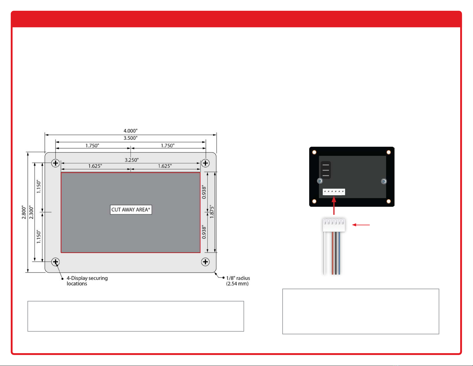
Connect Wiring to the Display
It is easier to connect the wiring to the display connector rst, and
then plug the connector into the display panel. Refer to the wiring
diagram for your model from our Resource Library using the link
or QR code on page 4.
The senders need to be grounded to a single ground wire from the
display. Make sure that the system ground is connected to the
breaker panel ground.
WWARNING: All power circuits must be fused. If a fuse is not
provided with the system then it is the installer’s responsibility to install
a fuse with the maximum rating your model requires.
A relay may be required for models with a pump or heater switch.
For information about the requirements for your model please
refer to the specications page and wiring diagram.
DISPLAY INSTALLATION
The installation consists of mounting the display inside the RV, programming, cutting and fastening the senders to the sides of the holding tanks, connecting the
wiring, and programming the display. When wiring DO NOT use spade connectors to join wires, only use crimp-on butt connectors or solder the wires together.
WCAUTION: If mounting the display in a metal panel or wall there is a risk the display can short
circuit causing permanent damage. Non-conductive mounting spacers are available to purchase to
help prevent damaging the display. Contact Garnet or go to our website for further details. More
installation tips are available in the “Troubleshooting and Installation Tips” section.
Display
connector
Display Panel Mounting Template
Mount the display by cutting a hole in the wall with the given dimensions plus
four screw holes. The thickness of the RV wall needs to be thick enough to retain
the screws. The panel will be mounted onto the wall using the four included
#4 screws, or dierent screws as required. The cutout diagram below is actual
size and can be used as a template. The depth of each model varies 1” - 1 3/8”
(25 - 35 mm), model dependent.
Page 6SeeLeveL II 709 Series Display Manual
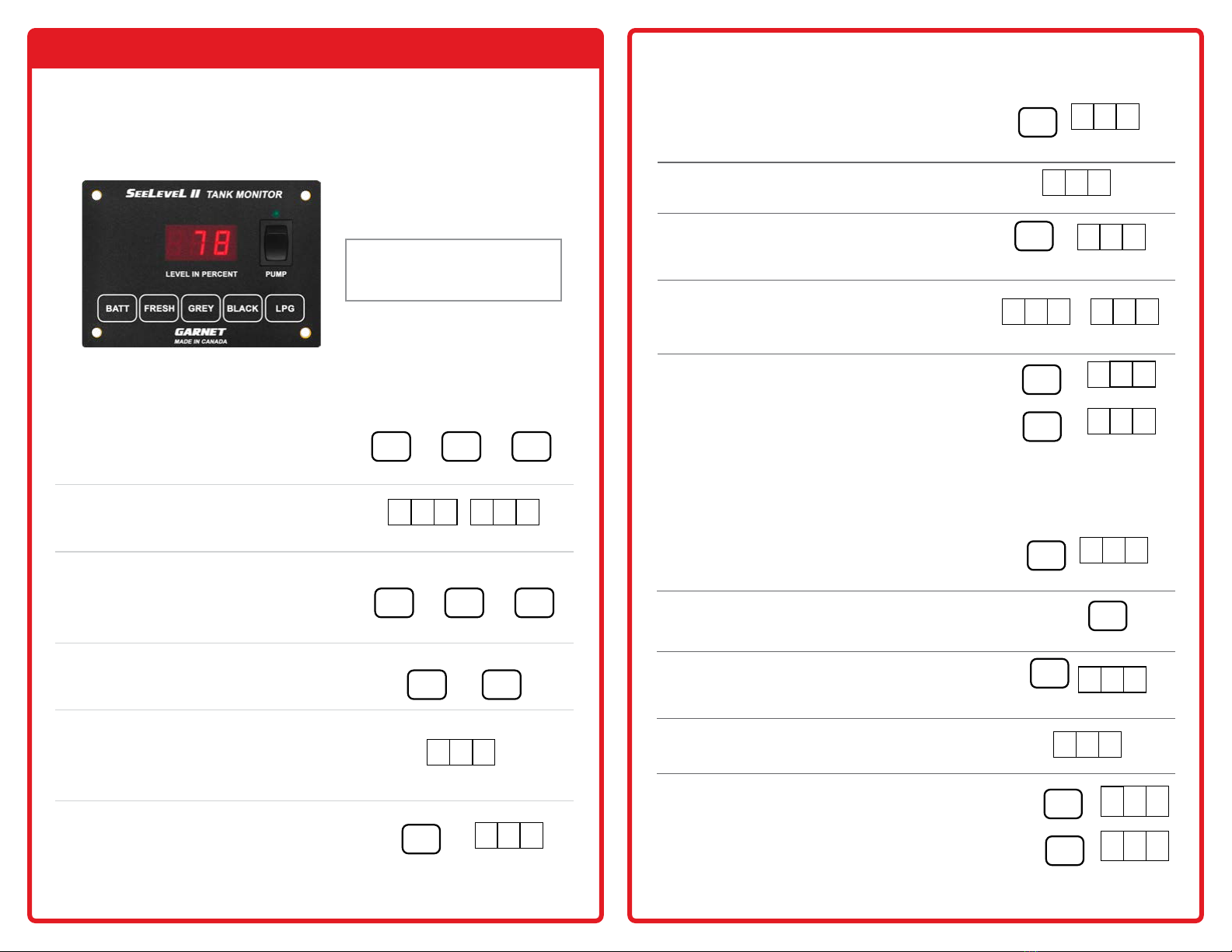
OPERATION GUIDE
The display is the only system component that is accessed by the user. All
user input to the display is done using the buttons along the bottom of the
display. Operation of the display is as follows:
1. Press and release button for the
corresponding tank.
2. LED display shows the level in percent.
Display shuts o after about 5 seconds.
3. To read another tank level, battery voltage
or LPG level press that corresponding
button before the 5 seconds is up. The 5
second time-out is restarted every time a
button is pressed.
4. To continuously display reading, press and
release the desired button twice.
5. Continuous display mode is indicated by a
decimal point on the right hand side. The
level is updated once per second. User
can watch the level change while the tank
is being lled or drained.
6. Continuous display mode shuts o after
5 minutes. To end the hold mode sooner,
press any tank button and display will shut
o.
or
or or
FRESH GREY BLACK
BATT LPG
FRESH +FRESH
To Read a Water or Sewer Tank Level
or
FRESH
GREY
BLACK
LEVEL IN PERCENT
7 8
LEVEL IN PERCENT
1. Press and release the BATT button to display
the battery voltage. LED display shows the
battery level in volts.
2. The display shuts o after about 5 seconds.
3. Hold the BATT button and the display will
continuously re-check voltage and show
updated value.
4. The reading may icker back and forth
between two values, for example, 12.6 and
12.7 volts. This is normal behavior for a
digital voltage display.
5. To read a tank level press the corresponding
button before the 5 seconds is up. The 5
second time-out is restarted every time a
button is pressed.
To Read the Battery Voltage
Hold
or
+
BATT
BATT
GREY
LPG
LEVEL IN PERCENT
2 3
LEVEL IN PERCENT
5 6
LEVEL IN PERCENT
12. 6
LEVEL IN PERCENT
12. 7
LEVEL IN PERCENT
12. 6
LEVEL IN PERCENT
12. 0
LEVEL IN PERCENT
=
+FRESH
LEVEL IN PERCENT
78.
LEVEL IN PERCENT
1. Press and release the LPG button. Display
shuts o after about 5 seconds.
2. Press and release the LPG again, to display
a new reading. The 5 second timer will be
restarted.
3. Hold the LPG button and reading will remain
displayed.
4. The display will shut o 5 seconds after the
button is released.
5. To read another tank level or battery voltage
press that corresponding button before the 5
second time is up for the LPG. The 5 second
time-out is restarted every time a button is
pressed.
To Read the LPG Tank Level (if equipped)
+
or
+
Hold
LPG
LPG
LPG
GREY
BAT T
LEVEL IN PERCENT
7 8
LEVEL IN PERCENT
12. 0
LEVEL IN PERCENT
5 6
LEVEL IN PERCENT
5 6
LEVEL IN PERCENT
WNOTE: The model shown is a
709-P3W. Some models may have
dierent button and switch options.

Page 7SeeLeveL II 709 Series Display Manual
RV-C is a communications protocol based on CAN that is used for control,
coordination, and diagnostics. CAN bus interface allows continuous
communication with RV-C compatible systems.
The senders use a default source address of 72 and SPN-ISB instances are
0 for fresh, 1 for black, 2 for grey and 18 for galley (depending how the
display is equipped). The LPG sensor uses a default source address of 73
and a SPN-ISB instance of 3.
1. By disabling the LPG or changing the FRESH/GREY/BLACK to zero
senders, you are disabling that sender’s updates over the RV-C bus as
well.
2. The RV-C has a 4-pin connector as shown in the yellow box in the
image below. The connector pins conform to the RV-C standard.
3. All RV-C displays will have a wired connection for the RV-C Bus in
addition to the 4-pin connector as shown in the green box in the image
below. Refer to the wiring diagrams for each specic model for pin out
details.
RV-C Bus Communication (if equipped)
WNOTE: Anyone that intends on connecting to the RV-C bus should have a knowledge of
the RV-C specication. For more information on RV-C protocol go to: www.rv-c.com
NMEA 2000 is a marine communications protocol that is used for control,
coordination, and diagnostics. The 709-N2K is NMEA 2000 network
compatible, the tank levels and capacity are available on the NMEA bus for
the fresh, grey, and black tanks.
The 709-N2K reports as NMEA device class 75 (sensor communication
interface) with an NMEA function code of 150 (uid level). Garnet
Instrument’s manufacturer code is 873, and the 709-N2K product code
is 15197. The 709-N2K adheres to NMEA database version 2.200. By
changing the FRESH/GREY/BLACK to zero senders, you are disabling that
sender’s updates over the NMEA bus as well.
The display has a 4-pin connector as shown in the yellow box in the image
below. Refer to the wiring diagram for pin out details.
The pin closest to the tab on the connector is pin 1.
You can purchase the connector required to connect to our display on the
Digi-Key website. Digikey part #3M155844-ND.
NMEA 2000 Network (if equipped)
W NOTE: Anyone that intends to connect to the NMEA 2000 bus should have
a knowledge of the NMEA 2000 specication. For more information on NMEA
2000 protocol go to: www.nmea.org.
NMEA Connector Pinout
Pin Signal Description
1 +Voltage
2 CAN-Hi
3 CAN-Lo
4 -Voltage
RV-C Connector
Pin Signal Description
1 Open
2 CAN-Hi
3 CAN-Lo
4 Ground
Page 8SeeLeveL II 709 Series Display Manual
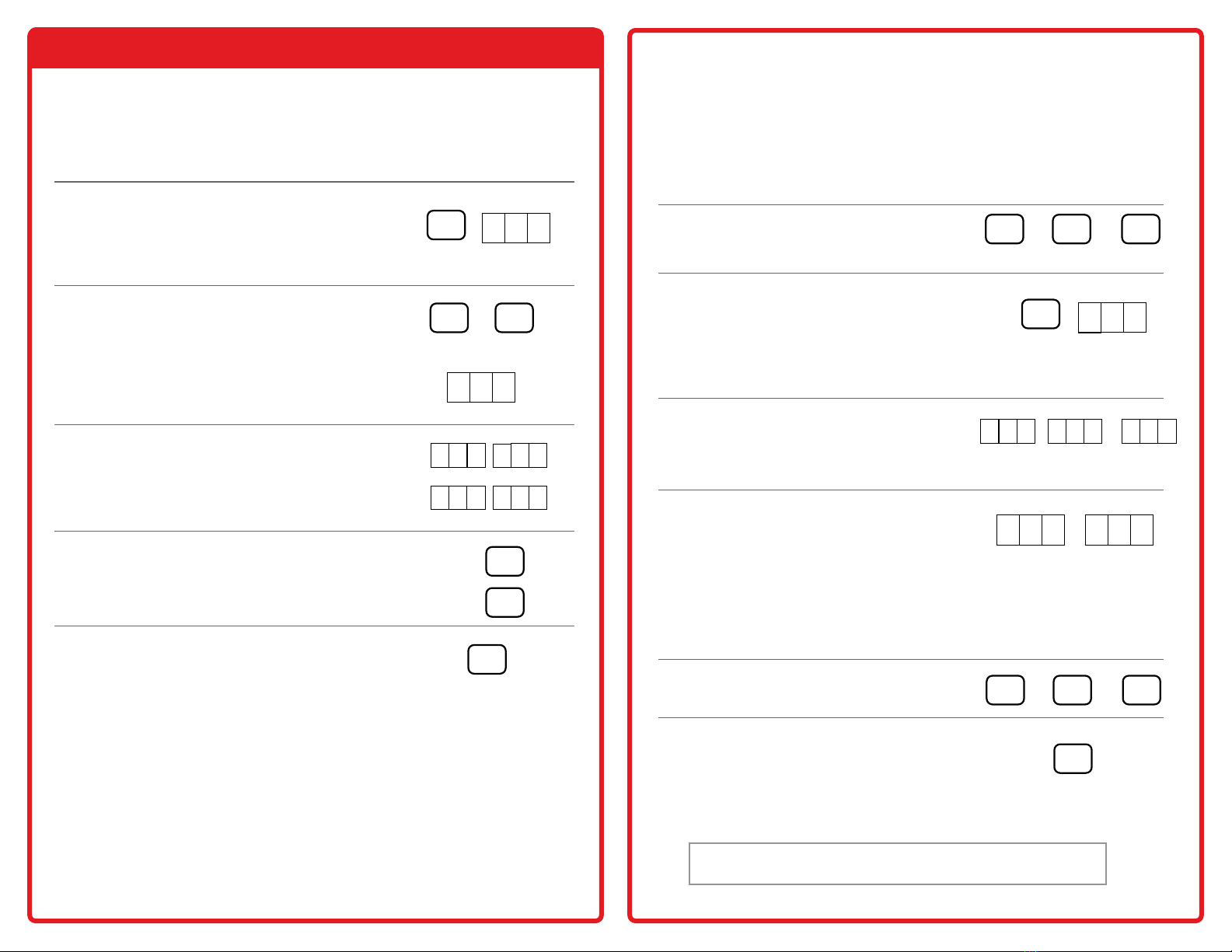
CONFIGURATION GUIDE
Set the LED Brightness
The LED brightness can be adjusted to suit the user and the operational
circumstances. If it is to be used in the service bay area where sunlight can reach
it, the LED brightness should be high.
1. To program the LED brightness, the
display needs to enter the brightness
programming mode. To do this, press and
hold down the BATT button, the display
will show the battery voltage.
2. Continue to hold down the BATT button,
press and hold the GREY button (use
the BLACK button for 709-2P). Continue
to hold down both buttons for about
5 seconds until the display shows
bri indicating brightness programming
mode. Then release both buttons.
3. The current brightness level is displayed.
b-1 is the minimum brightness and b-4 is
the maximum brightness.
4. Press the GREY tank button (use the
BLACK button for 709-2P) to increase
brightness, or the FRESH tank button to
decrease brightness.
5. When the display shows the correct
brightness, press the BATT button to exit
the programming mode.
Hold
+
Hold
BATT
GREY
LEVEL IN PERCENT
b- 2
LEVEL IN PERCENT
b- 3
LEVEL IN PERCENT
b- 4
LEVEL IN PERCENT
b- 1
FRESH
GREY
BATT
LEVEL IN PERCENT
12. 6
LEVEL IN PERCENT
br i
Hold
BATT
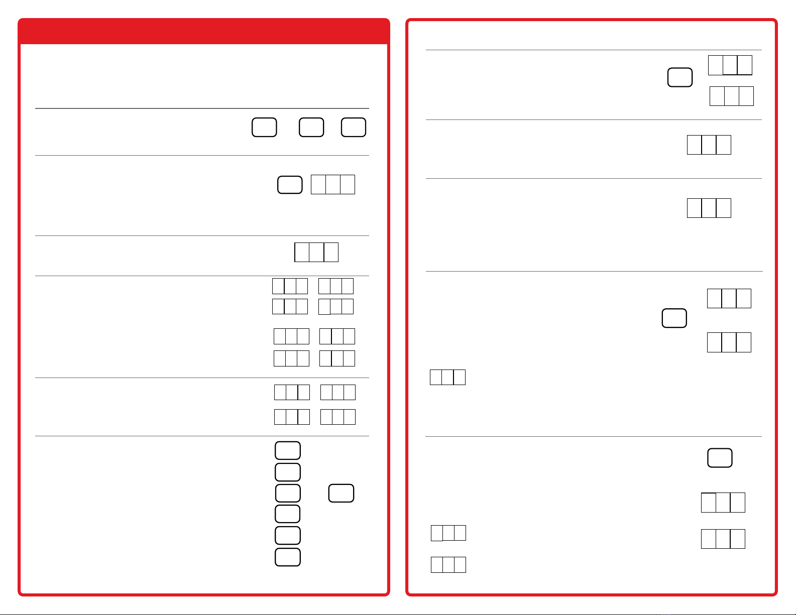
Program the Number of Senders
To program the number of senders for each tank, the display needs to enter
the sender programming mode. By default each tank is set for single sender
application. This should only be done at the time of installation; there is no
reason to change the number of senders afterward. Make sure that the number
of senders programmed into the display matches with the number of senders
connected; otherwise the display will show an error.
1. Press and hold down the button for the tank
to be programmed, the display may show a
level or an error message for that tank.
2. Continue to hold down the button for the
tank, and hold down the BATT button. The
display will show dIA (diagnostics). Continue
to hold down both buttons until the display
enters the programming mode, this should
take about 5 seconds (RV-C, BTP3, and N2K
models take about 10 seconds).
3. When the programming mode is entered, the
display will show FrS if entering the number
of senders for the fresh tank, GrS if entering
the Grey tank, or bLS if entering the black
tank. When this occurs release both buttons.
4. The display will show 1SE (one sender) or
2SE (two senders). This is what is currently
programmed into the display. These are the
only two options; the display will not work
with more than two senders per tank.
Note: For classic versions, 1 or 2 senders
are the only options, but for RV-C and BTP3
the options are 0, 1, or 2 senders. 0 senders
removes that tank from the RVC or bluetooth
data.
5. To change the number of senders, press the
tank button, each time the button is pressed
the display will toggle between 1SE and 2SE.
6. When the display shows the correct number
of senders, press the BATT button to save
any changes to exit the programming
mode. Each tank will need to be calibrated
individually using this procedure.
Hold
+
1 Sender 2 Senders
or or
Hold Hold
FRESH GREY
BATT
BATT
LEVEL IN PERCENT
15 E
LEVEL IN PERCENT
25 E
Hold
BLACK
LEVEL IN PERCENT
D1 A
or or
FRESH GREY BLACK
WCAUTION: For displays that have a GALLEY button the GREY and
GALLEY tanks can only have one sender per tank and cannot be stacked.
Fresh Grey Black
LEVEL IN PERCENT
fr S
LEVEL IN PERCENT
bL S
LEVEL IN PERCENT
Gr S

Page 9SeeLeveL II 709 Series Display Manual
The LPG tank must be full when the sender is calibrated, otherwise
the calibration will be invalid. Fill the LPG tank by using an alternate
measurement method, such as weight, a spit valve, or a mechanical gauge
on the tank.
1. To calibrate, press and hold the LPG
button, the display will show some LPG
level.
2. Continue to hold down the LPG button,
press and hold down the BATT button.
Continue to hold down both buttons for
about 5 seconds until the display shows
LPG.
3. When LPG displays release both buttons,
the display will show CAL for a second
and then shut o, completing the
calibration procedure.
4. The LPG can be re-calibrated as many times as desired, although recalibration
should not be needed unless the LPG tank sender or the display has been
replaced.
Calibrate the LPG Sender (if equipped)
Hold
Hold
+
BATT
LPG
LEVEL IN PERCENT
5 6
LEVEL IN PERCENT
LP G
LEVEL IN PERCENT
CA L
Calibrate the Battery Voltage
In order to properly recalibrate the battery voltage, supply 13.0 Vdc to the display.
The display will recalibrate to 13.0 volts, supplying voltage greater or less than
13.0 volts will cause the displayed voltage to be inaccurate.
1. Remove power from the display.
2. Press and hold the BATT button.
Continue to hold the BATT button for the
remainder of the steps.
3. Apply 13.0 Vdc to the display.
4. Continue to hold the BATT button until
the voltage appears. When this occurs
release the BATT button.
Hold
BATT
LEVEL IN PERCENT
13. 0
Hold
BATT
Hold
BATT
LEVEL IN PERCENT
13. 0
WWARNING: This should not normally ever need to be done, it is a factory calibration. In
the unlikely event that the battery voltage is very inaccurate, this procedure can be tried to
correct the error.
1. Press and hold down the tank button to
be programmed, then press and hold the
BATT button. After 15 seconds, the tank
capacity edit mode is displayed.
2. The display will show either FcA if
entering the tank capacity for the fresh
tank, GcA for the Grey tank, or bcA for the
black tank.
3. The unit will display the tank capacity in
US gallons. Press the GREY tank button
to increase, or the FRESH tank button to
decrease.
4. When the display shows the correct tank
capacity, press the BATT button to save
changes and exit programming mode.
Set tank capacity (709-N2K NLP only)
or or
Hold Hold
FRESH GREY
Hold
BLACK
Fresh Grey Black
FRESH
GREY
BATT
LEVEL IN PERCENT
fc A
LEVEL IN PERCENT
bc A
LEVEL IN PERCENT
Gc A
Hold
+BATT
Page 10SeeLeveL II 709 Series Display Manual
Trip Polarity
Inclusion in the Common Alarm Output
Failure Polarity (if equipped with LPG)
1. While the BLACK button is held down, the display
shows “Hi” on the left for a high level alarm or
“Lo” for a low level alarm.
2. After the button is released, the left digit shows
“H” for a high level alarm which means the alarm
turns on (closes) when the uid level is equal to
or higher than the set point, and the alarm is o
(open) when the uid level is below the set point.
3. An “L” shows a low level alarm which means the
alarm turns on (closes) when the uid level is
below the set point, and the alarm is o (open)
when the uid level is equal to or above the set
point.
While the BLACK button is held down, the display
shows an “i” on the right if the alarm is included and
an “n” if not included. After the button is released
the decimal on the right indicates that the alarm is
included in the common alarm output. If any of the
included alarms are on, then the common alarm is
on. All of the included alarms must be o for the
common alarm to be o.
While the LPG button is held down the display shows
“FtF” for fail to full, or “FtE” for fail to empty. After
the button is released, the left decimal on shows fail to
full which means that if the sender fails the alarm acts
as though the tank is full. The left decimal o shows
fail to empty which means that if the sender fails the
alarm acts as though the tank is empty. or
Hold
BLACK
Hold
Hold
BLACK LEVEL IN PERCENT
Hi
LEVEL IN PERCENT
Lo
LEVEL IN PERCENT
Ft F
LEVEL IN PERCENT
FT E
LEVEL IN PERCENT
H
LEVEL IN PERCENT
L
LEVEL IN PERCENT
i
Program Alarm Set Points for Each Tank
To program the alarm point for each tank, the display needs to enter the alarm
programming mode.
1. To enter the alarm programming mode, press
and hold down the button for the tank to be
programmed, the display may show a level or
an error message for that tank.
2. While continuing to hold down the button
for the tank, press and hold down the BATT
button. The display will immediately show
”dIA” (diagnostics), continue to hold down
both buttons until the display enters the alarm
test menu, this should take about 5 seconds.
The LPG tank does not show “dIA”.
3. When the alarm test menu is entered, the
display will show “ALr” for about 5 seconds.
Release the buttons.
4. Depending on which tank is selected and
the status of the alarm, the display will show
a simulated low uid level below the alarm
set point (FLo, GLo, bLo, LLo) or a high
level above the alarm point (FHi, GHi, bHi,
LHi). The alarm test menu allows the alarms
to be manually activated to test. The same
tank button toggles the simulated uid level
between low and high.
5. To set the alarm point, press and hold the
same tank button, after about 3 more seconds,
the display will show “FAS” (Fresh Alarm Set),
“GAS”, or “bAS”, “LAS”, depending on which
tank is selected. Release the button.
or or
Hold Hold Hold
Hold
+
Q
E
8
FRESH GREY BLACK
BAT T
LEVEL IN PERCENT
GL o
LEVEL IN PERCENT
bL o
LEVEL IN PERCENT
lL o
LEVEL IN PERCENT
FL o
LEVEL IN PERCENT
GH i
LEVEL IN PERCENT
bH i
LEVEL IN PERCENT
lH i
LEVEL IN PERCENT
FH i
LEVEL IN PERCENT
GA 5
LEVEL IN PERCENT
bA 5
LEVEL IN PERCENT
lA 5
LEVEL IN PERCENT
FA 5
BATT
LPG
FRESH
GREY
BLACK
GREY
or
To set the alarm point, the GREY button increases the
value.
The FRESH button decreases the value.
If the FRESH or GREY buttons are held down, after 1
second the numbers will change quickly. The alarm point
can be from 0% to 99%.
The BLACK button cycles through the trip polarity and
the inclusion in the common alarm output.
The LPG button toggles the failure polarity.
The BATT button saves and returns to the previous menu.
6.
FRESH
LEVEL IN PERCENT
di A
LEVEL IN PERCENT
AL r
CONFIGURATION GUIDE (BLUETOOTH MODEL ONLY)
LEVEL IN PERCENT
H90.
LPG
LEVEL IN PERCENT
L2 0
LEVEL IN PERCENT
H90.
.
LEVEL IN PERCENT
n
(Low level alarm at 20%, not included in
the common alarm and fail to empty.)
(Hi level alarm at 90%, included in
the common alarm and fail to full.)
(Alarm included in common output)

Page 11SeeLeveL II 709 Series Display Manual
Program the Display as Primary or Secondary
Check the Primary/Secondary Mode
This setting should normally only need to be done when installing the
gauge. An optional second display can be added to the system. This
allows for a display in the service bay and one inside the coach. To avoid
reading errors when using dual displays, one display needs to be set to
secondary mode. A display in secondary mode monitors the primary
displays sender requests and will only scan the tank levels at a much
slower rate if the primary display is disconnected. The alarms are inactive
on the secondary display. All RVC displays are primary by default.
To program a display to be either primary or secondary display:
1. With power removed, press and hold the
BATT and FRESH buttons and then power
the display.
2. The display will show “Scn” for 5 seconds,
then change to “SEC” or “Pri” depending on
current programming.
3. The FRESH button sets the mode to PRIMARY
the GREY button to SECONDARY
the BATT button saves and exits.
+
1. Press and hold down the BATT button, the
display will show the battery voltage.
2. While continuing to hold down the BATT
button, press and hold down the BLACK
button.
3. Continue to hold down both buttons for
about 5 seconds until the display shows
“Pri” for primary mode or “SEC” for
secondary mode. When viewing is complete,
release both buttons to return to normal
operation.
or
LEVEL IN PERCENT
Sc n
LEVEL IN PERCENT
SE C
LEVEL IN PERCENT
Pr i
LEVEL IN PERCENT
SE C
LEVEL IN PERCENT
Pr i
LEVEL IN PERCENT
12. 0
Check Hardware/Software Revision
Hardware and software updates may be periodically released to add
features. To check the hardware and software version of the display, use
the following procedure.
1. Press and hold down the BATT button, the
display will show the battery voltage.
2. While continuing to hold down the BATT
button, press and hold down the FRESH
button.
3. Continue to hold down both buttons for
about 5 seconds until the display shows a
number such as “4.10”, the rst number is the
hardware version and the last two numbers
are the software version. When viewing is
complete, release both buttons to return to
normal operation.
+
LEVEL IN PERCENT
12. 0
LEVEL IN PERCENT
4. 1 0
Enable/Disable the LPG Sender (if equipped with LPG)
The LPG sender can only be disabled from the primary display of
RVC and Bluetooth models. If these steps are used on the secondary
display, no change will result.
1. Press and hold down the LPG button.
2. While continuing to hold down the LPG
button, press and hold down the BATT
button. Continue to hold down both buttons
for about 10 seconds until the display shows
“AbL”.
3. When this occurs release both buttons, the
display will show “En” for enabled or “diS”
for disabled.
4. Press the LPG button to switch between
enabled and disabled.
5. Press the BATT button to save and exit the
menu.
Hold
or
Hold
+LPG
BATT
BATT
+
LEVEL IN PERCENT
E n
LEVEL IN PERCENT
di 5
LEVEL IN PERCENT
Ab L
LEVEL IN PERCENT
LP G
BAT T FRESH
FRESH GREY
BAT T
Hold
BATT
Hold
BLACK
+
Hold
BATT
FRESH

Page 12SeeLeveL II 709 Series Display Manual
TROUBLESHOOTING GUIDE
DISPLAY CODE POSSIBLE CAUSE SOLUTION
Open circuit 1. If a sender is unresponsive.
2. There is an open circuit in the
wiring so the sender is not
connected. See Wiring Diagnostics
owchart on page 14.
Short circuit Blue communication wire from
senders to display is shorted to
ground.
Error Indicates signal corruption
between the sender and display
due to bad wiring, bad senders,
or multiple senders programmed
the same.
Check all the senders
to make sure they are
programmed correctly.
If they are, replace the
sender that is creating
the error.
Stacked senders
The display has been
programmed for a single sender
where double-stacked senders
have been connected. The display
has not been set to look for two
senders
Change the senders or
reprogram the display as
required.
The display has been
programmed for double-stacked
senders and one of these error
codes are showing:
• ntP - only the bottom sender is
reporting
• nbo - only the top sender is
reporting
Correct the programming
on the sender.
The memory used to store
programming for battery voltage
calibration value and tank sender
signal values has failed.
Replace the display.
The only LPG diagnostic code is
the open circuit. If the wiring to
the LPG sender is shorted then the
LPG will always show “0”.
Error Codes
If a sender or its wiring is not operating properly, the following codes are
shown on the display:
LEVEL IN PERCENT
OP n
LEVEL IN PERCENT
sh t
LEVEL IN PERCENT
Er r
LEVEL IN PERCENT
St A
LEVEL IN PERCENT
nt P
No top sender
LEVEL IN PERCENT
nb o
No bottom sender
LEVEL IN PERCENT
CA L
Calibration failure
LEVEL IN PERCENT
OP n
For LPG only
W NOTE: There are no diagnostics for battery voltage.
Reviewing Sender Diagnostics
The sender diagnostics can be reviewed periodically to check for any
degradation of the tank senders. If a sender appears to be malfunctioning,
reviewing the diagnostics should be the rst step in the troubleshooting
process. There are two diagnostics for the senders:
Sender signal power is an indication of how much signal is being
transmitted through the tank wall and picked up by the receive part of the
sender. Sender height is the number of receive segments present in the
sender.
SIGNAL POWER PROBLEM POSSIBLE CAUSE RESULT
If the signal power is too low.
It can indicate a sender
which is detached from
the tank, excessive
buildup on the inside of
the tank, bad wiring to
the sender, low battery
voltage, or a defective
sender.
Typical signal power
should be 50% to
60%.
The minimum signal
power for proper
operation is 20%.
P00 is 100%
SENDER HEIGHT PROBLEM RESULT
The number of segments reporting is
less than the amount of segments on the
sender.
One or more segments are not
reporting. Either cut sender to a
shorter length or replace the sender.
The senders always auto calibrate to the length that they are cut, so this diagnostic
allows the user to conrm the length and to make sure that the auto calibration is
working properly.
Sender Diagnostics
These diagnostics can be used to check the senders:

Page 13SeeLeveL II 709 Series Display Manual
1. Press and hold the button for the tank to be
checked, the display will show the level for that
tank.
2. While continuing to hold down the button for
the tank, press the BATT button.
3. When the display shows ”dIA”, release the
buttons, the display will then change to showing
the signal power diagnostic.
4. This is indicated by a “P” showing on the left
digit, for example ”P26” indicates a 26% signal
power. “P00” is 100%.
5. The signal power will show for 5 seconds. The
display will then change to showing the sender
height.
This is indicated by a small “h”showing on the
left digit, for example “h 6” indicates that the
sender has 6 receive segments.
6. After 5 seconds of showing the height, the
display will shut o.
Check Signal Power Diagnostics
+ +
LEVEL IN PERCENT
h6
LEVEL IN PERCENT
7 8
LEVEL IN PERCENT
di A
LEVEL IN PERCENT
P2 6
LEVEL IN PERCENT
FMI (Failure Mode Identier) Table
1Datum value before normal range DIS or OFF
2Datum value erratic or invalid ERR, BOT, TOP, NTP, NBP,
or SIN
5Open circuit, or output current below normal OPN
6Grounded circuit, or output current above
normal SHT
RV-C Diagnostics (if equipped)
Here is a list of the messages broadcast over the RV-C bus:
Hold
FRESH
Hold
FRESH BAT T

Page 14SeeLeveL II 709 Series Display Manual
Wiring Diagnostics
OPEN CIRCUIT O P n
S h t
Shows?
S h t
Shows?
S h t
Shows?
ALL SINGLE
NO YES
NOYES
NO YES
Shows?
Page 15SeeLeveL II 709 Series Display Manual
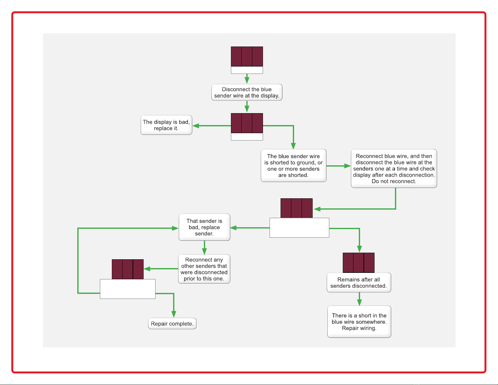
SHORT CIRCUIT S h t
Shows?
S h t
Remains?
S h t S h t
YES NO
YES NO
NOYES
S h t
Comes back on
when sender
reconnected?
Disappears
when a sender is
disconnected?

Page 16SeeLeveL II 709 Series Display Manual
Troubleshooting & Installation Tips
What to do if the system freezes or is unresponsive
If the display is unresponsive, it may be “hung” due to a static discharge or electrical
noise. Try rebooting it by shutting o the 12V power to it for a few seconds, then
turning it back on.
What to do if operation becomes erratic or stops completely
Make sure all wiring connections are solid. Do not use spade connectors to join
wiring as they will degrade over time. Use insulated crimp-on butt connectors or
solder and insulate the wire connections.
What to do in dual console systems if the two displays do not read the same
For dual display console applications, if the consoles disagree the most likely
reason is a bad console ground. Both console grounds, and the sender grounds,
must be connected together with ground wiring. Do not depend on metal chassis
components. See item 2 in the following section for further details.
What to do if readings jump or are inaccurate
1. We have had a few instances where 120VAC interference has caused the
readings to stall and create a gap; readings would skip from 50% to 70% and
then begin to function again. The cause was wiring between consoles and
senders being tied too close to entrance boxes for shore power or bundled with
other high AC voltage lines or junction boxes.
2. Always ground the senders and the console to the same ground circuit. This is
very important; RV’s can have several ground circuits with resistance between
them. We have had instances where two consoles are installed with a dierent
ground for the service bay console and interior console. If you see dierent
levels from each console on the same tank, then the ground circuit is not
common. Connect both consoles to the same ground back to the breaker
panel ground point.
What to do if the system indicates a residual or non-zero water level even
though the tank is drained completely
1. This can be due to a convex tank bottom or a sloped tank bottom. In the case
of the convex bottom tank a ring of water may remain after draining. In the
case of the sloped bottom (to the drain valve side) a very small amount of
water left in the tank will result in a non-zero level indication. In both of these
cases, temporary installation of the sender using duct tape or masking tape will
allow the installer to check the tank level before committing to a nal sender
position. After cutting the sender to length and connecting the wires, be
sure to tape down both sides of the sender to eliminate air gaps between the
sender and tank surface which can cause low signal strength and unpredictable
performance. The ends of the sender must be at least ¼” to ½” away from the
tank bottom and top to allow for wall thickness. The exterior bottom & top
of the tank are not the same as the interior bottom & top; depending on the
tank wall thickness the inside height is ½” to 1” shorter than the outside height.
Knowing the wall thickness of your tank will allow you to nd the optimal
sender position; placing the sender where it can “see” the water will ensure
proper level calculation and sender operation.
2. The signal strength should be in the 50% range for best performance. If the
signal strength is in the 20% range it is indicative of a high resistance in a
connector, a bad ground, or improper bonding of the sender to the tank (a
possible air gap on one or both sides of the sender).
3. With the console installed you can check the level on each tank, if you get an
indicated level of 10% to 20% and you know this is too high, reposition the
sensor board as follows:
4. The close proximity of metal to the sender can be misinterpreted as water,
since they have similar electrical characteristics. Any metal such as steel,
aluminum, copper, or brass can aect the sender reading if it is closer than
about 2” from the face of the sender. If there are metal frame pieces, brackets,
straps, pipes, ducts, etc. close to the sender you may have to move the sender
away from them. Again, trial positioning using tape is necessary until the
problem disappears. Flexible pieces of metal can be held away from the sender
with rubber wedged between the sender and the metal. If the metal is o
to the side of the sender, or just butting to the edge then it is usually not a
problem, particularly on the right hand side of the sender.
5. Make sure that metal doors or covers are far enough away from the sender as
well, once everything is closed up the positioning may change. The symptoms
of exposure to large metal components are usually a non-zero reading when
the tank is empty, or the level appearing to jump suddenly as the tank is
drained or lled.
6. On fresh tanks there is sometimes a potential to not be able to use all the
water in the tank, we suggest you elevate the fresh sender 1” o the tank
bottom and position the top of the sender to allow for vent position (if the vent
is on the side of the tank). This way you should see ‘0’ before the pump starts
to suck air. Some tanks have a sump style draw system, in this case there is no
concern with unusable water, just allow for the wall thickness when positioning
the sender board (usually ½” to 1” margin from the outer shell). If the sender is
positioned above the vent then the maximum reading may be less than 100%.
7. There may be a buildup on the inside walls of black and grey tanks. We get
calls occasionally about older coaches that have not been in service for a few
years in which the black tank will now indicate a level even though it is empty.
The likely cause is that the tank has a signicant build-up, probably exceeding
¼” to ½” thick! Redex is not an acceptable chemical to promote clean tank
walls; it is far too slow to get the breakdown action started. Use an RV type
of liquid chemical, we suggest Tissue Digester, Sensor Cleaner, or the latest
we have used called Happy Campers Holding Tank Extreme Cleaner available
at www.happycampersworld.com. The next time you take a trip, leave with
WNOTE: In the case of a convex tank bottom, usually found on large at tanks,
raising the sender is the best solution to accomplish a zero reading when the
tank is empty. This may result in having to shorten the sender by an additional
segment.
On sloped tanks, which are used to promote complete draining, one alternative
is to measure the end of the tank opposite from the drain valve. It may be
necessary to extend the wire harness to be able to measure on the optimal side.
On the drain valve side, the best choice is to elevate the sender to avoid reading
a puddle at the drain valve.

Page 17SeeLeveL II 709 Series Display Manual
a high concentration of the chemical in the tank and approximately 30% full
of fresh water. Hopefully you can drive for 2-3 days allowing the tank levels
to rise through normal use. We recommend that you exceed the level that
you see the system report when the tank is empty. After the sloshing and the
soaking hopefully the build-up will be ushed away when the tank is drained
and ushed. If you still have symptoms the treatment may required a few more
times. The waste did not build up on the tank wall in one day, so it may not
dissolve in one treatment! The build-up looks like water to the system since it
holds a signicant volume of water in the build-up area. It takes much more
than a lm or piece of tissue to cause the error.
What to do if the system reads a zero water level at all times, or does not reach
100%
1. This may be due to excessive tank wall thickness. We have tested the sender
on an actual tank with 3/8“ wall thickness to ensure proper operation. If you
encounter an excessively thick tank wall the symptom will be a zero reading
regardless of the actual tank level. The cross check would be to test the sender
on another tank by taping it in place temporarily, if it now works the tank wall
thickness is well over 3/8”. You can also use a 1 gallon jug or a 5 gallon pail as
a test tank to crosscheck operation of the sender.
2. A symptom we have seen is the sender will not indicate 100% when the tank is
full. If the sender is positioned too high on the tank, then water cannot reach
high enough on the sender for it to read 100%. The top of the sender must be
at least ¼” to ½” away from the top of the tank to allow for wall thickness.
3. Another possibility is a tank wall thickness issue that may occur at the corners
or edges of the tank. This has not been a common issue, and the only
correction you can make is to move the board slightly lower, away from the
thick area.
What to do if sender delamination occurs
1. We have had reports of the senders literally falling o the tanks or showing
serious delamination. This is likely caused by a lack of tank surface preparation.
Surface prep is very simple, wipe the area to be adhered to with products like
Pro Bond, alcohol, or acetone. Do not use thinners because they leave residues
which attack the adhesive. Ambient temperatures of less than 60°F or 15°C
prevent the bonding agents in the adhesive from working properly; use a heat
gun to warm the tank surface if necessary. Also be sure the surface is dry, again
a heat gun is the best way to dry the bonding area. Finally, the surface of the
tank must be smooth. The adhesive works much better on smooth surfaces,
if necessary use an orbital sander with ne grit paper (220 grit) to quickly
accomplish the desired smoothness.
2. Another possibility is the wiring harness pulling on the sender. Make sure the
wiring to the tank sender is well supported so that it does not put a load on
the sender. Be sure to support all connecting harnesses; do not let the board
support the harness, this will in time cause delamination of the board from
the tank. One simple way to do this is to use Gorilla tape across the top of the
sender at a 90 degree angle to the sender orientation, with the wiring held in
place by the tape. The wires from the sender must be routed straight up or to
the right for reliable operation.
How to protect the sender from road spray and debris
3. On installations where the holding tank is exposed to under chassis road spray
and ying rocks etc. we recommend the use of an auto body undercoat, which
is easily purchased in auto parts stores. This tar based material clings well to
the senders and protects from water and debris.
4. One material in particular is 3M Professional Grade Rubberized Undercoating,
product code 03584. Another product that works well is a Dominion Sure Seal
rubberized undercoating such as Gravel Guard Rocker Guard Coating.
5. After the system is completed and tested apply the undercoat over the
complete board using two coats. Do not use lacquer, enamel paint, or plastic
paint for auto bumpers as these contain chemicals that will dissolve the
conformal coating on the board and cause malfunctions.
How to avoid damaging the display when mounting
1. If mounting the display in a metal panel or wall there is a risk of permanent
damage due to a jagged opening or too small of an opening. The metal panel
can short-circuit the display rendering it inoperable and requiring the installer
to replace it. Ensure that the edges of the cutout are smooth and that no
material is bent outward where it can dig into the display. Make sure that the
cutout is large enough so that the display can be easily inserted without having
to angle it. There is a ½” border all around the display to cover the edge of the
hole, so if the hole is a bit larger than the minimum requirement it will still be
covered by the display.
2. When fastening the display to the panel, make sure that it is centered in the
hole and not resting on one edge.
3. Non-conductive mounting spacers are available to help prevent damaging the
display. Contact Garnet for further details.
How to avoid damaging the display or pump switch due to excessive current
1. Please be aware that the water pump switch circuit has a limitation on current
draw of 7.5 amps, some large pumps can draw over 10 amps. These high drain
pumps must use a relay or the display console printed circuit will overheat and
damage the display permanently.
2. If the 12V supply line from the electrical panel does not have a 7.5 amp
fuse rating, please be sure to install the supplied fuse holder with a 7.5 amp
automotive style fuse inline on the +12V red wire.

Page 18SeeLeveL II 709 Series Display Manual
WARRANTY & SERVICE INFORMATION
Find warranty claim process information refer to our support page on our
website:
DISCLAIMER OF WARRANTY ON HARDWARE
Garnet Instruments warrants equipment manufactured by Garnet to be free from defects in
material and workmanship under normal use and service for a period of one year from the date
of sale from Garnet or an Authorized Dealer. The warranty period will start from the date of
purchase or installation as indicated on the warranty card. Under these warranties, Garnet shall
be responsible only for actual loss or damage su ered and then only to the extent of Garnet’s
invoiced price of the product. Garnet shall not be liable in any case for labor charges for indirect,
special, or consequential damages. Garnet shall not be liable in any case for the removal and/or
reinstallation of defective Garnet equipment. These warranties shall not apply to any defects or
other damages to any Garnet equipment that has been altered or tampered with by anyone other
than Garnet factory representatives. In all cases, Garnet will warrant only Garnet products which
are being used for applications acceptable to Garnet and within the technical speci cations of the
particular product. In addition, Garnet will warrant only those products which have been installed
and maintained according to Garnet factory speci cations.
LIMITATION ON WARRANTIES
These warranties are the only warranties, expressed or implied, upon which products are sold by
Garnet and Garnet makes no warranty of merchantability or tness for any particular purpose in
respect to the products sold. Garnet products or parts thereof assumed to be defective by the
purchaser within the stipulated warranty period should be returned to the seller, local distributor,
or directly to Garnet for evaluation and service. Whenever direct factory evaluation, service or
replacement is necessary, the customer must rst, by either letter or phone, obtain a Returned
Material Authorization (RMA) from Garnet Instruments directly. No material may be returned
to Garnet without an RMA number assigned to it or without proper factory authorization. Any
returns must be returned freight prepaid to: Garnet Instruments, 286 Kaska Road, Sherwood Park,
Alberta, T8A 4G7. Returned warranted items will be repaired or replaced at the discretion of Garnet
Instruments. Any Garnet items under the Garnet Warranty Policy that are deemed irreparable by
Garnet Instruments will be replaced at no charge or a credit will be issued for that item subject to
the customer’s request.
If you do have a warranty claim or if the equipment needs to be serviced, contact the installation
dealer. If you do need to contact Garnet, we can be reached as follows:
CANADA UNITED STATES
Garnet Instruments Garnet US Inc.
286 Kaska Road 5360 Granbury Road
Sherwood Park, AB T8A 4G7 Granbury, TX 76049
CANADA USA
www.garnetinstruments.com/support/
NOTES:
_______________________________________________________________________________
_______________________________________________________________________________
_______________________________________________________________________________
_______________________________________________________________________________
_______________________________________________________________________________
_______________________________________________________________________________
_______________________________________________________________________________
_______________________________________________________________________________
_______________________________________________________________________________
_______________________________________________________________________________
_______________________________________________________________________________
_______________________________________________________________________________
_______________________________________________________________________________
_______________________________________________________________________________
_______________________________________________________________________________
_______________________________________________________________________________
_______________________________________________________________________________
_______________________________________________________________________________
_______________________________________________________________________________
_______________________________________________________________________________
_______________________________________________________________________________
_______________________________________________________________________________
_______________________________________________________________________________
_______________________________________________________________________________
_______________________________________________________________________________
This manual suits for next models
13
Table of contents
Popular Tank Equipment manuals by other brands

TransTank
TransTank TransLoc Product handbook

Morrison
Morrison 915 Series Installation, operation and maintenance instructions

Trane
Trane RSDT1000F0 Installation, operation and maintenance

Alfalaval
Alfalaval GJ 10 instruction manual

Alfalaval
Alfalaval Toftejorg SaniJet 20 instruction manual

Graf
Graf Carat series Installation and maintenance instructions


