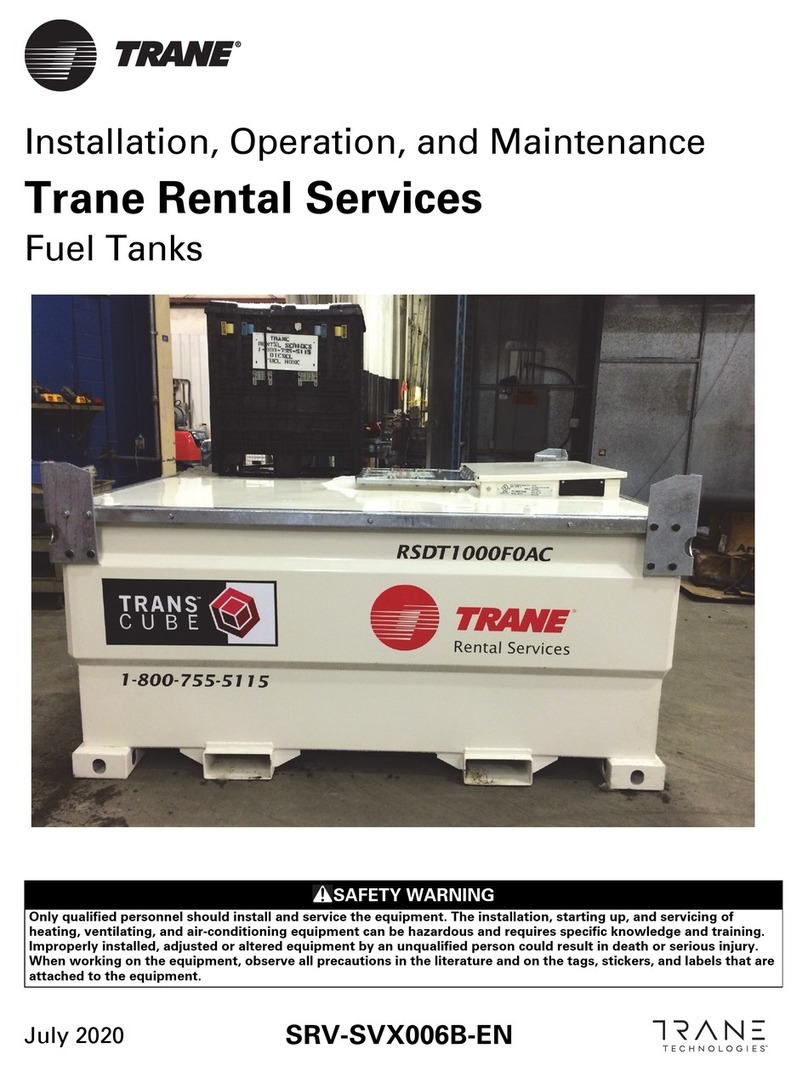
Trane RSDT1000F0 Installation and operating instructions

Trane Rental Services
Fuel Tanks
Installation, Operation, and Maintenance
May 2022 SRV-SVX006C-EN
SAFETY WARNING
Only qualified personnel should install and service the equipment. The installation, starting up, and servicing of
heating, ventilating, and air-conditioning equipment can be hazardous and requires specific knowledge and training.
Improperly installed, adjusted or altered equipment by an unqualified person could result in death or serious injury.
When working on the equipment, observe all precautions in the literature and on the tags, stickers, and labels that are
attached to the equipment.

©2022 Trane SRV-SVX006C-EN
Introduction
Read this manual thoroughly before operating or
servicing this unit.
Warnings, Cautions, and Notices
Safety advisories appear throughout this manual as
required. Your personal safety and the proper operation of
this machine depend upon the strict observance of these
precautions.
Important Environmental Concerns
Scientific research has shown that certain man-made
chemicals can affect the earth’s naturally occurring
stratospheric ozone layer when released to the
atmosphere. In particular, several of the identified
chemicals that may affect the ozone layer are refrigerants
that contain Chlorine, Fluorine and Carbon (CFCs) and
those containing Hydrogen, Chlorine, Fluorine and
Carbon (HCFCs). Not all refrigerants containing these
compounds have the same potential impact to the
environment. Trane advocates the responsible handling
of all refrigerants-including industry replacements for
CFCs and HCFCs such as saturated or unsaturated HFCs
and HCFCs.
Important Responsible Refrigerant
Practices
Trane believes that responsible refrigerant practices are
important to the environment, our customers, and the air
conditioning industry. All technicians who handle
refrigerants must be certified according to local rules. For
the USA, the Federal Clean Air Act (Section 608) sets forth
the requirements for handling, reclaiming, recovering and
recycling of certain refrigerants and the equipment that is
used in these service procedures. In addition, some states
or municipalities may have additional requirements that
must also be adhered to for responsible management of
refrigerants. Know the applicable laws and follow them.
The three types of advisories are defined as follows:
WARNING Indicates a potentially hazardous
situation which, if not avoided, could
result in death or serious injury.
CAUTIONsIndicates a potentially hazardous
situation which, if not avoided, could
result in minor or moderate injury. It
could also be used to alert against
unsafe practices.
NOTICE Indicates a situation that could result in
equipment or property-damage only
accidents.
WARNING
Proper Field Wiring and Grounding
Required!
Failure to follow code could result in death or serious
injury. All field wiring MUST be performed by qualified
personnel. Improperly installed and grounded field
wiring poses FIRE and ELECTROCUTION hazards. To
avoid these hazards, you MUST follow requirements for
field wiring installation and grounding as described in
NEC and your local/state/national electrical codes.
WARNING
Personal Protective Equipment (PPE)
Required!
Failure to wear proper PPE for the job being undertaken
could result in death or serious injury. Technicians, in
order to protect themselves from potential electrical,
mechanical, and chemical hazards, MUST follow
precautions in this manual and on the tags, stickers,
and labels, as well as the instructions below:
• Before installing/servicing this unit, technicians
MUST put on all PPE required for the work being
undertaken (Examples; cut resistant gloves/sleeves,
butyl gloves, safety glasses, hard hat/bump cap, fall
protection, electrical PPE and arc flash clothing).
ALWAYS refer to appropriate Safety Data Sheets
(SDS) and OSHA guidelines for proper PPE.
• When working with or around hazardous chemicals,
ALWAYS refer to the appropriate SDS and OSHA/
GHS (Global Harmonized System of Classification
and Labeling of Chemicals) guidelines for
information on allowable personal exposure levels,
proper respiratory protection and handling
instructions.
• If there is a risk of energized electrical contact, arc, or
flash, technicians MUST put on all PPE in accordance
with OSHA, NFPA 70E, or other country-specific
requirements for arc flash protection, PRIOR to
servicing the unit. NEVER PERFORM ANY
SWITCHING, DISCONNECTING, OR VOLTAGE
TESTING WITHOUT PROPER ELECTRICAL PPE AND
ARC FLASH CLOTHING. ENSURE ELECTRICAL
METERS AND EQUIPMENT ARE PROPERLY RATED
FOR INTENDED VOLTAGE.

Introduction
SRV-SVX006C-EN 3
Copyright
This document and the information in it are the property of
Trane, and may not be used or reproduced in whole or in
part without written permission. Trane reserves the right
to revise this publication at any time, and to make changes
to its content without obligation to notify any person of
such revision or change.
Trademarks
All trademarks referenced in this document are the
trademarks of their respective owners.
Revision History
Updated Model Number Description, General
Information, Day Tank Operation chapters.
WARNING
Follow EHS Policies!
Failure to follow instructions below could result in
death or serious injury.
• All Trane personnel must follow the company’s
Environmental, Health and Safety (EHS) policies
when performing work such as hot work, electrical,
fall protection, lockout/tagout, refrigerant handling,
etc. Where local regulations are more stringent than
these policies, those regulations supersede these
policies.
• Non-Trane personnel should always follow local
regulations.

4SRV-SVX006C-EN
Table of Contents
Model Number Descriptions . . . . . . . . . . . . . . 5
General Information . . . . . . . . . . . . . . . . . . . . . 6
Overview . . . . . . . . . . . . . . . . . . . . . . . . . . . . . 6
Unit Dimensions . . . . . . . . . . . . . . . . . . . . . . . . . 8
Day Tank - General Arrangement . . . . . . . 8
DEF Tank - General Arrangement . . . . . . . 8
Installation and Decommission . . . . . . . . . . . 9
Transportation . . . . . . . . . . . . . . . . . . . . . . . . . . 9
Day Tank Operation . . . . . . . . . . . . . . . . . . . . . 10
Day Tank To Generator Hose Connections 11
DEF Tank Operation . . . . . . . . . . . . . . . . . 12
DEF Tank Electrical Connections . . . . . . . 12

SRV-SVX006C-EN 5
Model Number Descriptions
Digit 1, 2 — Unit Function
RS = Rental Services prefix
Digit 3, 4 — Tank Type
DT = Day Tank
DD = DEF Tank
Digit 5, 6, 7, 8 — Tank Volume
0100
1000
Digit 9, 10 — Design sequence
FO
Digit 11, 12 — Incremental
designator
AA

6SRV-SVX006C-EN
General Information
The purpose of this IOM is to detail the proper handing,
installation, and maintenance recommendations for Trane
Rental Services Fuel Tanks. This equipment is designed
and manufactured for efficient refueling of equipment
and/or transportation of fuel. Full load lifting eyes, forklift
pockets, and internal baffles allow handling of the tank.
The double-walled design eliminates the need for spill
pans.
Overview
Each fuel tank is provided with a nameplate and labels with
the following information:
• Serial number
•Modelnumber
• Permissible pressures
• Permissible temperatures
•Weights
Table 1. Specifications
Specification RSDT1000F0 RSDD0100F0
Capacity (gal) 950 100
Double Wall Yes Yes
Day Tank Weight w/ out Fuel (lbs) 2800 772
Day Tank weight w/ Fuel (lbs) 9400 1742
Height (in) 48 33.6
Length (in) 91 45.5
Width (in) 87 45.5
Provided Hose Qty and Length (ft) (6) - 25 (1) - 25
Fuel Hose Connection Type Quick Couple Flare Fitting
Day Tank Supply and Return Qty and Size
(1) 1-in Supply (1) 2-in Supply
(1) 1-in Return N/A
Lifting Fork or Crane Fork or Crane
Transfer Pump Hose Length (ft) 25 25
Transfer Pump Power 12 Vdc 24 Vdc
UL Certification UL142 N/A
Canadian UL Certification S601 N/A

General Information
SRV-SVX006C-EN 7
Figure 1. Day tank components
A
B
C
DE
GH
I
F
AHatchlid
B Filler cap (3-inch)
CElectricpump
D Fuel feed line/valve
E Fuel return line/valve
F Refueling hose
GReliefvent
HFuelgauge
I Fuel feed line/with ball valve to fuel pump
Figure 2. DEF tank components
ABCDE
A 2-inch RSV Container valve
B2-inchSSVent
C2-inchPumpport
D2-inchPumpport
E Level gauge

8SRV-SVX006C-EN
Unit Dimensions
Day Tank - General Arrangement
DEF Tank - General Arrangement
1176.88 mm
46.33 in.
1155 mm
45.47 in.
1176.88 mm
46.33 in.
1155 mm
45.47 in.
534 mm
21.02 in.
534 mm
21.02 in.
902 mm
35.51 in.
853.50 mm
33.60 in.
783 mm
30.83 in.
1155 mm
45.47 in.
1155 mm
45.47 in.
1124 mm
44.25 in.
1124 mm
44.25 in.
102 mm
4.02 in.

SRV-SVX006C-EN 9
Installation and Decommission
Please read this document in its entirety before attempting
to off-load, install, or operate this tank.
Transportation
1. Turn off pump (move lever down) and close generator
port valves.
2. Check filler cap is on and closed securely.
3. Verify all outlets are securely closed/plugged with
plugs provided by the manufacturer.
4. Outer tank should be empty of spillage.
5. Close and padlock hatch to prevent vibration releasing
the catch.
6. Return all tank hoses and cable.
7. Secure for transportation.
WARNING
Heavy Objects!
Failure to follow instructions below could result in unit
dropping which could result in death or serious injury,
and equipment or property-only damage.
Ensure that all the lifting equipment used is properly
rated for the weight of the unit being lifted. Each of the
cables (chains or slings), hooks, and shackles used to
lift the unit must be capable of supporting the entire
weight of the unit. Lifting cables (chains or slings) may
not be of the same length. Adjust as necessary for even
unit lift.

10 SRV-SVX006C-EN
Day Tank Operation
• Use only for the transport of diesel fuel for refueling
equipment or standby generators.
• Keep the tank level when filling.
• Fill only with a hand-held trigger nozzle. Take special
care not to spill any fuel on the ground or in the
interstice.
• Do not smoke when refueling. Keep sparks flames and
hot material away from fuel and tank.
• Do not overfill; 95 percent is the maximum legal limit.
• Always replace filler cap and turn pump off (lever
down) when refueling finished.
• Close all valve outlets and lock lid when transporting
on a public highway.
• Check for fluid in outer tank and empty regularly. Refer
to maintenance manual for detailed procedure.
• Day tank can only be utilized as a “stand-alone” fuel
supply without using the generator's on-board fuel
tank or can be used to “manually refuel” the generator
fuel tank.
If Day Tank is used for manual refueling:
1. The day tank hand pump will have to be utilized for
refueling the generator's on-board fuel tank.
2. Place fuel tank in a place where it can be leveled as
much as possible.
3. Unlock and open hatch lid.
4. Pull out refueling hose and nozzle, see Figure 3 below.
5. Extend it to the tank to be refueled.
6. Connect the quick coupler on the pump discharge.
7. Open fuel feed line/valve on fuel tank.
8. Connect a power supply to the pump (minimum 20
amp rating).
9. Turn the pump on by lifting lever located on the side of
the pump.
10. Use the hand-held nozzle to transfer the fuel.
11. Fill to no more than 95 percent of capacity. This is the
maximum allowed in order to account for fuel
expansion. Do not overfill.
12. Turn the pump off when the refueling is completed.
If Day Tank is used as stand-alone constant
fuel supply:
The day tank will require a 12 Vdc generator battery power
supply for tank's on-board pump if being utilized for
“stand-alone” operation. Do not generator on-board tank
if day tank is utilized for stand-alone operation.
Supply
1. Place fuel tank in a place where it is level.
2. Connect the quick-coupler (see Figure 4) into feed line
on fuel tank.
3. Extend as much hose as required.
4. Connect swivel-type coupling (see Figure 7 below) into
generator supply connection.
5. Screw the quick-coupler with threaded end hose (see
Figure 5) into swivel coupler.
6. Bleed air from system.
Return
1. Connect the quick-coupler into the return line on the
fuel tank.
2. Extend as much hose as required.
3. Connect swivel-type coupling into generator return
connection.
4. Screw in the quick-coupler with threaded end hose
(see Figure 6) into swivel coupler.
Note: Valves on generator fuel tank should be placed
to draw fuel out of reservoir.
Note: Recommendations are for a 1 inch NPT thread.
Alternate connections require adapters
supplied by the customer.
WARNING
Flammable Fluids!
Failure to follow the safety requirements in this section
could result in death or serious personal injury, as well
as property damage due to fire or explosion. Diesel fuel
is flammable and poses a fire hazard. Do not expose the
fuel to excessive heat, pressure, or open flames or
sparks.
WARNING
Safety Requirements!
Failure to follow the safety guidelines in this section
could result in death or serious personal injury.

Day Tank Operation
SRV-SVX006C-EN 11
Day Tank To Generator Hose Connections
Figure 3. Hand nozzle
Figure 4. Quick coupler
Figure 5. Quick coupler to threaded end
Figure 6. Quick coupler to threaded end
Figure 7. Swivel-type coupling

Day Tank Operation
12 SRV-SVX006C-EN
DEF Tank Operation
The auxiliary Diesel Exhaust Fluid (DEF) Tank in figure
below can only be utilized in stand-alone mode with
automated pump control for refueling.
The auxiliary Diesel Exhaust Fluid (DEF) Tank heater
blanket utilizes a 120 Vac, 50 amp, 3-pin power cable
(figure below) for connection to generators. This cable
provide power for the tank heater blankets, which can be
used with TRS Cummins Tier-4 towable generator models
(140, 180, and 250 kW).
These DEF Tanks utilize a 24 Vdc remote fill system has a
14-pin plug connection (figure below). This 14-pin Deutsch
plug connector is utilized for activating the DEF Tank pump
when the generator DEF falls below 30% capacity, as well
as powers the heated DEF supply hose.
DEF Tank Electrical Connections
The 24 Vac, 14-pin Deutsch connector (P/N: HD36-18-14SN)
shall be used for power source connections typically from
2nd generation Cummins model generators (not 1st
generation). An adapter harness is required when TRS
DEF Tanks are paired with 1st generation Cummins model
generators.
1st Generation Cummins generators (100-275 kW
Towable) that have external DEF Connections utilize the 6-
Pin Deutsch connector (P/N: HD34-18-6PN) with pins as
shown in the figure below.
Figure 8. Pin identification for auxiliary DEF electrical
connector
1 DEF Pump Power Supply, 24 Vdc
2 DEF Pump Ground
3NotUsed
4NotUsed
5 DEF Line Heater Power Supply, 24 Vdc
6 DEF Line Heater Ground

Day Tank Operation
SRV-SVX006C-EN 13
2nd Generation Cummins generators (100-275kW
towable) that have external DEF connections utilize the 14-
Pin Deustch connector (P/N: HD34-18-14PN) w/ receptacles
as shown below.
Certain applications may require an adapter wiring
harness assemble to be created in the field if missing from
shipment inventory. This section provides detailed
instructions for the required parts to create the wiring
harness to interface with the generator. All required
assembly materials are listed in the DEF Tank Harness
BOM at the end of this section.
Assembly:
1. Crimp Socket Terminals (P/N: 0462-201-16141) to
four,16 AWG Wires on one end of the 2-foot length of
wire.
2. Insert terminals into generator Connector (P/N: HD36-
18-6SN) terminals 1, 2, 5 and 6. Note which wires are
used in which terminals on the connected.
3. Crimp pin terminals (P/N: 0460-202-16141) to four, 16
AWG on the opposite end of the 2-foot length of wire.
4. Insert pins into DEF Tank connector (P/N: HD34-18-
14PN) following the designations listed below.
Figure 9. Pin identification for auxiliary DEF electrical connector
A DEF Pump Power Supply, 24 Vdc
B DEF Pump Ground
CDEFLineHeaterGround
D DEF Line Heater Power Supply, 24 Vdc
E Cable Detection, Jumper Required in Customer Supplied Harness
F Cable Detection, Jumper Required in Customer Supplied Harness
G-P Not Used

Day Tank Operation
14 SRV-SVX006C-EN
5. Insert plugs into all open terminal locations on
connectors as shown in picture below.
6. Harness is now ready to use.
DEF Tank Harness BOM
Part # Description Qty Vendor
HD36-18-6SN Generator Side Connector 1 Mouser
0462-201-16141 #16 Socket Terminal 4 Mouser
114019-ZZ Large Seal Plug 2 Mouser
A114017-SR Small Seal Plug 12 Mouser
HD34-18-14PN DEF Tank Side Connector 1 Mouser
0460-202-16141 #16 Pin Terminal 4 Mouser
HDT-48-00 Crimpers / Crimping Tools TOOL HAND CRIMP SZ 20, 16 1 Mouser
0411-204-1605 PROBE TOOL EXTR SZ16 2 Mouser
N/A 16-4 SOOW Wire 2 Feet Local

Notes
SRV-SVX006C-EN 15

©2022 Trane
Trane has a policy of continuous product and product data improvement and reserves the right to change design and specifications without
notice. We are committed to using environmentally conscious print practices.
Trane - by Trane Technologies (NYSE: TT), a global climate innovator - creates comfortable, energy
efficient indoor environments for commercial and residential applications. For more information,
please visit trane.com or tranetechnologies.com.
SRV-SVX006C-EN 07 May 2022
Supersedes SRV-SVX006B-EN (Jul 2020)
This manual suits for next models
1
Table of contents
Other Trane Tank Equipment manuals
Popular Tank Equipment manuals by other brands

Alfalaval
Alfalaval Toftejorg SaniJet 20 instruction manual

Amtrol
Amtrol Therm-X-Trol ST-42V-C Installation, operation & service instructions

TransTank
TransTank SuperTrail Operator's handbook

Groth
Groth 7658A Installation, operation and maintenance

Vetus
Vetus FTL3808B Installation instructions and owner's manual