1-1
MAC/MTT-OPS-1
26 FEB 2019
SECTION 1
Definitions and Abbreviations
Contents
MANUAL USAGE
This technical manual only contains information
required to safely operate the MAC/MTT. See the
appropriate Maintenance and Operators Safety
Manual for specific vehicle system information and
maintenance procedures. If your system is not
covered in this manual please contact MEGA Corp.
Product Support Group at:
US toll free: 1-800-345-8889
Direct: 1-505-345-2661
Or visit our website at www.megacorpinc.com for
more detailed contact information.
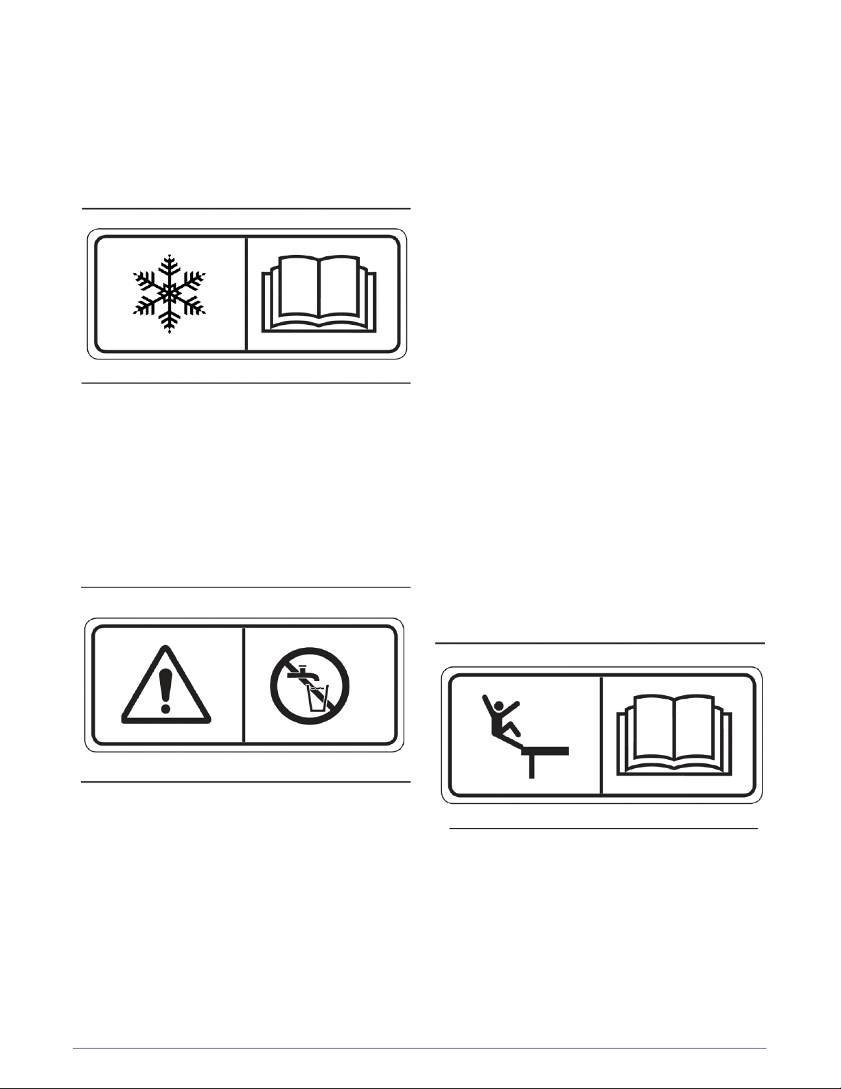
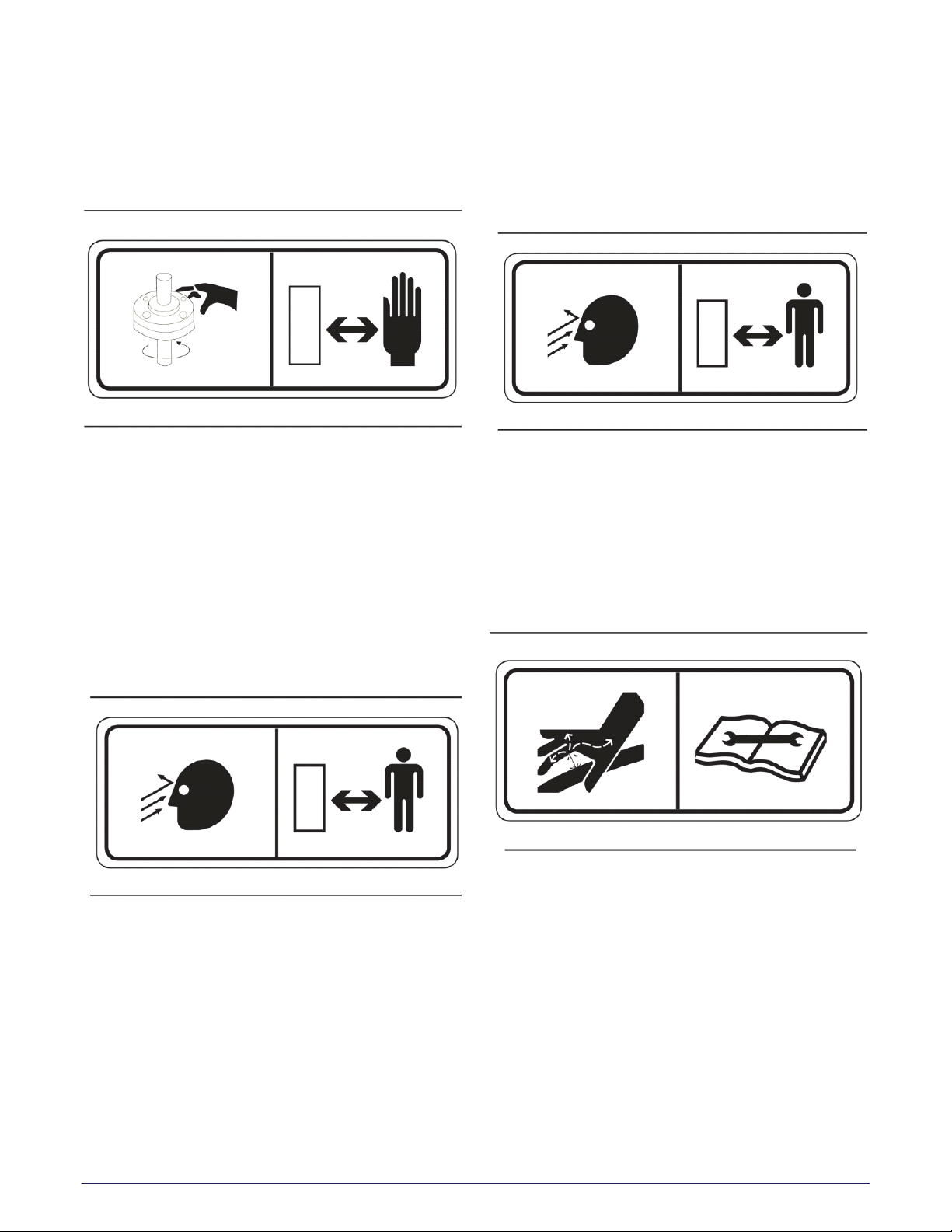
The exact location of the hazards and description
of the hazards are reviewed in this section. All
personnel working on or operating the MAC/MTT
must become familiarized with all the safety
messages.
Due to the nature of these processes, ensure that
all safety information, warnings and instructions
are read and understood before any operation or
any maintenance procedures are performed. Some
procedures take place with heavy components
and at moderate heights, ensure proper safety
procedures are maintained when performing
these actions. Failure to use and maintain proper
safety equipment and procedures will cause injury,
death or damage to equipment.
WARNING, CAUTION AND NOTES
The following definitions are found throughout
the manual and apply as follows:
Operating procedures and techniques, which
could result in personal injury and/or loss of life if
not carefully followed.
Operating procedures and techniques, which
could result in damage to equipment if not
carefully followed.
Operating procedures and techniques that are
considered essential to emphasize.
USE OF SHALL, WILL, SHOULD AND MAY
Shall and Will – Used when application of a
procedure is mandatory.
Should – Used when application of a procedure is
recommended.
May - Used to indicate an acceptable or suggested
means of accomplishment.
Manual Usage ................................................................1-1
Warning, Caution And Notes ....................................1-1
Use Of Shall, Will, Should And May .........................1-1
Safety Messages ............................................................1-2
Abbreviations ................................................................ 1-5
Symbology ......................................................................1-5
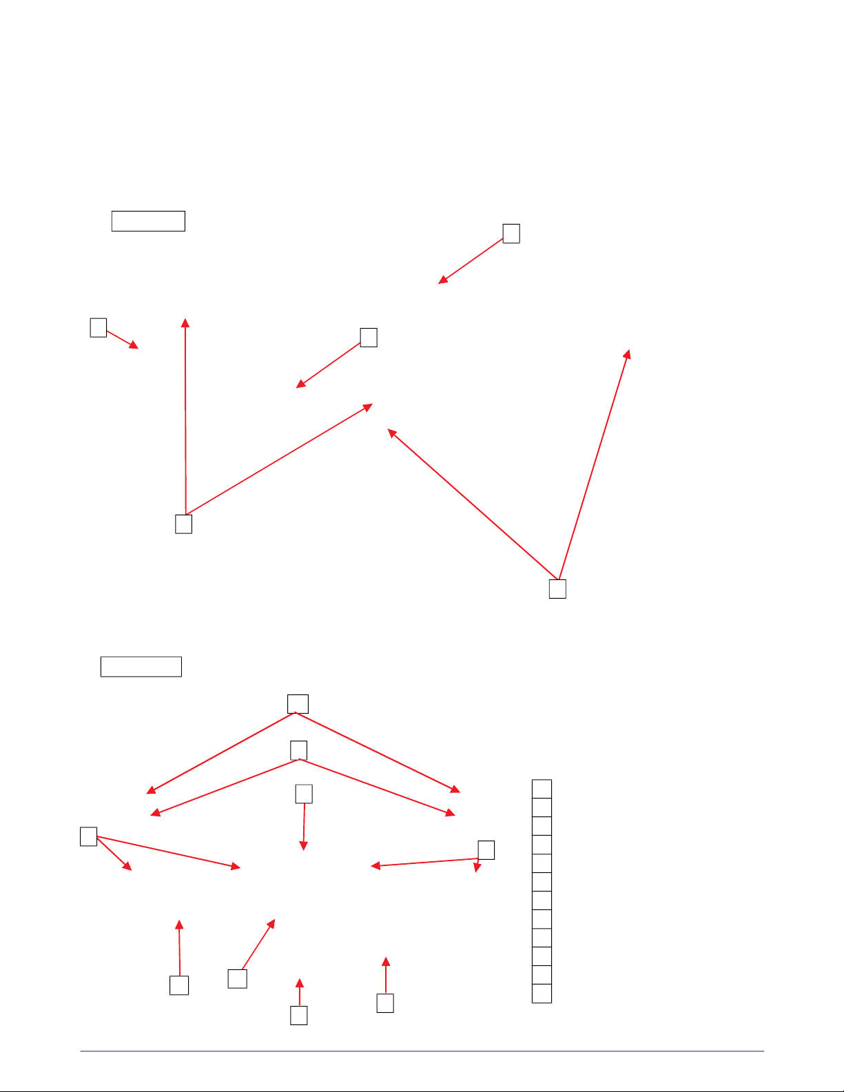
MAC/MTT Overview (Typical) ...................................1-6