Garrecht Avionik VT-01 User manual

Garrecht Avionik GmbH VT-01 Transponder Installation Manual - english -
Document: 01.0200.11E
Revision: 1.3 1
VT-01
Secondary Surveillance Radar
Transponder Mode-S
Installation Manual

Garrecht Avionik GmbH VT-01 Transponder Installation Manual - english -
Document: 01.0200.11E
Revision: 1.3 2
Record of Revisions
Always keep this page in front of this document.
Date Revision
Page(s)
Description of Change Inserted
by
11.08.05 1.0 all released JG
27.09.05 1.1 all Minor modifications in wording after review JG
12.01.06 1.2 all chapter 11, added:
- Information about setting up aircraft related data
JG
14.02.07 1.3 all new P/N VT-0104 (VT-01 UltraCompact) introduced JG

Garrecht Avionik GmbH VT-01 Transponder Installation Manual - english -
Document: 01.0200.11E
Revision: 1.3 3
1.Table of Contents
Record of Revisions.................................................................................................... 2
1. Table of Contents ................................................................................................... 3
2. Preface: .................................................................................................................. 5
3. Unpacking and part identification............................................................................ 5
3.1. VT-01: .............................................................................................................. 5
3.2. VT-01UltraCompact ......................................................................................... 6
4. Input Devices (human machine interface) .............................................................. 7
4.1. On/Off key........................................................................................................ 7
4.2. Ident key .......................................................................................................... 7
4.3. Mode-key ......................................................................................................... 7
4.4. Double shaft rotary encoder............................................................................. 7
5. Technical data and specifications........................................................................... 8
5.1. General ............................................................................................................ 8
5.2. Certification base ............................................................................................. 9
5.3. Equipment class............................................................................................. 10
5.4. Mode-S transponder level .............................................................................. 10
5.5. Equivalences to FAA TSO-C112 Classes:..................................................... 10
5.6. Limitations...................................................................................................... 10
5.7. Environmental categories............................................................................... 11
5.7.1. VT-01....................................................................................................... 11
5.7.2. VT-01 UltraCompact................................................................................ 12
5.8. Software level................................................................................................. 13
5.9. Telecommunication specifications.................................................................. 13
5.10. Logic of on-Ground interface........................................................................ 13
5.11. CAN-Bus interface ....................................................................................... 13
6. Aircraft installation ................................................................................................ 14
6.1. Installation VT-01 - single-block ..................................................................... 14
6.1.1. Assembling the steering unit and central unit: ......................................... 14
6.1.2. Panel mounting........................................................................................ 15
6.1.3. Static pressure connection ...................................................................... 15
6.1.4. Wiring ...................................................................................................... 16
6.2. Installation VT-01 - two-block......................................................................... 19
6.2.1. Installing the mounting kit / cradle ........................................................... 20
6.2.2. Panel mounting........................................................................................ 20
6.2.3. Static pressure connection ...................................................................... 20
6.2.4. Wiring ...................................................................................................... 21
6.2.5. Cradle handling ....................................................................................... 25
6.3. Installation VT-01 UltraCompact .................................................................... 27
6.3.1. Panel mounting........................................................................................ 27
6.3.2. Static pressure connection ...................................................................... 27
6.3.3. Wiring ...................................................................................................... 27
7. Antenna installation .............................................................................................. 30
7.1. General .......................................................................................................... 30
7.2. Special instructions for antenna installation in composite aircraft .................. 30
7.2.1. Mounting Preparation .............................................................................. 30
7.2.2. Ground Plane Size .................................................................................. 30
8. Antenna cable....................................................................................................... 31
9. Post installation configuration and setup .............................................................. 32
9.1. Setting up pilot specific data .......................................................................... 32

Garrecht Avionik GmbH VT-01 Transponder Installation Manual - english -
Document: 01.0200.11E
Revision: 1.3 4
9.1.1. Flight ID / aircraft registration................................................................... 32
9.1.2. Display contrast....................................................................................... 33
9.1.3. Display illumination.................................................................................. 33
9.2. Setting up password protected data............................................................... 34
9.2.1. Illumination .............................................................................................. 34
9.2.2. LCD contrast............................................................................................ 34
9.2.3. Power-up Mode ....................................................................................... 34
9.2.4. Aircraft data ............................................................................................. 35
10. Determining installed equipment performance ................................................... 38
10.1. Checking equipment installation................................................................... 38
10.2. Equipment performance............................................................................... 38
10.3. Flight test procedures................................................................................... 40
10.3.1. General.................................................................................................. 40
10.3.2. Flight tests instructions .......................................................................... 40
Appendix A - Dimensions ......................................................................................... 41
VT-01 Steering unit and System unit..................................................................... 41
VT-01 Mounting kit (with craddle) ......................................................................... 42
VT-01 UltraCompact ............................................................................................. 43
Appendix B ............................................................................................................... 44
Appendix C ............................................................................................................... 45
Assembling BNC/TNC plugs for AIRCELL 7 coaxial cable ................................... 45
Assembling the Sub-D Connectors for interconnection wiring .............................. 46

Garrecht Avionik GmbH VT-01 Transponder Installation Manual - english -
Document: 01.0200.11E
Revision: 1.3 5
2. Preface:
This manual contains installation information and instructions for the Mode-S transponder VT-01. It
shall be read before installing your VT-01 transponder.
The installation shall be carried out or supervised by a qualified person. Damage caused by
installation by unqualified persons is not covered by the manufacturers warranty.
Safety symbols:
The following symbols and terms are used in this manual:
Warning
Warning statements identify conditions or practices that could result in injury or
loss of life
Caution
Caution statements identify conditions or practices that could result in damage of
this product or other property.
Important note:
Indicates important or usefull information. It is strongly recommended to read,
understand and follow the statement.
3. Unpacking and part identification
3.1. VT-01:
The VT-01 transponder system is supplied with the following:
P/N: VT-0101-()-()-() Steering unit
P/N: VT-0102-()-()-()-070 Central unit Class 2 (71 Watt)
or VT-0102-()-()-()-125 Central unit Class 1 (125 Watt)
Document: 01.0200.10 User’s guide
Document: 01.0200.11 Installation manual (this document)
Available options:
P/N: VT-0103-1-()-() Mounting kit/wiring harness with installation cradle
(required for installation of VT-01 as a two block system with remote
steering unit. It also allows simple and quick installation and removal
of the central unit. VT-01UC cannot be installed as two block
systems).
P/N: VT-0103-2-()-() Mounting kit/wiring harness without installation cradle
Document: 01.0200.12 Maintenance and repair manual (for avionic repairshops only)

Garrecht Avionik GmbH VT-01 Transponder Installation Manual - english -
Document: 01.0200.11E
Revision: 1.3 6
3.2. VT-01UltraCompact
The VT-01 UltraCompact transponder system is supplied with the following:
P/N VT-0104-070 System unit
or VT-0104-070
P/N: VT-0103-2-()-() Mounting kit/wiring harness without installation cradle
Available options:
Document: 01.0200.12 for maintenance and repair manual (for avionic
repairshops only)
Garrecht Avionik GmbH VT-01 Transponder Installation Manual - english -
Document: 01.0200.11E
Revision: 1.3 7
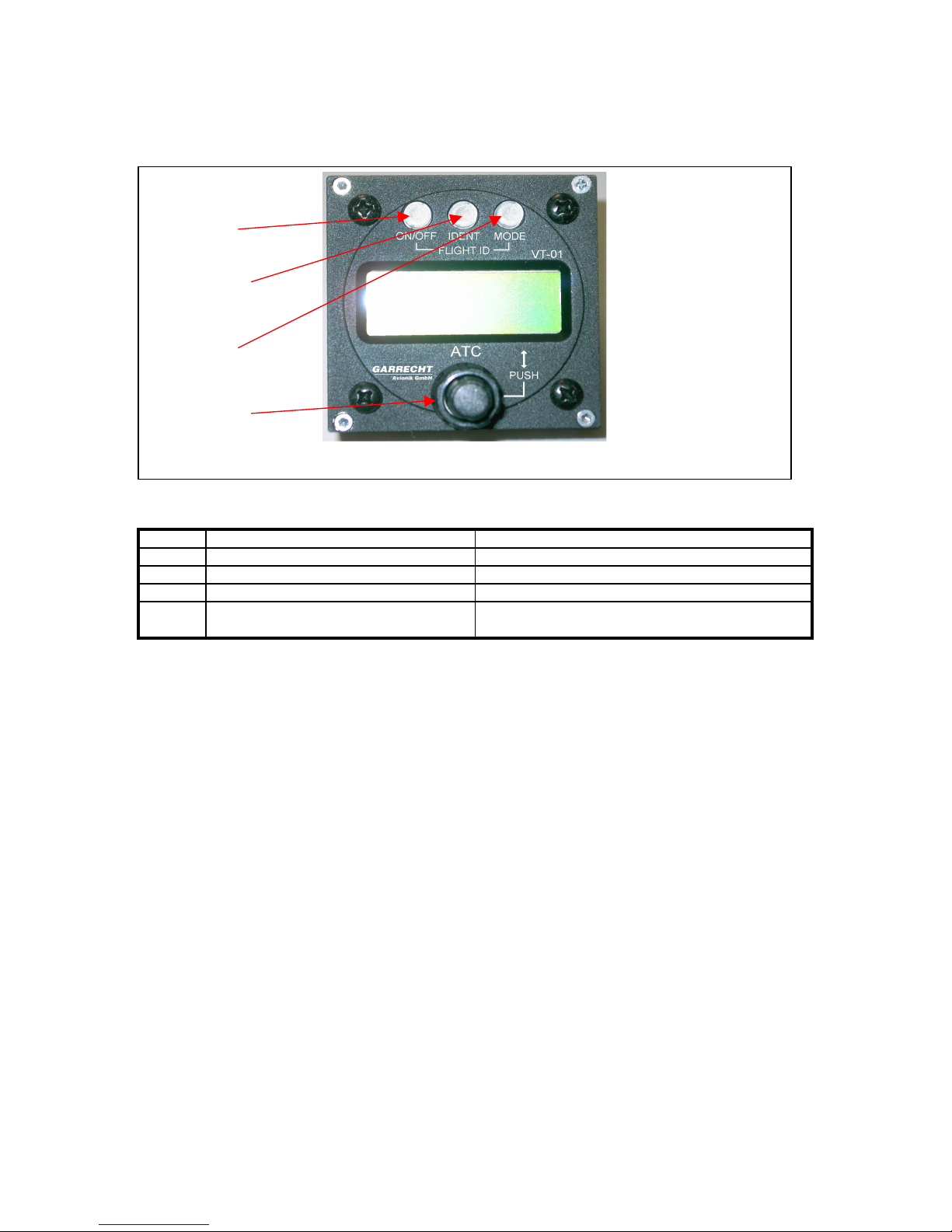
4.Input Devices (human machine interface)
Picture of front panel with Input devices
The system will be operated using the following devices:
Nr. Description Function
1 On/Off key Switches the system On or Off
2 Ident – key Invokes the Ident Mode for 18 sec.
3 Mode – key Selects the operating mode
4 Double shaft encoder with push on
capability for inner knob
Enters or modifies values
4.1. On/Off key
To enable the system, press key 1 shortly. After the start, the unit performs the built in test and shows
the operating mode. For switching off, press key 1 for at least 3 seconds Release the key, when the
LCD becomes blank
4.2. Ident key
Pressing key 2 invokes the ident mode for 18 seconds. Use this function only when the ATC requires
to sqawk ident.
4.3. Mode-key
Key 3 selects the following modes:
• SBY Standby - System is switched on, no replies or squitters will be sent.
• ON Selected reply code will be replied for Mode-A/C interrogations, altitude information is
set to zero, squittering is enabled, Mode-S interrogations will be replied
• ALT Selected reply code will be replied for Mode-A/C interrogations, altitude information is
set to indicated value, squittering is enabled, Mode-S interrogations will be replied
4.4. Double shaft rotary encoder
Main input device for setting values is the double shaft rotary encoder. Rotating the outer knob selects
the position to be modified. Rotating the inner knob changes the selected value.
The edit mode will be started rotating the inner or outer knob of the double shaft encoder.
Pushing the inner knob confirms the selected value and cancels the edit mode (cursor stops blinking).
1
2
3
4

Garrecht Avionik GmbH VT-01 Transponder Installation Manual - english -
Document: 01.0200.11E
Revision: 1.3 8
5.Technical data and specifications
5.1.General
Technical characteristics Data
Mechanical
VT-01
Dimensions
Mounting
Weights
VT-01 UltraCompact
Dimensions
Mounting
Weight
Steering unit :65x65x34,5 mm (w/o. connectors)
Central unit: 65x65x128 mm (w/o. connectors)
57 mm panel mount
Steering unit: 0,21 kg
Central unit: 0,61 kg
61,5 x 61,5 x 170mm
57 mm panel mount
0,57 kg
Environmental
Max. Altitude
Temperature
Cooling
Vibration
Shock
50.000 ft (internal alticoder limited to 40.000ft)
(see also limitiations chap. 5.6)
-20°C - +55°C
passive, no auxiliary cooling required
DO160D Cat. S, Curve M
Operational: 6g, crash safety: 20g
Electrical
Voltage (nom.):
Voltage (operational)
Current (nom.)
@ 13,8 V and 1200 A/C replies/sec.
Standby (sqitters active)
RF-power @ antenna
Replyrate:
Output Impedance
max. VSWR
13,8 V DC
9 to 32 V DC
VT-0102-()-()-()-070
VT-0104-070: 0,35 A
VT-0102-()-()-()-125
VT-0104-125: 0,45 A
VT-0102-()-()-()-070
VT-0104-070: 0,16 A
VT-0102-()-()-()-125
VT-0104-125: 0,17 A
VT-0102-()-()-()-070
VT-0104-070: > 70 Wp
VT-0102-()-()-()-125
VT-0104-125: > 125 Wp
min. 1200/s Mode-A/C
min. 50/s Mode-S
50 Ohms
1,5:1

Garrecht Avionik GmbH VT-01 Transponder Installation Manual - english -
Document: 01.0200.11E
Revision: 1.3 9
Interfaces:
Human machine interface / User input
capablity
The system provides 3 buttons and a twinaxle
rotary encoder for inputting values and selecting
operational modes. System messages and
entered values are displayed on a 2 lines / 12
characters LCD display.
Automatic input capability:
On Ground interface:
The system detects the input of an “on ground”
switch. If the aircraft’s frame does not supply
such an information, the input channel will be set
to “airborne” always (ref. to chapter 5.10).
Logic = 0: on ground condition
Suppression interface:
The system provides an suppression interface to
prevent interference with other instruments
installed in the same aircraft (such as DME):
Impedances:
DC: -0,4 V to + 30 V: 7,2 kOhms
DC: < -0,4 V: 1 kOhms
AC: 1 kOhms
Levels:
output: 10 V
input: 7 V - 30 V
Alitcoder capability
The system contains an integral digital alticoder
to provide data about pressure altitude for Mode
C information in 100 ft steps. It’s line has to be
connected to the aircraft’s static pressure
system.
Range: -1000ft to + 40.000ft
Self test routines (BIT)
After powering on, the system runs several
internal self test routines permanently. In case of
errors, the user gets warned visble and audible
and depending on the level of error, the system
stops operating with a permanent error
message.
5.2. Certification base
ETSO-2C112a
EUROCAE ED-73B

Garrecht Avionik GmbH VT-01 Transponder Installation Manual - english -
Document: 01.0200.11E
Revision: 1.3 10
5.3. Equipment class
Class 1: If using central unit VT-0102-()-()-()-125
If using system unit VT-0104-125
Class 2: If using central unit VT-0102-()-()-()-070
If using system unit VT-0104-070
5.4. Mode-S transponder level
Level 2se Mode-S transponder
5.5. Equivalences to FAA TSO-C112 Classes:
If using central unit VT-0102-()-()-()-125 or
If using system unit VT-0104-125: Equal to FAA TSO C112 Class: 2A1 120 010
If using central unit VT-0102-()-()-()-070 or
If using system unit VT-0104-070 Equal to FAA TSO C112 Class: 2B1 020 010
5.6.Limitations
1. To reach the required minimum RF peak power, the use of an antenna cable with a total loss
of less or equal 2,5 dB is required.
2. The range of the internal alticoder is limited to a maximum altitude of 40.000 ft.
3. The system using the CLASS 2 central unit (P/N: VT-0102-()-()-()-070) or the system unit
VT-0104-070 may be operated in aircraft not exceeding a maximum speed of 175 kts, a
maximum altitude of 15.000 ft and a MTOW of 5700 kg.
4. The system using the CLASS 1 central unit (P/N: VT-0102-()-()-()-125) or the system unit
VT-0104-125 may be operated in aircraft not exceeding a maximum speed of 250 kts, a
maximum altitude of 50.000 ft and a MTOW of 5.700 kg.

Garrecht Avionik GmbH VT-01 Transponder Installation Manual - english -
Document: 01.0200.11E
Revision: 1.3 11
5.7. Environmental categories
5.7.1. VT-01
Section Category Conditions
Temperature / Altitude D1 4.0 D1
Low ground survival temperature 4.5.1 D1 -55°C
Low operating temperature 4.5.1 D1 -20°C
High ground survival Temperature 4.5.2 D1 +85°C
High Short-time Operating Temperature 4.5.2 D1 +70°C
High Operating Temperature 4.5.3 D1 +55°C
In .Flight Loss of Cooling 4.5.4 Z No auxiliary cooling required
Altitude 4.6.1 D1 50.000 ft.*
Temperature Variation 5.0 B 5°C / minute
Humidity 6.0 A
Shock 7.0 B 6 G operational shocks
20 G crash safety
Vibration 8.0 S Vibration curve M
Explosion Profness 9.0 X
Water Profness 10.0 X
Fluids Susceptibilities 11.0 X
Sand and Dust 12.0 X
Fungus Resistance 13.0 X
Salt Spray 14.0 X
Magnetic Effect 15.0 Z Less than 0.3 m
Power Input (DC) 16.0 B
Voltage Spike Conducted 17.0 B
Audio Frequency Conducted Susceptibility 18.0 B
Induced Signal Susceptibility 19.0 A
Radio Frequency Susceptibility 20.0 T
Emission of RF 21.0 B compliant with CAT M except
of harmonics of 1090 MHz
Lightning Induced Transient Susceptibility 22.0 A2XXX
Lightning Direct Effects 23.0 X
Icing 24.0 X
Electrostatic Discharge (ESD) 25.0 A
* see chapter 5.6 for restrictions

Garrecht Avionik GmbH VT-01 Transponder Installation Manual - english -
Document: 01.0200.11E
Revision: 1.3 12
5.7.2. VT-01 UltraCompact
Section Category Conditions
Temperature / Altitude D1 4.0 D1
Low ground survival temperature 4.5.1 D1 -55°C
Low operating temperature 4.5.1 D1 -20°C
High ground survival Temperature 4.5.2 D1 +85°C
High Short-time Operating Temperature 4.5.2 D1 +70°C
High Operating Temperature 4.5.3 D1 +55°C
In .Flight Loss of Cooling 4.5.4 Z No auxiliary cooling required
Altitude 4.6.1 D1 50.000 ft.*
Temperature Variation 5.0 B 5°C / minute
Humidity 6.0 A
Shock 7.0 B 6 G operational shocks
20 G crash safety
Vibration 8.0 U2
R
Vibration curve F/F1
Vibration curve B/B1
Explosion Profness 9.0 X
Water Profness 10.0 X
Fluids Susceptibilities 11.0 X
Sand and Dust 12.0 X
Fungus Resistance 13.0 X
Salt Spray 14.0 X
Magnetic Effect 15.0 Z Less than 0.3 m
Power Input (DC) 16.0 B
Voltage Spike Conducted 17.0 B
Audio Frequency Conducted Susceptibility 18.0 B
Induced Signal Susceptibility 19.0 A
Radio Frequency Susceptibility 20.0 S
T
radiated susc.
conducted susc.
Emission of RF 21.0 B compliant with CAT M except
of harmonics of 1090 MHz
Lightning Induced Transient Susceptibility 22.0 A2XXX
Lightning Direct Effects 23.0 X
Icing 24.0 X
Electrostatic Discharge (ESD) 25.0 A
* see chapter 5.6 for restrictions
Garrecht Avionik GmbH VT-01 Transponder Installation Manual - english -
Document: 01.0200.11E
Revision: 1.3 13
5.8. Software level
The software level for VT-01 has been determined to be
Level D:
Software whose anomalous behavior, as shown by the system safety assessment process,
would cause or contribute to a failure of system function resulting in a minor failure condition
for the aircraft.
5.9. Telecommunication specifications
Emission power: with central unit VT-0102-()-()-()-125 or
system unit VT-0104-125: 250 Watts max.
with central unit VT-0102-()-()-()-070 or
system unit VT-0104-070: 200 Watts max.
Emission class: 12M0M1D
Frequency: 1090 MHz
5.10. Logic of on-Ground interface
The transponder has an on-ground interface, which should be connected to your aircraft installation, if
an adequate signal will be provided. The following table shows the system behaviour for different
configurations and input at the interface
on ground configuration in Menu
on ground switch settings
NO YES
no on-ground switch present airborne -
on ground - on ground
airborne - airborne
on ground: system replies not to Mode-A/C and Mode-S "all-call" interrogations, squitters active
airborne: system replies to all interrogations, squitters active
Do not install an manual on ground switch in the cockpit of your aircraft. If no
adequate on ground switch is provided in the airframe, leave the on ground
input unconnected.
5.11.CAN-Bus interface
The system provides a CAN-Bus interface for communication between steering unit and
central unit. A detailed description of the interface can be obtained by the manufacturer (for
system integrators or OEMs only).
Garrecht Avionik GmbH VT-01 Transponder Installation Manual - english -
Document: 01.0200.11E
Revision: 1.3 14
6. Aircraft installation
The VT-01 provides maximum levels of flexibility. Depending on the space in your cockpit you can
have a single-block or two-block equipment installation. The two-block system requires a mounting
kit/cradle (PN # VT-0103-1-()-() ) to carry the central unit. It allows a quick installation and removal of
the complete central unit without using tools. If each aircraft in a fleet carries a steering unit and a
mounting cradle, the central unit can be interchanged between all aircraft. All aircraft related data is
stored in the steering unit, which always remains in an aircraft.
General: All installation work shall be performed in accordance with the
acceptable methods, techniques and practices for aircraft alterations,
inspections and repair, shown in FAA documents AC 43.13-1B and AC 43.13-
2A (see www.faa.gov to obtain this documents free of charge in digital form).
6.1. Installation VT-01 - single-block
To install as a single-block system, the following steps need to be performed:
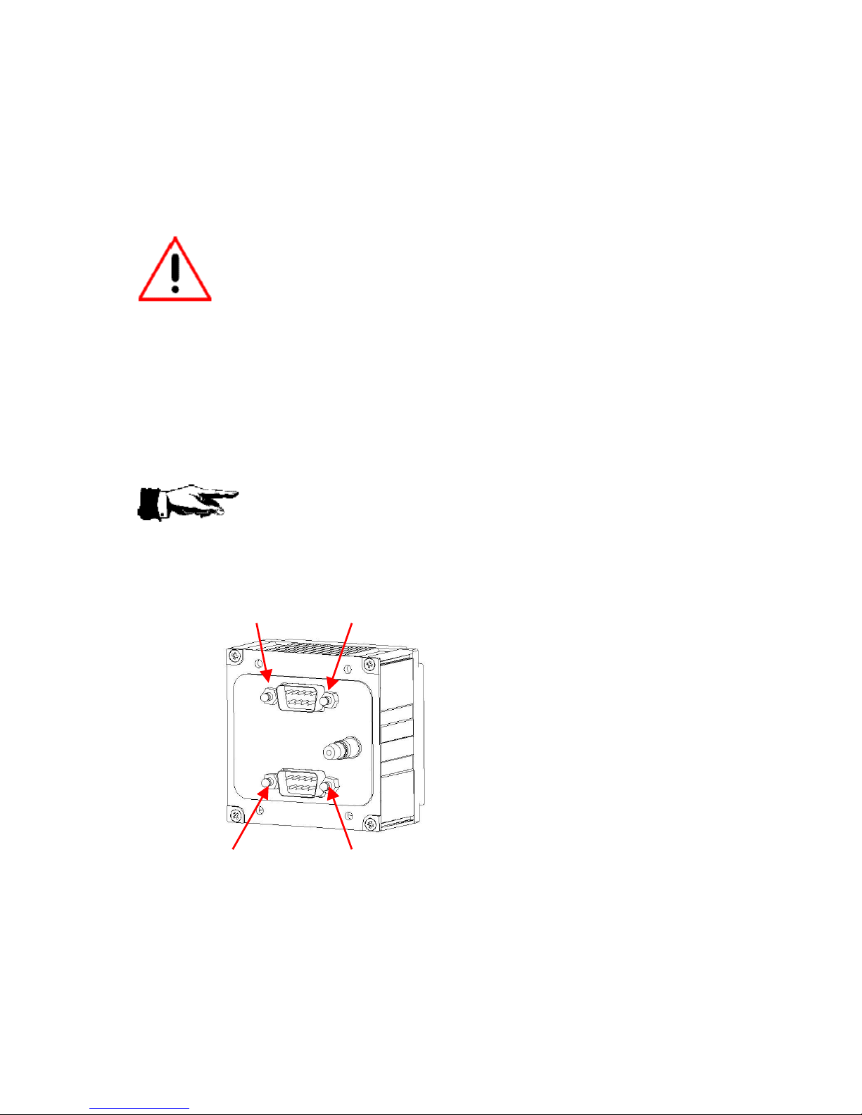
6.1.1. Assembling the steering unit and central unit:
Before attaching the steering unit to the central unit, Check if the pressure
connector, the steering unit plug and the central unit plug are clean. If not,
remove all foreign bodies from the parts.
Replace the Quicklock
terminals in the back of the
steering unit with screws (4-
40), if installed.
Rear view of steering unit

Garrecht Avionik GmbH VT-01 Transponder Installation Manual - english -
Document: 01.0200.11E
Revision: 1.3 15
Replace the screws (4-40) in the back of
the central unit with quicklock terminals, if
installed
Rear view of central unit
1. Assemble mating pressure
connector and plug for both units
in the correct orientation
2. Push the steering unit (1) onto the
central unit (2) . Use the 4 screws
(3) to fasten both units.
6.1.2. Panel mounting
Determine a suitable position in the instrument panel that is in view of the pilot in command.
When choosing a position for installation, always be sure not to damage structural devices of
the airframe.
Cut a 57mm (2 ¼ inch) diameter hole with 4 x 4.1mm holes for the mounting screws (see chapter 15
for detailed locations). A minimum space of 65.5mm x 65.5mm behind the panel cut out is required for
clearence with adjacent instruments. A depth of 205mm is recommended to accomodate the
transponder and electrical connectors.
6.1.3. Static pressure connection
The system contains an integral alticoder. Connect the static pressure line of the aircraft to the
connector on back of the central unit.
Front of central unit

Garrecht Avionik GmbH VT-01 Transponder Installation Manual - english -
Document: 01.0200.11E
Revision: 1.3 16
The integral alticoder supplies data immediatly after switching on the VT-01. No warm up period is
required. For calibration of the internal alticoder, an instruction will be provided by the manufacturer to
qualified installers.
6.1.4. Wiring
Wiring electrical components shall be performed by qualified personal only to
prevent damages and hazardous situations that could result in loss of life.
All wires (except the antenna line) related to the VT-01 in single-block configuration
are connected to one SUB-D 9 pin connector on the back of the central unit.
Ensure that the Sub-D connector is fastened to the housing of the central unit
correctly before operating the unit in flight.
The following subchapters describe the different lines required for operating the transponder.
DO NOT POWER ON THE TRANSPONDER WITH THE ANTENNA
DISCONNECTED !!!
Damage to the RF unit caused by a disconnected antenna can be
determined by the manufacturer and is not covered by the manufacturers warranty.
Garrecht Avionik GmbH VT-01 Transponder Installation Manual - english -
Document: 01.0200.11E
Revision: 1.3 17
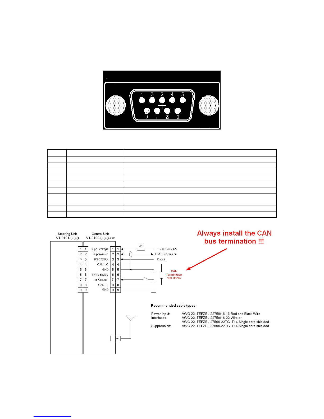
6.1.4.1. Connector wiring
Wire the female plug to be connected to the connector (CN3) on the back of the central unit as
described in the following table. Refer to chapter 17 for a proper cable installation and assembling of
the connector.
viewed from the back of the SUB-D 9 female connector
Pin Function Additional Information
1 +9V - + 28V DC Connect to aircraft primary power source
2 mutual suppression Connect to DME suppression bus (use shielded line)
3 RS-232 RX For ADS-B (Data in)
4 CAN-LO Not used in single-block installation, terminate as shown below
5 GND Connect to common GND of airframe
6 Pwr_enable Not used in single-block installation, do not connect
7 On Ground Do not connect, if no on-ground signal is provided by aircraft
installation
8 CAN-HI Not used in single-block installation, terminate as shown below
9 GND Connect to common GND of airframe

Garrecht Avionik GmbH VT-01 Transponder Installation Manual - english -
Document: 01.0200.11E
Revision: 1.3 18
6.1.4.2. Power supply
The transponder is supplied by the aircrafts’s primary power source (10 V to 28 V DC). The system
provides protection against reverse polarity. Always install a Fuse !!!
6.1.4.3. Suppression interface
The suppression line needs to be wired to other avionic components working in the 962..1213 MHz
frequency band, such as DME or TACAN, to suppress any replies from the transponder that void the
capabilty of such systems while operating.
The suppression line provides IN and OUT capability to prevent data transmission either to the
transponder or other equipment.
Wiring the suppression line requires a qualified avionic technician or
engineer to prevent any kind of malfunction of the installed equipment. All
equipment connected to the suppression line must be re-inspected and re-
approved before operation. Refer to chapter 5 for specifications of the
suppression interface.
6.1.4.4. On-ground interface
If your aircraft installation provides an on-ground signal, it should be connected to this pin. The
tranponder replies only to discretely addressed Mode-S interrogations if the on-ground signal is
present. The permament emission of squitters will not be effected.
Refer to chapter 5.10 for logic table of this interface.
6.1.4.5. RS-232 interface
This interface is intended for ADS-B applications. It may be used for connecting a GPS receiver to
broadcast the current position with extended squitters.
Minimum recommended NMEA sentences are $GPRMC, $GPGGA, $GPGSA. The baud rate is 4800
bps.
6.1.4.6. CAN-Bus interface
The CAN-Bus interface is used for communication between steering unit and
central unit. If the one-block configuration will be installed, a resistor (100
ohms) must be used for proper termination of the bus. A missing termination
results in COMM error and malfunction of the system.
For pinout refer to the wiring diagram shown on the previous page.
6.1.4.7. Antenna connection
Connect the BNC plug of the antenna line to the connector in the back of the central unit. Be sure that
the plug has been fastened to prevent disconnection caused by vibration
DO NOT POWER ON THE TRANSPONDER WITH THE ANTENNA
DISCONNECTED !!!
Damage to the RF unit caused by a disconnected antenna can be
determined by the manufacturer and is not covered by the manufacturers warranty.
Refer to chapter 9 for details about installing a transponder antenna in your aircraft.

Garrecht Avionik GmbH VT-01 Transponder Installation Manual - english -
Document: 01.0200.11E
Revision: 1.3 19
6.2. Installation VT-01 - two-block
To install as a two-block system, the following steps need to be performed:
Unfasten the 4 Screws (3) and remove the
steering unit (1) from the central unit (2).
Fasten a shoulder washer (5) with
screws (4) on each side of the central
unit.
Replace the quick lock terminals in back
of the central unit with screws.
Rear view of central unit
Front of central unit
Front of central unit

Garrecht Avionik GmbH VT-01 Transponder Installation Manual - english -
Document: 01.0200.11E
Revision: 1.3 20
Replace the screws in the back of the
steering unit with quick lock terminals.
Rear view of steering unit
6.2.1. Installing the mounting kit / cradle
Select a suitable place for installation of the mounting kit / cradle (P/N # VT-0103-1-()-() ) in your
aircraft. Consider the space needed for inserting / removing the central unit. In order to remove make
sure it is possible to reach and operate the lock device on the end of the cradle .
The maximum distance between steering unit and central unit is limited by the data interface cable
used for communication between the system. It shall not exceed 10 metres in length.
Fasten the mounting kit to the airframe using 4 x M4x5 screws
6.2.2. Panel mounting
Determine a suitable position in the instrument panel that is in view of the pilot in command.
When choosing a position for installation, always be sure not to damage structural devices of
the airframe.
Cut a 57mm (2 ¼ inch) diameter hole with 4 x 4.1mm holes for the mounting screws (see chapter 15
for detailed locations). A minimum space of 65.5mm x 65.5mm behind the panel cut out is required for
clearence with adjacent instruments. A depth of 50mm is recommended to accomodate the steering
unit and electrical connectors.
6.2.3. Static pressure connection
The steering unit contains an integral alticoder. Connect the static pressure line of the aircraft to the
connector on back of the steering unit.
The integral alticoder supplies data immediatly after switching on the VT-01. No warm up period is
required. For calibration of the internal alticoder, an instruction will be provided by the manufacturer to
qualified installers.
Other manuals for VT-01
1
Table of contents
Other Garrecht Avionik Marine Radio manuals

Popular Marine Radio manuals by other brands

F.u.n.k.e.
F.u.n.k.e. TRT800H-LCD Operation and installation

Trig Avionics
Trig Avionics TT31 Modification Instructions

Garmin
Garmin VHF 300 - Marine Radio Quick reference guide

Sailor
Sailor UAIS1900 Technical manual

MicroAir Avionics
MicroAir Avionics T2000SFL user manual

stabo
stabo stabo RTM 100 quick start guide


