Gas Detection GTD-2000Tx User manual
GTD-2000Tx
Instruction Manual
Headquarters / Engineering research laboratory :
23 Gunpo Advance d Industry 1-ro(Bugok-dong), Gunpo-si, Gyeonggi-do
Tel +82-31-490-0800 Fax +82-31-490-0801
Yeongnam business office / Plant :
55 Gonghangap-gil 85beon-gil, Gangseogu, Busan Metropolitan City
Tel +51-973-8518 Fax +51-973-8519
www.gastron.com
Read in detail for correct use.

Gas & Flame
Detection System
GTD-2000Tx
Instruction Manual
www.gastron.com
02_03
In case of a problem after purchasing the product,
please contact the address below.
· Address : 23 Gunpo Advanced Industry 1-ro, Gunpo-si, Gyeonggi-do
· Tel : 031-490-0800
· Fax : 031-490-0801
· URL : www.gastron.com
The present product and the product manual can be changed without advance notice for performance improvement
and use convenience of the product.
* KOSHA GUIDE : P-135/6-2018
Calibration should be executed periodically at periods required by the manufacturer
¥'PSBDDVSBUFPQFSBUJPOPG(BTEFUFDUPSDIFDLVQBOEDBMJCSBUFGPSNPSFUIBOPODFJOFWFSZNPOUIT
( * In reference to KOSHA GUIDE: P-135/6-2018 / 7.2 In-house inspection, section 2)
¥'PSBDDVSBUFPQFSBUJPOPG(BTEFUFDUPSDIFDLVQBOEDBMJCSBUJPOXJUIDBMJCSBUJPOHBTCFGPSF
measurement is recommended.
¥8IFOOPUDBMJCSBUFEJUNBZDBVTFNBMGVODUJPOPGUIFFRVJQNFOUEVFUPQSPCMFNTSFTVMUJOHGSPN
Sensor aging.
¥8IFOUIFQSFTFOUJOTUSVNFOUTIPVMECFEJTNBOUMFEUIPTFXJUIQSPGFTTJPOBMTLJMMTGPS(BTEFUFDUPS
should conduct the operation.
¥'PSQPXFSTVQQMZDBCMFXJSFTQFDJGJDBUJPOTTIPVMECFEFUFSNJOFECZSFGFSSJOHUPUIFJUFNPG-FOHUI
PGJOTUBMMFEDBCMF
¥'PSUIFDPOUFOUTPODIFDLVQBOEDBMJCSBUJPOPG(BTEFUFDUPSQMFBTFVTFPVSDPNQBOZTFOHJOFFSJOH
department , e-mail, or web site.
We sincerely thank you for purchasing the product of Gastron Co. Ltd.
Our Gastron Co.Ltd. is a company specialized in Gas detector and Gas Monitoring System, being recognized
CZNBOZDPOTVNFSTEVFUPUIFCFTURVBMJUZBOEVTFDPOWFOJFODF8FBMXBZTFOBCMFZPVDPOTVNFSTUPGJOE
desired products nearby and are ceaselessly studying and striving for development of Gas detectors satisfying
customers. From now on, solve all anguishes concerning Gas detector with the products of Gastron Co. Ltd,
8F(BTUSPO$PXJMMUBLFBSFTQPOTJCJMJUZBOEHJWFZPVTBUJTGBDUJPO
In the present instruction manual, operation method for Gas detector as well as simple methods for
maintenance and repair, etc. are recorded If you read it in detail and keep it well, for reference when you
have questions, then it will give you much help.
Greetings

www.gastron.com
04_05
ContentsContents
GTD-2000Tx
Instruction Manual
7.2.1. Zero Calibration······································································································································· 21
7.2.2. Span Calibration······································································································································ 22
7.3. ALARM Mode ···················································································································································· 23
8. Troubleshooting·························································································································································· 25
8.1. Fault List ····························································································································································· 25
8.2. Recovery List······················································································································································· 25
9. Outline drawing and Dimensions···························································································································· 26
9.1. Standard Type ···················································································································································· 26
9.2. Upon coupling of warning light························································································································ 27
9.3. Upon coupling of Raincover······························································································································ 28
10. Notes before installation··········································································································································· 29
10.1. Selection of installation place(Data from occupational safety and health regulations) ·································· 29
10.2. Selection of installation place(Data from safety management regulations for high-pressure gas) ················ 29
10.3. Notes upon installation······································································································································ 29
11. Revision record···························································································································································· 31
1. Overview ······································································································································································ 6
2. Structure······································································································································································· 6
3. Specification ································································································································································ 7
3.1. Basic Specifications ············································································································································ 7
3.2. Mechanical Specifications ································································································································· 7
3.3. Electrical Specifications (Standard Type)··········································································································· 8
3.4. Environmental Specifications ···························································································································· 8
4. Name and description of each part ························································································································ 9
4.1. Components ······················································································································································ 9
5. Installation···································································································································································· 11
5.1. Detachment of Housing Cover·························································································································· 11
5.2. Main PCB Configuration···································································································································· 12
5.3. LTerminal Configuration ···································································································································· 12
8JSJOHGPS_N"4PVSDF0QFSBUJPO5ZQF ·························································································· 14
8JSJOHGPS_N"4JOL0QFSBUJPO5ZQF······························································································· 14
8JSJOHGPS_N"8JSF4JOL0QFSBUJPO5ZQF···················································································· 15
5.3. Installation Cable Length ··································································································································· 15
6. Detector Operation Flow ·········································································································································· 17
6.1. Initial Operation Status (Power On) ·················································································································· 17
6.2. Measuring Mode ··············································································································································· 17
6.3. Operation Flow ················································································································································· 18
6.4. Menu Configuration Table ································································································································ 19
7. System Mode ······························································································································································ 20
7.1. PROGRAM MODE ············································································································································· 20
7.2. CALIBRATION MODE········································································································································· 21
www.gastron.com
06_07
/PUF3FGFSUPUIFNFBTVSFEHBTMJTUGPSNFBTVSFEHBTFTBOEUIFJSSBOHFT$POUBDUVTGPSTQFDJBMHBT
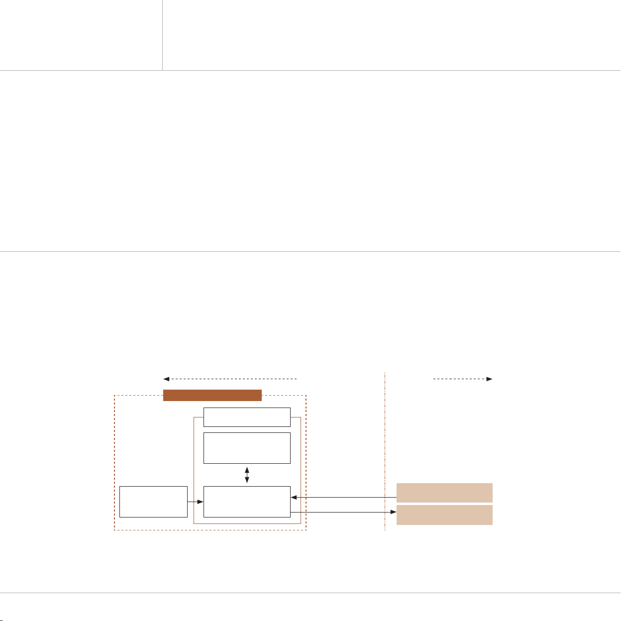
[Figure 1. GTD-2000Tx Overview]
Infrared Gas
Sensor Module
(GSA860TX)
Main Board
(Transmitter)
+24V DC
4-20mA Analog
Signal Output
Display Board
(User Interface)
Transmitter enclosure
Safety Power Supply Unit
(24VDC)
Safety Controller
(PLC or DCS)
GTD-2000Tx Gas Detector
Hazardous Area (Filed) Safe Area
GTD-2000Tx
Instruction Manual
3.1. Basic Specifications
ITEMS SPECIFICATION
Measuring Type Diffusion
Measuring Value Display LCD or OLED Display
Measuring Method
- Electro-Chemical Cell
- Heated-semiconductor Cell)
- Photoionization detector(PID)
Detectable Gas Toxic Gas (Note 1)
Measuring Range $BQBCMFUPEJTQMBZ_/PUF
Accuracy 'VMM3BOHF
Zero Drift 'VMM3BOHF
Response Time Depends on Sensor Module.
Refer to Sensor Specification or Contact in case for Special Gas.
Approvals Classification
KCs: Ex d llC T6,T5,T4, IP65
"5&9*&$&9**(&YE**$(C5_5
SIL2, MED, ABS, DNV
Basic Interface Analog 4-20mA current interface
HART Interface HART REV7 (Option)
Option
HART Board
(5-8BSOJOH-JHIU
Rain Cover
8BSSBOUZ Transmitter 2Year
Sensor 1Year
3.2. Mechanical Specifications
ITEMS SPECIFICATION
Explosion-Proof Type Explosion-Proof Enclosure
Dimension 8)%NN
8FJHIUJODMVEJOH4FOTPS App. 1.5kg
Mounting Type 8BMMNPVOU
Mounting Hole ʡ
Cable inlet 1'PS/15
Body Material Transmitter aluminum alloy
Sensor Stainless Steel (STS316)
GTD-2000Tx toxic gas detector has been developed to detect gas leaked from industrial sites and various toxic gases
generated from factories, gas storages, and manufacturing processes that produce or use toxic gases and to prevent
accidents in advance.
GTD-2000Tx toxic gas detector is installed in areas with gas leak hazards and continuously monitors gas leak. It displays
NFBTVSFNFOUTPOCVJMUJOEJTQMBZT-$%PS0-&%PGUIFEFUFDUPSBOEQSPWJEFT%$_N"TUBOEBSEPVUQVUTJHOBM"MTP
GPS%$_N"TUBOEBSEPVUQVUPVUQVUTJHOBMUSBOTNJTTJPOMFOHUICFUXFFOEFUFDUPSBOESFDFJWFSDBOCFDPOOFDUFEVQ
UPN8IFODBCMF$774PS$774#TRBOEIJHIFSJTVTFE(5%5YGMBNNBCMFHBTEFUFDUPSNVTUCFVTFE
at height below 1,000 m above sea level.
Body of GTD-2000Tx is made of Aluminum alloy and the gas sensor module is made of stainless steel. It consists of a
complete explosion-proof enclosure (Ex d IIC T6). This product can be installed in areas with combustible gas leak and
explosion hazards. It has built-in LCD on the detector to display gas leak status at installed site. It consists of display part
UIBUJOEJDBUFTNFBTVSFNFOUTUFSNJOBMQBSUUIBUPVUQVUNFBTVSFNFOUT%$_N"FYUFSOBMMZBOEB1$#CPBSE
External configuration consists of detector part that monitors gas leak and cable inlets. It uses magnet-bar outside the
main body of detector enabling calibration from the outside of the detector, thus, maintenance is convenient.
2. Structure
1. Overview 3. Specications
www.gastron.com
06_07
/PUF3FGFSUPUIFNFBTVSFEHBTMJTUGPSNFBTVSFEHBTFTBOEUIFJSSBOHFT$POUBDUVTGPSTQFDJBMHBT
[Figure 1. GTD-2000Tx Overview]
Infrared Gas
Sensor Module
(GSA860TX)
Main Board
(Transmitter)
+24V DC
4-20mA Analog
Signal Output
Display Board
(User Interface)
Transmitter enclosure
Safety Power Supply Unit
(24VDC)
Safety Controller
(PLC or DCS)
GTD-2000Tx Gas Detector
Hazardous Area (Filed) Safe Area
GTD-2000Tx
Instruction Manual
3.1. Basic Specifications
ITEMS SPECIFICATION
Measuring Type Diffusion
Measuring Value Display LCD or OLED Display
Measuring Method
- Electro-Chemical Cell
- Heated-semiconductor Cell)
- Photoionization detector(PID)
Detectable Gas Toxic Gas (Note 1)
Measuring Range $BQBCMFUPEJTQMBZ_/PUF
Accuracy 'VMM3BOHF
Zero Drift 'VMM3BOHF
Response Time Depends on Sensor Module.
Refer to Sensor Specification or Contact in case for Special Gas.
Approvals Classification
KCs: Ex d llC T6,T5,T4, IP65
"5&9*&$&9**(&YE**$(C5_5
SIL2, MED, ABS, DNV
Basic Interface Analog 4-20mA current interface
HART Interface HART REV7 (Option)
Option
HART Board
(5-8BSOJOH-JHIU
Rain Cover
8BSSBOUZ Transmitter 2Year
Sensor 1Year
3.2. Mechanical Specifications
ITEMS SPECIFICATION
Explosion-Proof Type Explosion-Proof Enclosure
Dimension 8)%NN
8FJHIUJODMVEJOH4FOTPS App. 1.5kg
Mounting Type 8BMMNPVOU
Mounting Hole ʡ
Cable inlet 1'PS/15
Body Material Transmitter aluminum alloy
Sensor Stainless Steel (STS316)
GTD-2000Tx toxic gas detector has been developed to detect gas leaked from industrial sites and various toxic gases
generated from factories, gas storages, and manufacturing processes that produce or use toxic gases and to prevent
accidents in advance.
GTD-2000Tx toxic gas detector is installed in areas with gas leak hazards and continuously monitors gas leak. It displays
NFBTVSFNFOUTPOCVJMUJOEJTQMBZT-$%PS0-&%PGUIFEFUFDUPSBOEQSPWJEFT%$_N"TUBOEBSEPVUQVUTJHOBM"MTP
GPS%$_N"TUBOEBSEPVUQVUPVUQVUTJHOBMUSBOTNJTTJPOMFOHUICFUXFFOEFUFDUPSBOESFDFJWFSDBOCFDPOOFDUFEVQ
UPN8IFODBCMF$774PS$774#TRBOEIJHIFSJTVTFE(5%5YGMBNNBCMFHBTEFUFDUPSNVTUCFVTFE
at height below 1,000 m above sea level.
Body of GTD-2000Tx is made of Aluminum alloy and the gas sensor module is made of stainless steel. It consists of a
complete explosion-proof enclosure (Ex d IIC T6). This product can be installed in areas with combustible gas leak and
explosion hazards. It has built-in LCD on the detector to display gas leak status at installed site. It consists of display part
UIBUJOEJDBUFTNFBTVSFNFOUTUFSNJOBMQBSUUIBUPVUQVUNFBTVSFNFOUT%$_N"FYUFSOBMMZBOEB1$#CPBSE
External configuration consists of detector part that monitors gas leak and cable inlets. It uses magnet-bar outside the
main body of detector enabling calibration from the outside of the detector, thus, maintenance is convenient.
2. Structure
1. Overview 3. Specications

www.gastron.com
08_09
3.3. Electrical Specifications (Standard Type)
ITEMS SPECIFICATION
Input Voltage(Standard)
$VTUPNFSTVQQMJFE146NVTUNFFU
requirements IEC1010-1 and CE
Marking requirements.
Absolute min:
Nominal:
Absolute max:
Ripple maximum allowed:
18V
24V
31V
1V pk-pk
8BUUBHF Max. wattage:
Max. current:
8!7%$
150mA @+24 VDC
Analog output Current
0-20mA(500 ohms max load)
"MMSFBEJOHTN"
Measured-value signal:
4mA(Zero) to 20mA(Full Scale)
Fault:
-&-
-&-
0WFS-&-
Maintenance:
0mA
4mA - 20mA
20mA - 21.4mA
22mA
3mA
Analog output current ripple & noise max V"
8JSJOHSFRVJSFNFOU Power CVVS or CVVSB with shield
Analog CVVS or CVVSB with shield
Signal Transmission Distance
(Cable Connection Length) Analog 2500m
EMC Protection: Complies with EN50270
No ITEMS SPECIFICATION
1Housing Body Protects PCB Board built in Sensor and Housing from external environmental change and shock.
2Housing Cover It is assembled with Detector Housing Body.
Top surface is built with circular glass to enable monitoring of measurement displayed on LCD.
3MAIN PCB Amplifies fine outputs generated from Sensor Element to transmit
BDPOWFSUFEPVUQVUJO_N"%$TUBOEBSE*UTFOETEBUBUPEJTQMBZQBSU
4Display PCB Displays data sent from MAIN/ Terminal (Transmitter) PCB on LCD and
displays power status with a power lamp.
5Power/Signal Terminal $/DPOTJTUTPG%$7QPXFSTVQQMZBOE%$_N"TUBOEBSEPVUQVU
connection terminal (VISO, +24V, mA, GND, ETH).
6Sensor Terminal CN8 is Sensor Connection Terminal.
7Power LED Lamp that turns on upon power supply.
8Function Key It is used to enter function setting mode from gas measuring mode by contacting magnet-bar for
2 sec or longer. It is also used to save changed data from function setting mode.
3.4. Environmental Specifications
ITEMS SPECIFICATION
Operation Temperature Transmitter UP
Sensor Refer to Sensor Specification
Storage Temperature Transmitter UP
Sensor Refer to Sensor Specification
Operation Humidity Transmitter UP3)/PODPOEFOTJOH
Sensor Refer to Sensor Specification
Pressure Range 90 to 110KPa
Max. air velocity 6m/s
[Figure 2. GTD-2000Tx Components]
GTD-2000Tx
Instruction Manual 3. Specications 4. Name and Description of Each Part
4.1. Components

www.gastron.com
10_11
No NAME DESCRIPTIONS
9Reset Key To cancel or return to the previous status during Parameter setting, use the Magnet-Bar and
touch once.
10 ¬61,FZ
(Each touch returns to the previous status by one unit.)
During conversion of mode or number, use the Magnet-Bar and touch once. Each touch converts
or increases displayed value by one unit.
11 %08/,FZ During conversion of mode or number, use the Magnet-Bar and touch once. Each touch converts
or increases displayed value by one unit.
12 External Earth Ground
It must be grounded to outside of detector for protection from external noise or strong electric
field.
- Use a conductor that is 4 mm or longer when coupling ground line.
13 Mount Hole Hole to fix the gas detector on external wall or other installation sites.
14 Sensor It is a site that detects actual gas leak. It converts the amount of gas leak into electrical signal and
transmits to the Main PCB.
15 Conduit Connection It is supplied for inlet of power supply and measurement output signal for the detector during
JOTUBMMBUJPO'PSDBCMFJOMFU1'PS/15BSFQSFQBSFE
16 Internal Ground
It must be grounded to inside of detector for protection from external noise or strong electric
field.
- Use a conductor that is 4 mm or longer when coupling ground line.
[Table 1. GTD-2000Tx Description of Configuration]
GTD-2000Tx
Instruction Manual 5. Installation
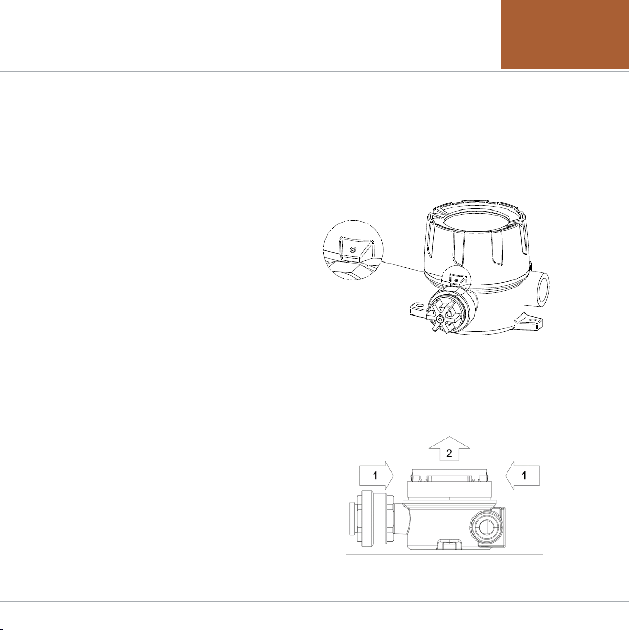
5.1. Detachment of Housing Cover
¥"GUFSEFUBDIJOHUIFDPWFSEJTBTTFNCMFUIFEJTQMBZQBSUT
as below.
˝ 1VTIJOMFGUBOESJHIUGJYJOHSJOHTMPDBUFEPOGSPOUTJEF
of LCD at the same time.
˞ 8IJMFQVTIJOHQVMMUIFEJTQMBZQBSUTUPXBSETUIFGSPOU
to detach from gas detector body.
˟ "GUFSEFUBDIJOHUIFEJTQMBZQBSUTUIF.BJO1$#JT
installed at the bottom part of the detector body.
It is prohibited for an individual, other than an approved user or a technician responsible for installation and repair from
the head office, to install a gas leak detector on site or open the cover of the installed gas leak detector and manipulate
it. This may cause serious loss of life and property from fire, explosion, and etc. In addition, please check whether there
is any remaining explosive gas or combustible material in the surroundings. Power must be turned off before performing
work.
¥8BSOJOH%POPUPQFOXIFOFMFDUJDBMDVSSFOUJT
flowing>
¥5VSOUIFTMPUUFETFUTDSFX.YFBGJYJOHUIFDPWFS
QBSUPGNBJOCPEZ_UVSOTDPVOUFSDMPDLXJTFDDX
using a hex wrench (M2) then turn the cover of gas
leak detector ccw to detach the cover.
8IFOUIFDPWFSJTEFUBDIFE-$%BQQFBST
[Figure 4. Display Part Detaching Method]
[Figure 3. Slotted Set Screw]
4. Name and Description of Each Part
www.gastron.com
10_11
No NAME DESCRIPTIONS
9Reset Key To cancel or return to the previous status during Parameter setting, use the Magnet-Bar and
touch once.
10 ¬61,FZ
(Each touch returns to the previous status by one unit.)
During conversion of mode or number, use the Magnet-Bar and touch once. Each touch converts
or increases displayed value by one unit.
11 %08/,FZ During conversion of mode or number, use the Magnet-Bar and touch once. Each touch converts
or increases displayed value by one unit.
12 External Earth Ground
It must be grounded to outside of detector for protection from external noise or strong electric
field.
- Use a conductor that is 4 mm or longer when coupling ground line.
13 Mount Hole Hole to fix the gas detector on external wall or other installation sites.
14 Sensor It is a site that detects actual gas leak. It converts the amount of gas leak into electrical signal and
transmits to the Main PCB.
15 Conduit Connection It is supplied for inlet of power supply and measurement output signal for the detector during
JOTUBMMBUJPO'PSDBCMFJOMFU1'PS/15BSFQSFQBSFE
16 Internal Ground
It must be grounded to inside of detector for protection from external noise or strong electric
field.
- Use a conductor that is 4 mm or longer when coupling ground line.
[Table 1. GTD-2000Tx Description of Configuration]
GTD-2000Tx
Instruction Manual 5. Installation
5.1. Detachment of Housing Cover
¥"GUFSEFUBDIJOHUIFDPWFSEJTBTTFNCMFUIFEJTQMBZQBSUT
as below.
˝ 1VTIJOMFGUBOESJHIUGJYJOHSJOHTMPDBUFEPOGSPOUTJEF
of LCD at the same time.
˞ 8IJMFQVTIJOHQVMMUIFEJTQMBZQBSUTUPXBSETUIFGSPOU
to detach from gas detector body.
˟ "GUFSEFUBDIJOHUIFEJTQMBZQBSUTUIF.BJO1$#JT
installed at the bottom part of the detector body.
It is prohibited for an individual, other than an approved user or a technician responsible for installation and repair from
the head office, to install a gas leak detector on site or open the cover of the installed gas leak detector and manipulate
it. This may cause serious loss of life and property from fire, explosion, and etc. In addition, please check whether there
is any remaining explosive gas or combustible material in the surroundings. Power must be turned off before performing
work.
¥8BSOJOH%POPUPQFOXIFOFMFDUJDBMDVSSFOUJT
flowing>
¥5VSOUIFTMPUUFETFUTDSFX.YFBGJYJOHUIFDPWFS
QBSUPGNBJOCPEZ_UVSOTDPVOUFSDMPDLXJTFDDX
using a hex wrench (M2) then turn the cover of gas
leak detector ccw to detach the cover.
8IFOUIFDPWFSJTEFUBDIFE-$%BQQFBST
[Figure 4. Display Part Detaching Method]
[Figure 3. Slotted Set Screw]
4. Name and Description of Each Part

www.gastron.com
12_13
5. Installation5. Installation
GTD-2000Tx
Instruction Manual
5.2. Main PCB Configuration
¥"GUFSEFUBDIJOHUIFDPWFSUIF.BJO1$#UFSNJOBMMBZPVUBQQFBSTBTTIPXOJOUIFGJHVSFCFMPX
[Table 2. Main PCB Key Part Description]
No NAME DESCRIPTION
1CN9 Power & Output Signal Terminal
2J1 _N"4PVSDF4JOL4FMFDUJPO+VNQFS0/4PVSDF5ZQF0''4JOL5ZQF
3CN1 Display LCD Connector
4CN8 Sensor Connector
5CN6 Program download Connector
6D1 Status LED (Flashes in 1 sec interval during normal operation)
7OC1,OC2,OC3 HART Option Board Connector
8CN4 8BSOJOHMJHIU(5-*OUFSGBDF$POOFDUPS
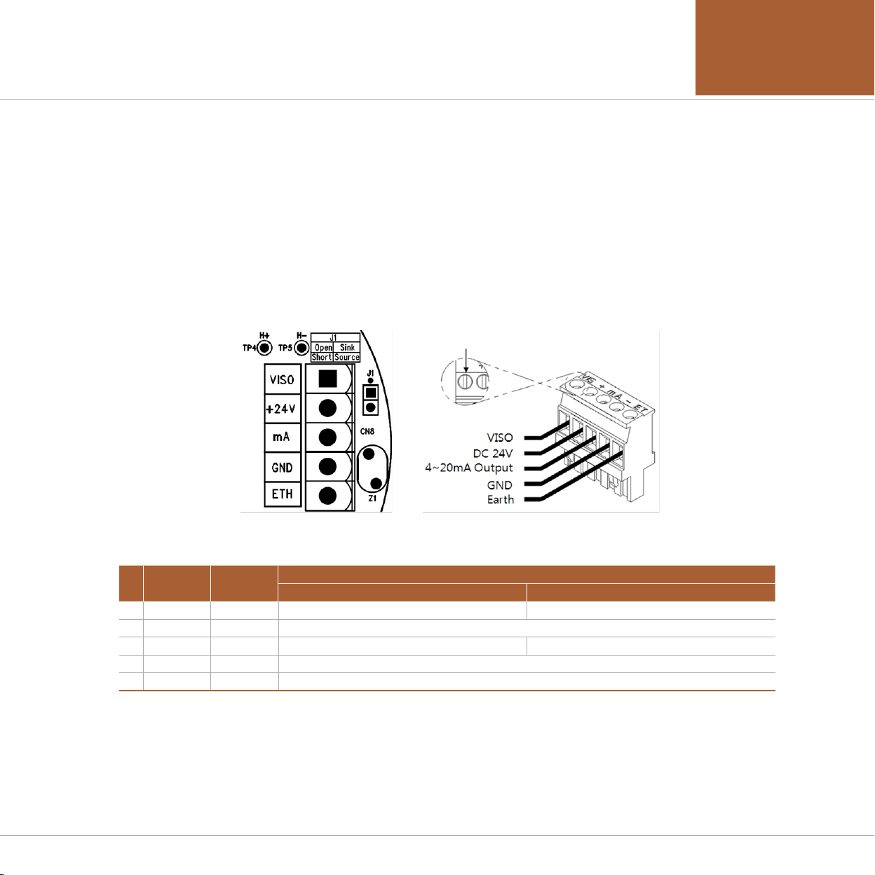
[Figure 5. Main PCB Terminal Layout]
5.3. Terminal Configuration
¥8BSOJOH5VSOPGGQPXFSCFGPSFDPOOFDUJOHQPXFSUFSNJOBM
¥"GUFSEJTBTTFNCMJOHEJTQMBZQBSUTUIFSFJTBUFSNJOBMCMPDLJOUIF.BJO1$#BTTIPXOJOUIFGJHVSFCFMPX
Holding it with hands and pulling towards ceiling detaches it from the Main PCB.
¥-PPTFOUFSNJOBMGJYJOHTDSFXTMPDBUFEBUUPQQBSUPGEFUBDIFEUFSNJOBMCMPDL$/7*4N"&5)$POOFDUPSCZ
UVSOJOHDDXVTJOHBǞESJWFS$POOFDU%$_7QPXFSUPBOEUIFODPOOFDUTJHOBMDBCMFUPN"5JHIUFOUFSNJOBM
fixing screws clockwise (cw) so that terminal does not leave the track then insert Main PCB as the same condition
before disassembly.
¥6TJOH0$0$BOE0$TIPXOJOUIFMBZPVUBCPWF)"35PQUJPOCPBSEDBOCFBUUBDIFEBOEʡ4DSFXIPMFT
located at top left of HART option board are used for fixing.
[Figure 6. CN9 Terminal Configuration]
[Table 3. CN9 Terminal Detailed Description]
NO PCB SILK PIN NAME DESCRIPTION
4~20mA Source Drive (J1 Jumper ON) 4~20mA Sink Drive (J1 Jumper OFF)
1VISO VIS N.C _N"4JOL*O
2+24V +7108&3
3mA mA _N"4PVSDF0VU _N"4JOL0VU
4GND -(/%108&3
5ETH ET EARTH
¥6TF$774PS$774#TR¬4IJFME$BCMFGPSUFSNJOBMDPOGJHVSBUJPO
¥ 5PDPOOFDU1JOUFSNJOBMGSPNUIFFYJTUJOHPME(5%5YNPEFMDPOOFDUUFSNJOBMTJOSFGFSFODFUPQJO
which is +24V.
Terminal mounting screw
www.gastron.com
12_13
5. Installation5. Installation
GTD-2000Tx
Instruction Manual
5.2. Main PCB Configuration
¥"GUFSEFUBDIJOHUIFDPWFSUIF.BJO1$#UFSNJOBMMBZPVUBQQFBSTBTTIPXOJOUIFGJHVSFCFMPX
[Table 2. Main PCB Key Part Description]
No NAME DESCRIPTION
1CN9 Power & Output Signal Terminal
2J1 _N"4PVSDF4JOL4FMFDUJPO+VNQFS0/4PVSDF5ZQF0''4JOL5ZQF
3CN1 Display LCD Connector
4CN8 Sensor Connector
5CN6 Program download Connector
6D1 Status LED (Flashes in 1 sec interval during normal operation)
7OC1,OC2,OC3 HART Option Board Connector
8CN4 8BSOJOHMJHIU(5-*OUFSGBDF$POOFDUPS
[Figure 5. Main PCB Terminal Layout]
5.3. Terminal Configuration
¥8BSOJOH5VSOPGGQPXFSCFGPSFDPOOFDUJOHQPXFSUFSNJOBM
¥"GUFSEJTBTTFNCMJOHEJTQMBZQBSUTUIFSFJTBUFSNJOBMCMPDLJOUIF.BJO1$#BTTIPXOJOUIFGJHVSFCFMPX
Holding it with hands and pulling towards ceiling detaches it from the Main PCB.
¥-PPTFOUFSNJOBMGJYJOHTDSFXTMPDBUFEBUUPQQBSUPGEFUBDIFEUFSNJOBMCMPDL$/7*4N"&5)$POOFDUPSCZ
UVSOJOHDDXVTJOHBǞESJWFS$POOFDU%$_7QPXFSUPBOEUIFODPOOFDUTJHOBMDBCMFUPN"5JHIUFOUFSNJOBM
fixing screws clockwise (cw) so that terminal does not leave the track then insert Main PCB as the same condition
before disassembly.
¥6TJOH0$0$BOE0$TIPXOJOUIFMBZPVUBCPWF)"35PQUJPOCPBSEDBOCFBUUBDIFEBOEʡ4DSFXIPMFT
located at top left of HART option board are used for fixing.
[Figure 6. CN9 Terminal Configuration]
[Table 3. CN9 Terminal Detailed Description]
NO PCB SILK PIN NAME DESCRIPTION
4~20mA Source Drive (J1 Jumper ON) 4~20mA Sink Drive (J1 Jumper OFF)
1VISO VIS N.C _N"4JOL*O
2+24V +7108&3
3mA mA _N"4PVSDF0VU _N"4JOL0VU
4GND -(/%108&3
5ETH ET EARTH
¥6TF$774PS$774#TR¬4IJFME$BCMFGPSUFSNJOBMDPOGJHVSBUJPO
¥ 5PDPOOFDU1JOUFSNJOBMGSPNUIFFYJTUJOHPME(5%5YNPEFMDPOOFDUUFSNJOBMTJOSFGFSFODFUPQJO
which is +24V.
Terminal mounting screw

www.gastron.com
14_15
5. Installation5. Installation
GTD-2000Tx
Instruction Manual
5.3.1. Wiring for 4~20mA Source Operation Type 5.3.3. Wiring for 4~20mA 3Wire Sink Operation Type
5.3.2. Wiring for 4~20mA Sink Operation Type
[Figure 7. 4-20mA Source Configuration]
[Figure 8. 4-20mA Sink Configuration]
¥$POOFDUN"TJHOBMUFSNJOBMBU1-$TJEFUPN"PG
GTD-2000Tx. GND terminal is used in common with
power.
Then, turn on the J1 jumper.
¥)"35$PNNVOJDBUPSDBOPOMZCFVTFEJONPEFMTVTJOH
HART Option board.
¥$POOFDUBOEUFSNJOBMTGPSN"TJOLPVUQVU
at PLC side to VISO terminal and power (24V DC) (-)
UFSNJOBMSFTQFDUJWFMZ$POOFDUN"UFSNJOBMPG(5%
5YUP(/%UFSNJOBM5IFOUVSOPGGUIF+KVNQFS
¥$POOFDUBOEUFSNJOBMTGPSN"TJOL
PVUQVUBU1-$TJEFUP7*40UFSNJOBMBOEN"UFSNJOBM
respectively. Then, turn off the J1 jumper.
¥)"35$PNNVOJDBUPSDBOPOMZCFVTFEJONPEFMTVTJOH
HART Option board.
<'JHVSFN"8JSF4JOL$POGJHVSBUJPO>
5.4. Installation Cable Length
¥5IFNBYJNVNMFOHUICFUXFFO(5%5YBOEQPXFSTVQQMZJTEFDJEFECZXJSFTQFDJGJDBUJPO
¥.BY*OTUBMMBUJPO-FOHUI7."9%301*."98*3&3N
h7."9%301.BYJNVN1PXFS-PPQ7PMUBHF%SPQ1PXFS4VQQMZWPMUBHF
- min operating voltage)
·IMAX : Max. Current of GTD-2000Tx
h8*3&3N5IFSFTJTUBODFPGUIFXJSFPINTNFUFSWBMVFBWBJMBCMFJOXJSFNBOVGBDUVSFSTTQFDJGJDBUJPOEBUBTIFFU
¥&YBNQMFPGJOTUBMMBUJPOMFOHUITVTJOH7QPXFSTVQQMZBOE"8(JTBTGPMMPXT
h(5%5YNJOJNVNPQFSBUJOHWPMUBHF7ED
h7."9%3017
h*."9"N"
hNN

www.gastron.com
16_17
GTD-2000Tx
Instruction Manual 5. Installation
¥1PXFSDBCMFJOTUBMMBUJPOGPSFBDIDBCMFUZQFJTBTTIPXOJOUIFUBCMFCFMPX
AWG mm2 COPPER RESISTANCE(ohms/m) METERS
12 3.31 0.00521 3838
14 2.08 0.00828 2415
16 1.31 0.01318 1517
18 0.82 0.02095 954
20 0.518 0.0333 600
[Figure 10. Calculation of GTD-2000Tx Installation Cable Length]
[Table 4. GTD- 2000Tx Power Cable Installation Length]
6.1. Initial Operation Status (Power On)
¥"GUFSXJSJOHUPQPXFSUFSNJOBMBUUIFUPQPG.BJO1$#CPBSEUIFOTVQQMZQPXFSUIFGPMMPXJOHDPOUFOUTBSFEJTQMBZFE
on LCD. Approx. 30 m of stabilization of time is needed from the initial supply of operation power and it starts to
operate normally after sufficient stabilization.
GTD-2000
[V X.XX] 8IFOQPXFSUVSOTPONPEFMOBNFBOEQSPEVDUGJSNXBSFWFSTJPOBSFEJTQMBZFEPO-$%0-&%
SELF TEST
[ >>>0179] 4FMGUFTUJTQFSGPSNFEGPSNJONJOGPS0TFUVQTZNCPMJOUIFTFDPOESPXTIPXTUIFQSPHSFTT
[ %LEL]
[ 0.0]
- In normal operation mode, it runs as below.
- In the first row, measured gas name and unit are displayed in 1 sec interval. In the second row, the
- current measurement is displayed.
*OUIFDVSSFOUTDSFFOUPVDIJOHUIFNBHOFUCBSPO'VODLFZGPSTFDPSMPOHFSDIBOHFTUPTFUUJOHNPEF
- %VSJOH.PECVTOFUXPSLJTEJTQMBZFEPOUIFMFGUPGUIFGJSTUSPX
- &/(8IFOUIFNPEFJTPOJTEJTQMBZFEPOUIFMFGUPGUIFTFDPOESPX
[ COMB.]
[ 0.0]
[ %LEL]
[ 30]
8IFOBMBSNPSPDDVSTJUSVOTBTCFMPX*UPOMZSVOTPOMZXIFOBMBSNVTFETFUUJOHJOBMBSNNPEFJTPO
- The first row runs the same as in normal status. In the second row, alarm message and gas
- measurement are displayed in 1 sec interval.
8IFO(5-FYQMPTJPOQSPPGXBSOJOHMJHIUJTJOTUBMMFEVQPOBOFWFOUPGBMBSNSFE-&%BOECV[[FS
- flicker and run in 1 sec interval. Upon an event of alarm2, they continuously run without flickering.
- If alarm latch is on, the alarm continuously run until it is released using the reset key.
[ %LEL]
[ ALARM1 ]
[ %LEL]
[ OVER ]
8IFOHBTNFBTVSFNFOUMBSHFSUIBOPGTFUIJHITDBMFWBMVF07&3EJTQMBZTJOTFDJOUFSWBM
- "UUIJTUJNF_N"SVOTBTN"
[ %LEL]
[ UNDER ]
8IFOHBTNFBTVSFNFOUTNBMMFSUIBO6/%&3EJTQMBZTJOTFDJOUFSWBMBOE_N"SVOT
- below 2 mA.
- 5IFGPMMPXJOHGVODUJPOPOMZSVOTXIFO6/%&3JTPO
[FAULT1]
SEN HUNT
8IFOUSPVCMFPDDVSTJOUIFEFWJDFJUEJTQMBZTGBVMUOVNCFSBOENFTTBHF
"UUIJTUJNF_N"SVOTCFMPXN"
*UJTBNPEFUIBUEJTQMBZTXIFO'BVMUTFOTPSPOUIFMFGUJTOPUFRVJQQFE
6.2. Measuring Mode
¥"GUFSQPXFSPOXIFOUIFSFJTOPFSSPSGSPN4&-'5&45JUBVUPNBUJDBMMZFOUFST.FBTVSJOH.PEF
6. Detector Operation Flow
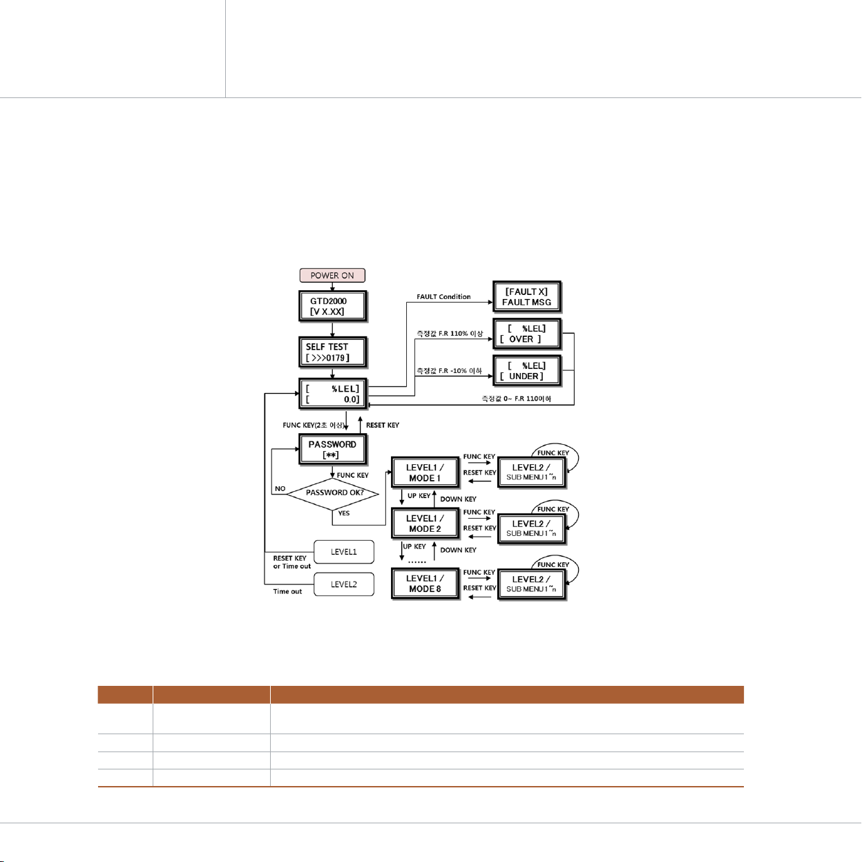
www.gastron.com
18_19
GTD-2000Tx
Instruction Manual
6.3. Operation Flow 6.4. Menu Configuration Table
¥"GUFSQPXFSPOJUQBTTFTTFMGEJBHOPTUJDQSPDFTTUIFOFOUFST.FBTVSJOH.PEF)FSFCZPQFSBUJOHGSPOULFZTZPV
can go to internal System Mode.
¥5JNFPVUGPS-FWFMBOE-FWFMBSFTFD*UJTTFUUPIPVSGPS-FWFM$BMJCSBUJPOBOE5FTU.PEF
¥8IFO3&4&5LFZDPOUBDUTBU1SPHSBN.PEF4DSFFOJUSFUVSOTUP.FBTVSJOH.PEF8IFO3&4&5LFZDPOUBDUT
at each Program Setting Screen, it returns to the parent step.
¥0QFSBUJPOLFZTGPSEFUFDUPSTZTUFNNPEFBSFEFGJOFEBTCFMPX
[Figure 11. GTD-2000Tx Mode Configuration]
ITEM NAME DESCRIPTION
FUNC Function key Detector Mode Setting Entry Function (Insert Magnetic-bar for 2 sec or longer in measuring mode)
Level2 Next stage entering function and setting saving function
RESET Reset key Move to the previous stage from the level entered.
¬Up key Next level mode that is configured in LEVEL1 and Change in Level2 setting Plus
Down key Next level mode that is configured in LEVEL1 and Change in Level2 setting Minus
LEVEL1 LEVEL2 DEFAULT
NAME PARAMETER
PROGRAM
MODE
GAS TYPE (Gas Type) [DEFIN./USER] DEFIN.
GAS SEL(Gas Select) Built-in gas name selection COMB.
UNIT SEL (Unit Select) -&-11.11# -&-
D-POINT(Decimal Point) 0.100/1.00/10.0/100 100
HIGH SCL (High Scale) _ 100
1"44803%_ 00
CALIBRA.
MODE
(Calibration Mode)
CALIBRA.
[ZERO]
(Calibration Zero)
ZERO CAL
[NO,YES] [NO]
ZERO GAS
[ 0]
ZERO >>>>
[SUCCESS / FAIL]
CAL. DATA
[ 0/ FAIL]
CALIBRA.
[SPAN]
(Calibration Span)
SPAN CAL
[NO , YES] [NO]
SPAN GAS
[ 0]
SPAN SET
[ 50/ FAIL] 50
SPAN >>>>
[SUCCESS / FAIL ]
CAL. DATA
[ 0]
ALARM
MODE
ALM USED (Alarm Used) [OFF / ON] OFF
AL LATCH (Alarm Latch) [OFF / ON] OFF
A1 LEVEL (Alarm-1 Level) <_> 20
A1 TYPE(Alarm-1 Type) [INC / DEC] INC
A1 DBAND (Alarm-1 Dead Band) <_'4> 0
A1 TIME (Alarm-1 Time) <_>4&$ 1
A2 LEVEL (Alarm-2 Level) <_> 20
A2 TYPE(Alarm-2 Type) [INC / DEC] INC
A2 DBAND (Alarm-2 Dead Band) <_'4> 0
A2 TIME (Alarm-2 Time) <_>4&$ 1
SENSOR MODE Factory Setting
MAINTEN.MODE Factory Setting
DEVICE MODE Factory Setting
VERSION MODE Factory Setting
TEST MODE Factory Setting
6. Detector Operation Flow 6. Detector Operation Flow

www.gastron.com
20_21
GTD-2000Tx
Instruction Manual
7.1. PROGRAM MODE
PASSWORD
[**]
$POUBDUJOH'6/$LFZXJUIUIF.BHOFUCBSGPSTFDPSMPOHFSJO.FBTVSJOH.PEFFOUFST1BTTXPSENPEF
"GUFSTFUUJOH1BTTXPSEVTJOH¬PSLFZDPOUBDU'6/$LFZ
PROGRAM
MODE
- If password is correct, it enters Program mode.
#ZDPOUBDUJOH¬uPSuLFZNPEFDIBOHFTJOEFGJOFEPSEFS
- ( PROGRAM -> CALIABRA. -> ALARM -> SENSOR -> MAINTEN. ->DEVICE -> VERSION -> TEST )
GAS TYPE
[ DEFIN. ]
.PEFUIBUTFUTHBTOBNFUZQFBOEDPOUBDUJOH¬PSLFZDIBOHFTHBTUZQF%&'*/64&3
- DEFIN. Is acronym for Define and is selected when using built-in setting of gas name.
- USER is selected when the user directly sets a gas name.
8IFOBEFTJSFEHBTUZQFJTEJTQMBZFEDPOUBDU'6/$LFZUPTFUUIFHBTOBNFBOEFOUFS1SPHSBN.PEF
GAS SEL
[ COMB. ]
.PEFUIBUTFUTHBTOBNFBOEDPOUBDUJOH¬PSLFZDIBOHFTHBTOBNF
8IFOHBTUZQFJTTFUUP%&'*/CVJMUJOHBTOBNFTDBOCFTFMFDUFEGPSVTF8IFOJUJTTFUUP64&3
- the user shall set gas name using 5 character for use. Characters allowed for use are number, capital
- "MQIBCFUTQBDFBOEQFSJPE8IFOQPTJUJPOJTNPWFECZTFUUJOHDIBSBDUFSTBDVSTPSJOCMBDLCPYTIBQF
- appears as shown in the figure on left.
USER GAS
<¥>
UNIT SEL
[ %LEL ]
.PEFUIBUTFUTHBTNFBTVSJOHVOJUBOEDPOUBDUJOH¬PSLFZDIBOHFTHBTNFBTVSJOHVOJU
- -&-11.11#
8IFOBEFTJSFEHBTNFBTVSJOHVOJUJTEJTQMBZFEDPOUBDU'6/$LFZUPTFUUIFVOJUBOEFOUFS1SPHSBN
- Mode.
D-POINT
[ 100]
.PEFUIBUDIBOHFTEFDJNBMQMBDFBOEDPOUBDUJOH¬PSLFZDIBOHFTEFDJNBMQMBDF
- (0.100/1.00/10.0/100)
8IFOBEFTJSFEEFDJNBMQMBDFJTEJTQMBZFEDPOUBDU'6/$LFZUPTFUUIFEFDJNBMQMBDFBOEFOUFSUIF
- next Program Mode.
HIGH SCL
[ 100]
.PEFUIBUTFUTIJHITDBMFWBMVFUIBUTIPVMECFEJTQMBZFEGPSGVMMSBOHF$POUBDUJOH¬PSLFZ
- JODSFBTFTPSEFDSFBTFTUIFTDBMFWBMVF_
8IFOBEFTJSFEIJHITDBMFJTEJTQMBZFEDPOUBDU'6/$LFZUPTFUUIFIJHITDBMFWBMVFBOEFOUFSUIF
- next Program Mode.
PASSWORD
[00]
- It is password setting mode. This password is checked when entering Program Mode.
4FUVTJOH¬PSLFZUIFODPOUBDU'6/$LFZUPTFUUIFQBTTXPSEBOEFOUFSUIFOFYU1SPHSBN.PEF
7. System Mode7. System Mode
7.2. CALIBRATION MODE
7.2.1. Zero Calibration
PASSWORD
[**]
$POUBDUJOH'6/$LFZXJUIUIF.BHOFUCBSGPSTPSMPOHFSJO.FBTVSJOH.PEFFOUFST1BTTXPSE
- mode.
"GUFSTFUUJOH1BTTXPSEVTJOH¬PSLFZDPOUBDU'6/$LFZ
CALIBRA.
MODE
$POUBDU¬PSLFZUPTFMFDU$BMJCSBUJPO.PEF
$POUBDU'6/$LFZXIFO$"-*#3".0%&JTEJTQMBZFEUPFOUFS$BMJCSBUJPO.PEF
$POUBDU3&4&5LFZUPSFUVSOUP.FBTVSJOH.PEF
CALIBRA.
[ZERO]
8IFO$"-*#3"5*0/.0%&JTEJTQMBZFEDPOUBDUJOH'6/$LFZTFMFDUT;FSP$BMJCSBUJPO
$POUBDU¬PSLFZUPBDIJFWF<;&30>UIFODPOUBDU'6/$LFZUPFOUFS;FSP$BMJCSBUJPO
ZERO CAL
[ NO] $POUBDU¬PSLFZUPBDIJFWF<:&4>UIFODPOUBDU'6/$LFZUPQFSGPSN;FSP$BMJCSBUJPO
ZERO GAS
[ 0]
6TJOHBDBMJCSBUJPOUPPMJOKFDUDMFBOBJSPSOJUSPHFOJOUPUIFTFOTPSBUBGMPXSBUFPGN-NJO
- GPSNJO$POUBDU'6/$LFZXIFONFBTVSFNFOUJTTUBCJMJ[FEUPBVUPNBUJDBMMZQFSGPSN;FSP$BMJCSBUJPO
ZERO >>
[SUCESS]
8IFO[FSPDBMJCSBUJPOJTTVDDFTTGVM;&3046$$&44JTEJTQMBZFEGPSTFDPO-$%EJTQMBZUIFOJU
- DIBOHFTUP$"-*#3"5*0/%"5".PEF
8IFO[FSPDBMJCSBUJPOJTOPUTVDDFTTGVM;&30'"*-JTEJTQMBZFEGPSTFDBOEJUDIBOHFTUP
- $BMJCSBUJPO%BUB.PEF
;&30'"*-PDDVSTXIFOTFOTPSJOQVUWBMVFFYDFFETPGUPUBM"%$JOQVUSBOHF
ZERO >>
[ FAIL ]
CAL.DATA
[ 0]
- It is a mode to display measurement after calibration and checks whether calibration is successful after
- performing auto calibration.
8IFOJUGBJMFEJUEJTQMBZT'"*-BOEUIFDVSSFOUNFBTVSFNFOUJOTFDJOUFSWBM
$POUBDU3&4&5LFZUPSFUVSOUP$BMJCSBUJPONPEF
¥%VFUPDIBSBDUFSJTUJDTPGUIFHBTEFUFDUPSNJOJNVNNJOPGTUBCJMJ[BUJPOUJNFJTSFRVJSFEBOENBJOUFOBODF
condition may change depending on site condition.
Table of contents
Other Gas Detection Gas Detector manuals


Popular Gas Detector manuals by other brands


EsiWelma
EsiWelma Sensigas ESN I Series quick start guide

Crowcon
Crowcon Gas-Pro User & Operator Manual

Osaka
Osaka DG-3R instructions

Evikon
Evikon PluraSens E2608-LEL user manual

Perry Electric
Perry Electric 1GA50917MET/P Installation and operating instructions

Taichuan
Taichuan TC-U9AF-CO/Z installation instructions


