EsiWelma Sensigas ESN I Series User manual

EsiWelma s.r.l.
rev. 02 of 01-09-10 / pg. 1
E223.302
LPG and Methane gas detectors
for homes, recreational vehicles and similar sites
Conformity standard CEI 216-8
ESN.I.P..
for LPG
ESN.I.G..
for Methane gas
___________________________________________________________________________________________
LPG and Methane gas detectors for homes, recreational vehicles and similar sites.
230Vac, 12Vac/dc or 12…24Vac/dc power supply, depending on the model.
Relay command output with double insulation voltage free contact, so suitable for any kind of solenoid
valve or other command and alarm device.
Possibility of parallel connection of more than one detector, also for monitoring different gases.
___________________________________________________________________________________________
Use
The ESN.I.P/.G detectors can be used to provide a visual/audible alarm and to control a gas
shut-off valve (and to control other alarm transmitters or actuating devices), where there are
abnormal concentrations well below the LPG or Methane gas hazard threshold.
___________________________________________________________________________________________
Operation
The detector will enter a warm-up phase after power-up; this will take about 60" and during
this time the detector is inoperative. At the end of the warm-up phase, the detector enters
normal operation mode, and will continue in this state until it detects gas.
Gas detection
In this case, so when the gas concentration exceeds the threshold set-points, the detector
senses its presence and goes into the alarm condition indicated by the red LED coming on
and by the sound of the integrated buzzer. After about 20s, the internal relay is switched to
transmit a command to shut off the solenoid valve and any other shut-off or alarm devices.
Once the alarm condition is normalised, the detector is restored to its normal operating status.
Depending on the type of system constructed, it may be necessary to manually reset the
solenoid valve to restore gas flow at the dedicated reset device.
___________________________________________________________________________________________
Power supply
Detector
230Vac
12Vac/dc
12…24Vac/dc
Recessed ESN.I.P/.G.x ESN.I.P/.G.x.D ESN.I.P/.G.x.E
Wall-mounted ESN.I.P/.G.x + ESN.KW ESN.I.P/.G.x.D + ESN.KW ESN.I.P/.G.x.E + ESN.KW
Table-top ESN.I.P/.G.x + ESN.KT ESN.I.P/.G.x.D + ESN.KT ESN.I.P/.G.x.E + ESN.KT
Table-top (precabled)
ESN.I.P/.G.x + ESN.KC ESN.I.P/.G.x.D + ESN.KC ESN.I.P/.G.x.E + ESN.KC
The letter A or B inserted in field xof the product order number indicates the type of detector, i.e.:
A= with relay command output B= without relay command output (visual/audible alarm)
___________________________________________________________________________________________
Available
models
and ordering
information

EsiWelma s.r.l.
rev. 02 of 01-09-10 / pg. 2
_______________________________________________________________________________________
Outputs
Detector status
LED
GREEN
LED
YELLOW
LED
RED
BUZZER RELAY
Off OFF OFF OFF OFF OFF
Sensor warm-up (60 seconds) ON ON OFF OFF OFF
Normal operation ON OFF OFF OFF OFF
Sensor fail ON ON OFF OFF OFF
Alarm ON OFF ON ON ON
Operational test like in alarm, for the time the button is pressed down
Key:
ON = steady on / activated / switched OFF = off / deactivated / not switched
___________________________________________________________________________________________
Ensure compliance with standards in force for electrical wiring. The devices must be connected to the mains
and remain permanently powered. Omnipolar disconnection must be included in the mains.
Carefully read the instructions and electrical wiring diagrams in this document and follow them to the letter.
Keep this document in a safe place for future consultation.
The device must be installed by qualified technicians.
Installation
The detector must be installed:
Methane Gas: since this gas is lighter than air, it will be con-
centrated close to the ceiling. Install it about two metres from
the gas device and about 30 cm from the ceiling.
For LPG (liquid gas in cylinders): since this gas is heavier
than air, it will be concentrated close to the floor. Install it about
two metres from the gas device and about 30 cm from the floor.
The detector must not be installed:
• outdoors
• near stoves and cooking appliances
• near sinks and taps
• near exhaust hoods, windows, fans etc.
• in areas where dirt and/or dust can clog the front grille of
the detector
• where the temperature or humidity exceeds the detector's
operating limits
• in closed spaces (behind curtains, inside cupboards etc.).
depending on the model purchased, the detector can be mounted:
1. directly in type 503 recessed mounting box
2. screwed onto the wall with adapter ESN.KW
3. on a shelf in the table-top version, using adapter ESN.KT/KC.
Before fixing the detector to box 503 or to adapter ESN.KW or ESN.KT/KC, the bracket needs to be adjusted to
the backing plate selected from major manufacturers of recessing equipment (see Table 1) and, if necessary,
two side adapters need to be inserted to cover the side gap created when using some plates.
Table 1
Manufacturer: Side
adapters Tabs to
remove
AVE
SISTEMA 45 and BANQUISE YES None
BTICINO
Living international and Light NO A
GEWISS
PLAYBUS and PLAYBUS Young YES A
SIEMENS
DELTA FUTURA GRAPHIT YES A
VIMAR
IDEA and RONDO’ YES B
___________________________________________________________________________________________
Operational
table
Installation and
Commissioning
ESN.I.G
ESN.I.P

EsiWelma s.r.l.
rev. 02 of 01-09-10 / pg. 3
___________________________________________________________________________________________
Commissioning
Power up the detector and check that all the warm-up and normal operation phases are executed.
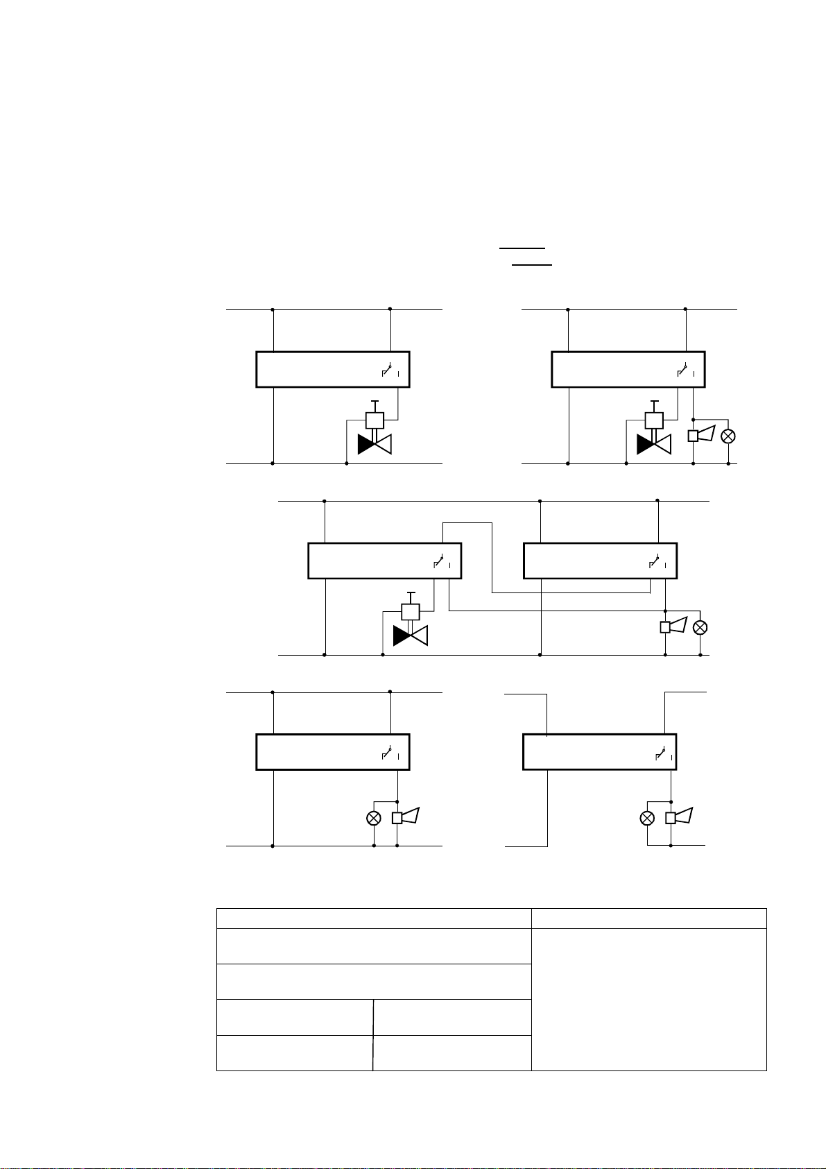
Carry out an operational response test by pressing the button on the front (or use a dedicated LPG calibration
canister with dosing valve and release a small amount of gas near the front grille) to check the correct
engagement of the solenoid valve and other command and/or alarm device connected to the relay; it is
advisable to repeat the operational test at least once a year, or after a prolonged period of stoppage.
If other test methods are used instead of the one described the detector may generate different, unexpected
responses. In particular, the use of inappropriate substances or vapours (alcohol or silicon-based solvents etc.)
or in any case, high concentrations of test gases could cause permanent damage to the sensing element and
may cause the detector to operate incorrectly.
The detector needs no periodic maintenance, with the exception of the periodic operational test and its re-
placement 5 years after the installation date.
Do not tamper with or open the device: danger of electric shock and/or malfunction.
Use a wet cloth and mild detergent to periodically clean the device.
Do not use aggressive detergents like alcohol, ammonia, solvents etc.
Before cleaning the detector, switch off the system power supply to avoid the risk of electric shock.
Warning
The detector and its sensing element have been designed for ongoing use in areas where there is permanent
occupation by people, so normally pollution-free.
The presence of gases or vapours from some substances such as alcohol, silicons or solvents found in some
detergents or polishes, or from the fumes generated by cooking may cause inappropriate action of the detector
and in the long term could affect the reliability of the device.
The particular Methane and LPG odorization made by the distributor, together with the high sensitivity of the
human olfactory apparatus, make it possible to smell the presence of these gases already at extremely low
concentrations, so a lot earlier than the detector. For operational and regulatory reasons, the detector is
calibrated to take action at a higher threshold which is still very far below the hazard threshold.
___________________________________________________________________________________________
If an alarm goes off, stay calm, put out flames, switch off the gas or LPG cylinder at the meter, do not switch on
or off lights or any electrical appliances or equipment, open doors and windows to increase the flow of fresh air.
If the alarm stops, it is necessary to find out what set it off and take consequent action.
If the alarm continues and the reason for the presence of gas cannot be determined or eliminated, leave the
building and contact emergency services.
___________________________________________________________________________________________
(1) LEL = Lower Explosive Limit
___________________________________________________________________________________________
In the event
of alarm
Technical
specifications
Power supply (see available models) 230Vac
±
10% or 12Vac/dc
±
10% or 12…24Vac/dc
Frequency 50/60Hz
Consumption 2 VA
Command outputs SPDT relay - capacity of the contact 250Vac 5(3)A
Alarm threshold 9% of L.E.L
(1)
of the Methane or LPG, depending on the
model
Operational lifetime of a detector 5 years from installation
Max detectable area approx. 40 m
2
Visual warnings Green LED (power is on)
Yellow LED (warm-up / sensor fail)
Red LED (gas alarm)
Audible alarms:
Piezoelectric buzzer 85dB at 1m
Protection Rating IP42 when correctly installed
Product conformity standard
EMC Electromagnetic Compatibility
Low voltage (LVD)
CEI216-8
EMC 2004/108/EC – EN50270
LV 2006/95/EC – EN60669-1
Operational room temperature -10...+40 °C
Ambient humidity allowed: 30...90% RH (non condensing)
Dimensions For installation in 503 type recessed mounting box
• 142 x 100 x 72mm with ESN.KW wall-mounting adapter
• 142 x 120 x 100mm with ESN.KT/KC table-top adapter
Enclosure ABS/PC UL94-V0 flame retardant

EsiWelma s.r.l.
rev. 02 of 01-09-10 / pg. 4
___________________________________________________________________________________________
Wiring diagrams:
Example a): - Command of a solenoid valve (Normally Open); in this mode, when the alarm threshold is ex-
ceeded the solenoid valve will close and therefore the gas supply will be cut-off.
Example b): - Command of a solenoid valve (Normally Closed); in this mode, the solenoid valve will close and
therefore the gas supply will be cut-off: when the alarm threshold is exceeded, if there is a
power failure and if the actual solenoid valve is disconnected.
Example c): - Command of a solenoid valve (Normally Closed) and of visual and audible alarms from several
locations. The contacts must be connected in series.
Example d): - Command of visual and audible alarms at the same voltage as the power supply.
Example e): - Command of visual and audible alarms at a different voltage from the power supply.
__________________________________________________________________________________________
___________________________________________________________________________________________
Connection
diagrams
Installation
data
To be filled in by Installer
Installer's stamp
Installation site
……………………………………………………………….
Product order number
……………………………………………………………….
Part number
……………………………………………………………….
Installation date
……………………………………………………………….
4
5
230Vac
e)
ESN.I.G./.P..
2
1
3
12 or 12…24Vac/dc
230Vac or 12Vac/dc or 12…24Vac/dc
4
5
d)
ESN.I.G./.P..
2
1
3
230Vac or 12Vac/dc or 12…24Vac/dc
4
5
a)
ESN.I.G./.P..
2
1
3
NO
230Vac or 12Vac/dc or 12…24Vac/dc
4
5
b)
ESN.I.G./.P..
2
1 3
NC
230Vac or 12Vac/dc or 12…24Vac/dc
4
5
c)
ESN.I.G./.P..
2
1
3
NC
4
5
ESN.I.G./.P..
2
1 3
Other EsiWelma Gas Detector manuals

EsiWelma
EsiWelma Sensigas URS20SL User manual

EsiWelma
EsiWelma Sensigas URS40SI User manual

EsiWelma
EsiWelma Sensigas ESN.0.P Series User manual

EsiWelma
EsiWelma Sensigas URD20SS User manual

EsiWelma
EsiWelma Sensigas ESN26.C Instruction manual

EsiWelma
EsiWelma Sensigas UCE11 User manual

EsiWelma
EsiWelma Sensigas URD20SE User manual

EsiWelma
EsiWelma Sensigas URD20SL User manual

EsiWelma
EsiWelma Sensigas ESN.I.O Series User manual

EsiWelma
EsiWelma Sensigas URD20SW User manual