ITA
C0642 - 00 - 050620
RG1/CO2 – Rivelatore di anidride carbonica
1) AVVERTENZE E PRECAUZIONI PER L’USO
Questi apparecchi sono utilizzabili esclusivamente nel contesto di un sistema di controllo della qualità dell'aria e conformemente a quanto descritto
nel presente manuale.
Essi possono essere installati all’interno di locali, nei limiti di temperatura indicati.
Il fabbricante non risponde dei danni risultanti da un uso improprio del prodotto, diverso da quanto previsto nel presente manuale. Leggere
attentamente il presente manuale in tutte le sue parti.
1.1) DICHIARAZIONE DI CONFORMITÀ
Il fabbricante, AVE SPA, dichiara che il tipo di apparecchiatura RG1/CO2 è conforme alla normativa EN 60730-1:2000 + A11:2002 +
A12:2003 +A13:2004 + A15:2007 + A16:2007 + A2:2008. Dispositivi elettrici automatici di comando per uso domestico e similare.
Parte 1: Norme generali EN 60730-2-1:1997 + A11:2005. Dispositivi elettrici automatici di comando per uso domestico e similare.
Parte 2: Norme particolari per dispositivi elettrici di comando per apparecchi elettrodomestici.
Il testo completo della dichiarazione di conformità UE è disponibile al seguente indirizzo Internet: www.ave.it
2) GENERALITA’
Il dispositivo è un rivelatore di anidride carbonica (CO2) che, se la concentrazione di CO2supera una determinata soglia, tramite un’uscita realizzata
mediante contatto in scambio di relè, può gestire l'attuazione di un sistema di ricambio dell’aria.
Il dispositivo è dotato di sei led che visualizzano il livello di concentrazione di anidride carbonica misurato.
3) INSTALLAZIONE, POSIZIONAMENTO, FISSAGGIO E COLLEGAMENTO
L’articolo RG1/CO2 è un dispositivo da interno per installazione fissa a parete. Installare il prodotto ad una altezza di circa 150 cm dal pavimento
su una parete liscia utilizzando due viti e tasselli ad espansione rispettando l’orientamento del dispositivo. Il dispositivo può essere installato su
scatole tonde o quadrate da incasso (2501, 2502, 251CG o 251GB) utilizzando le asole interne ad interasse 60 mm oppure direttamente a parete
utilizzando le medesime asole oppure con una sola vite centrale.
3.1) Per rimuovere il coperchio del prodotto seguire i passi da 1 a 4 della fig.3 sotto riportata:
1) Individuare i due denti di aggancio nella parte superiore del contenitore;
2) Utilizzando un cacciavite a taglio, esercitare una lieve pressione sui due dentelli e contemporaneamente applicare una lieve pressione laterale per sganciarli dalla sede;
3) Rimuovere il coperchio come indicato nelle immagini 3, facendo attenzione a non danneggiare i dentelli del lato inferiore.
4) Per collegare il dispositivo alla rete elettrica far riferimento alla figura 4 a fianco riportata:
4) SIGNIFICATO DEI LED
Nel funzionamento automatico i sei led frontali visualizzano la concentrazione misurata dal rivelatore, in ordine progressivo e con colori diversi, come riassunto nella tabella seguente:
5) COMMUTATORE AUTO – ON – OFF
Sul fronte del dispositivo è individuabile un pulsante a sfioramento, per porre il rivelatore nei tre stati di seguito descritti (vedi P1 di fig. 1). Al power-on il rivelatore si pone comunque sempre in funzionamento
automatico (AUTO). Tra una commutazione di stato ed una eventuale successiva deve trascorrere almeno 1 minuto circa.
• AUTO: Uscita relè operata automaticamente dalla concentrazione di CO2; i led indicano la concentrazione misurata.
• ON: Relè uscita permanentemente attivato: tutti i led sono accesi fissi.
• OFF: Relè uscita permanentemente disattivato: tutti i led sono spenti.
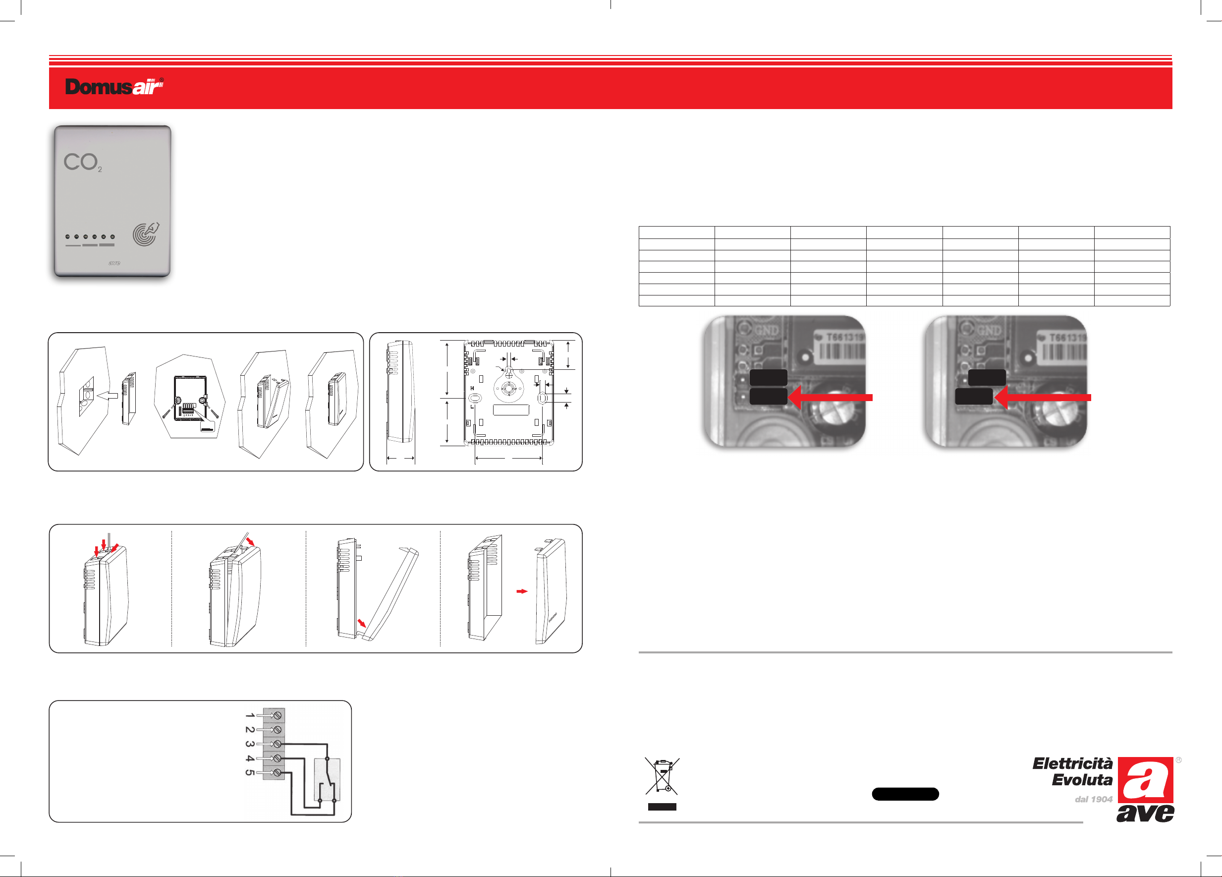
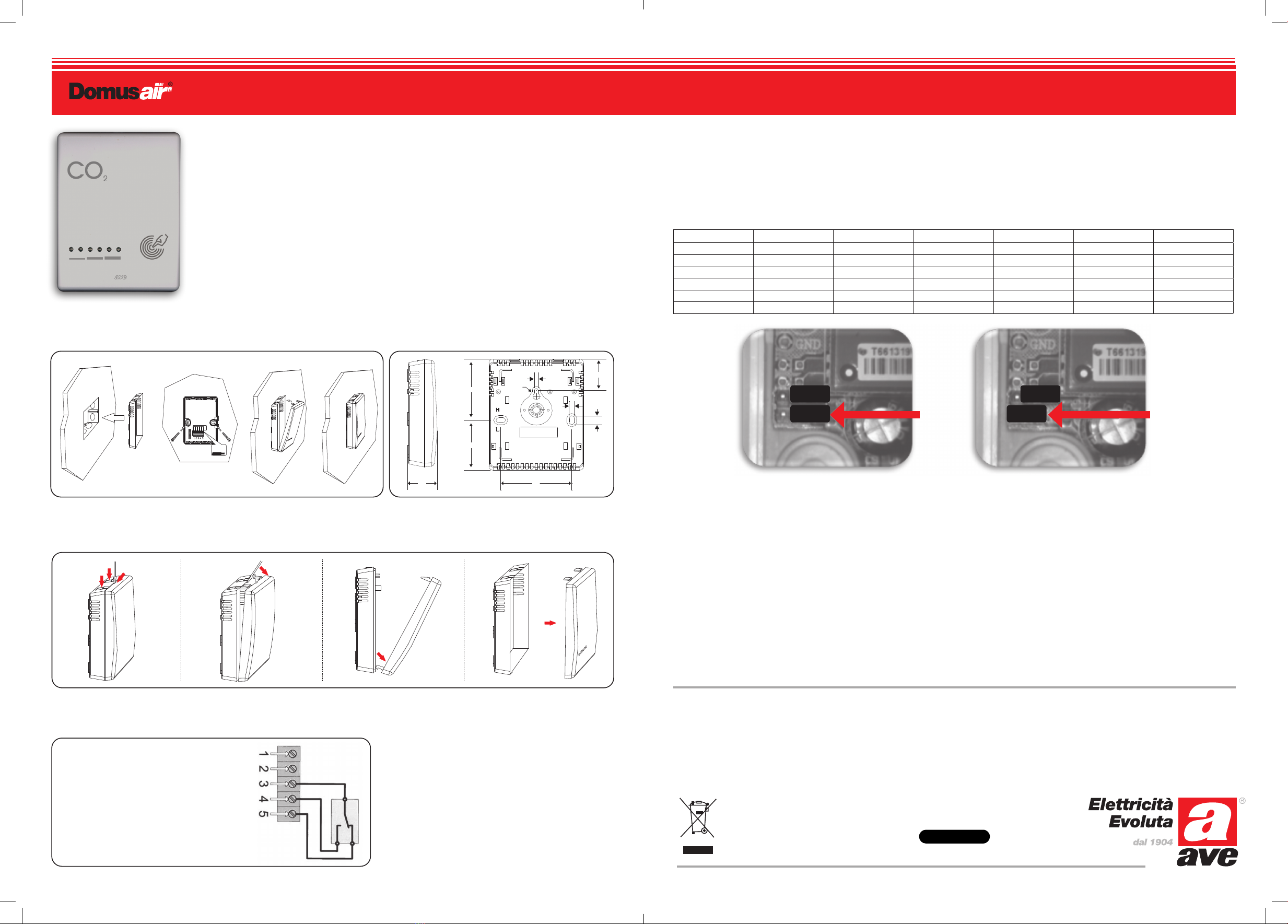
6) SOGLIE DI INTERVENTO
All’interno del dispositivo è presente un ponticello (J1) per la selezione della soglia d’intervento del relè, nel funzionamento automatico (AUTO).
Il ponticello aperto (Fig. 6a - default) seleziona la soglia a 1000 ppm; chiudendolo (Fig. 6b) si imposta la soglia a 1500 ppm.
Per effetto dell’isteresi di 300 ppm, la diseccitazione del relè avverrà quando la concentrazione di CO2 scenderà, rispettivamente, a 700 ppm e a 1200 ppm.
• Tensione nominale: 100 – 240 V~
• Frequenza di rete: 50/60 Hz
• Assorbimento max: <1,8W @230V~
• Temperatura e Umidità Relativa di riferimento: 25°C UR 65%
• Campo Temperatura Ambiente di Funzionamento: da 0°C a +50°C
• Umidità Relativa Massima: 95% a 35°C
• Altitudine max: 2000m s.l.m.
• Campo di misura: da 400 a 2000 ppm CO2
• Grado di protezione: IP20
• Soglia di intervento: 1000 ppm CO2 (default) 1500 ppm CO2 (impostabile)
• Isteresi sulla soglia: 300 ppm CO2
• Accuratezza: ± 40 ppm +3% lettura (tra 400 e 1200 ppm)
• Tempo di risposta tipico: < 2 minuti con variazione concentrazione del 90%
• Intervallo di misura: 4s
• Tempo di accensione: < 2 minuti operativo 10 minuti max accuratezza
• Metodo di misura: NDIR (non-dispersive infra-red). Ottica dorata; algoritmo logico brevettato di
auto calibrazione; campionamento diffuso.
• Stabilità: < 2% sull’intera vita del sensore (15 anni)
• Commutatore frontale: AUTO-ON-OFF.
• Tempo anti riciclo (in AUTO): 10 minuti (periodo minimo di ON o OFF)
• Tipo di azione: Tipo 1B
7) CARATTERISTICHE TECNICHE
Con lo scopo di migliorare i propri prodotti, AVE S.p.A. si riserva il diritto di modificare le caratteristiche tecniche in qualsiasi momento e senza preavviso mantenendo funzionalità e destinazione d’uso. Oltre
a quanto già descritto, le seguenti caratteristiche tecniche si riferiscono alla temperatura ambientale di 20°C (+/- 5°C) e ad un uso normale dell’apparecchio (ambiente residenziale).
ppm CO2L1 - BLU L2 - BLU L3 - VERDE L4 - GIALLO L5 - ROSSO L6 - ROSSO
C < 600 ON
600 < C < 800 ON ON
800 < C 1000 ON
1000 < C < 1500 ON
1500 < C < 2000 ON
C > 2000 ON ON
6028
45
55
28
3
Ø 6
4.5
8
ATTENZIONE: Evitare il posizionamento in ambienti molto umidi, vicino a sorgenti
di vapore, in punti soggetti all’irraggiamento solare diretto o in ambienti con
temperature al di fuori dei limiti indicati.
Per non danneggiare il sensore CO2ad infrarossi interno, evitare urti o scuotimenti
del rivelatore.
Morsetto 1: L alimentazione 230 V~
Morsetto 2: N alimentazione 230 V~
Morsetto 3: C comune contatto in scambio
Morsetto 4: contatto in scambio NO (normalmente aperto)
Morsetto 5: contatto in scambio NC (normalmente chiuso)
4
3
3.1 3.2 3.3 3.4
J1 J1
NOTE
Per la durata e le condizioni di garanzia dei singoli prodotti vedasi www.ave.it e il catalogo commerciale vigente. I prodotti devono essere commercializzati in
confezione originale, in caso contrario al rivenditore e/o installatore è fatto obbligo di applicare e di trasmettere all’utilizzatore le istruzioni che accompagnano il prodotto
e/o pubblicate su www.ave.it e sul catalogo commerciale vigente. I prodotti AVE sono prodotti da installazione. Vanno installati da personale qualificato secondo le
normative vigenti e gli usi, rispettando le istruzioni di conservazione, d’uso e di installazione di AVE S.p.A. Si richiede inoltre il rispetto delle condizioni generali di vendita,
note, avvertenze generali, avvertenze garanzie, reclami e avvertenze tecniche per l’installatore riportate su www.ave.it e sul catalogo commerciale vigente.
PRIMA DI INSTALLARE SISTEMI E AUTOMATISMI È VIVAMENTE CONSIGLIABILE FREQUENTARE UN CORSO DI FORMAZIONE, OLTRE LA LETTURA ATTENTA DELLE ISTRUZIONI
www.ave.it
800 015 072
International Trademark
registration n°
327040 - 942905 - 330600