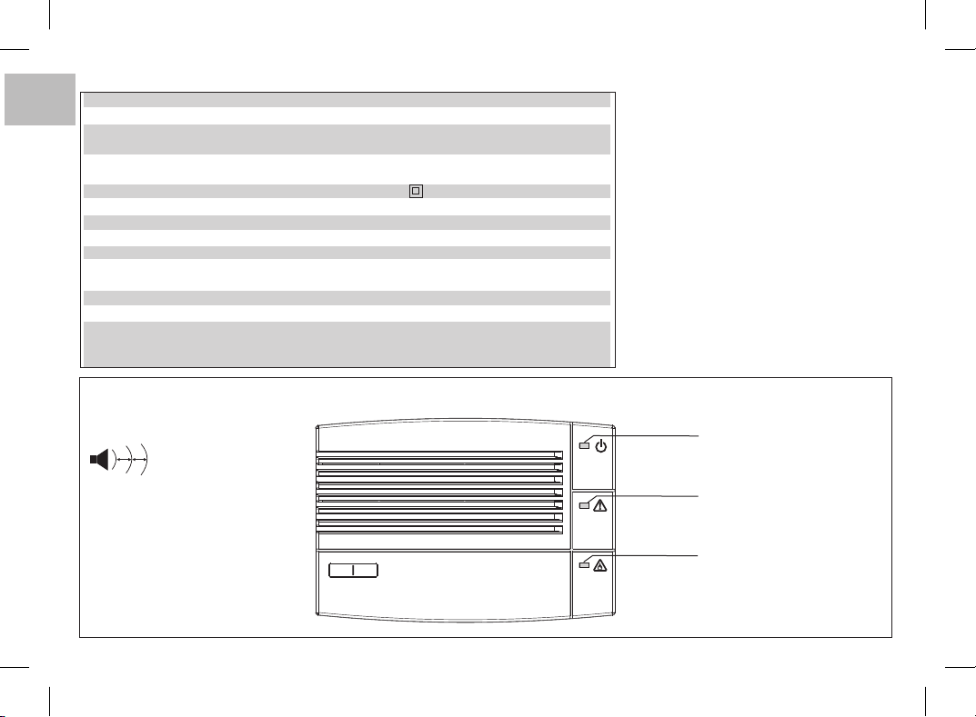
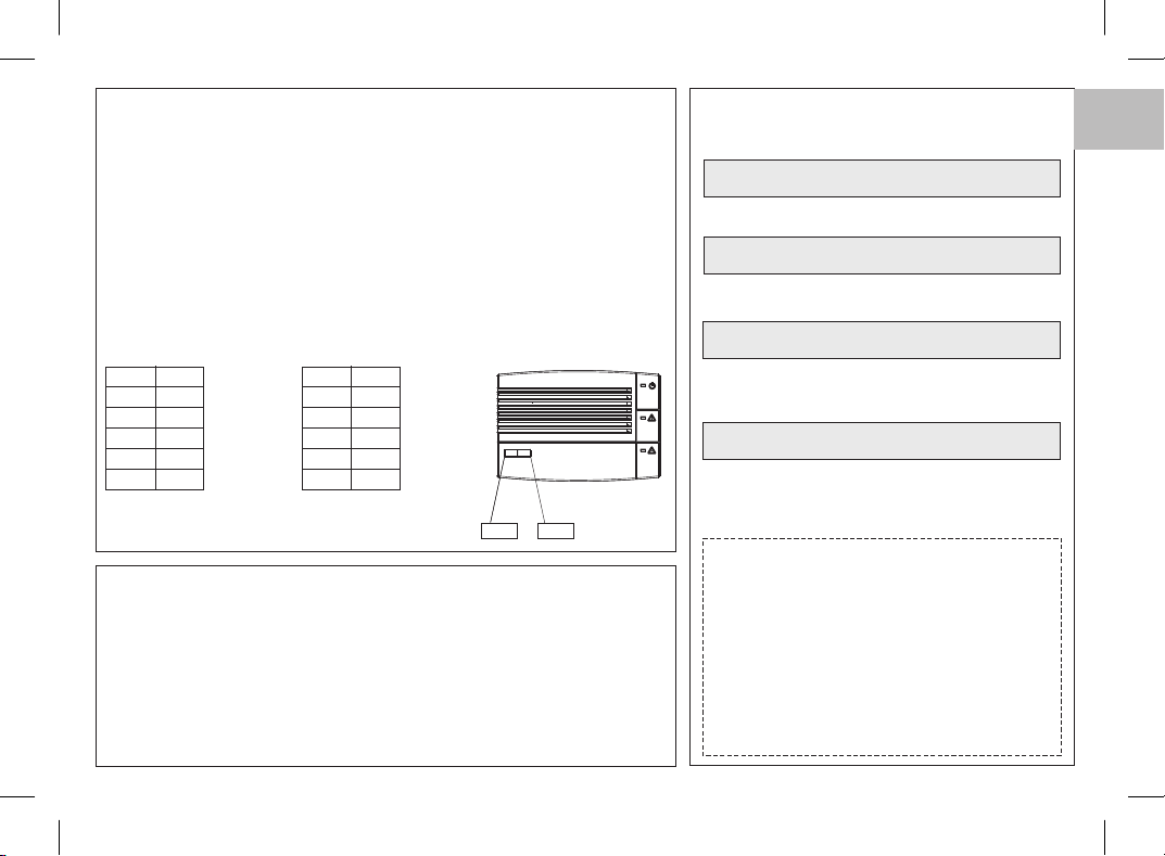
1.u - ACCENSIONE E NORMALE FUNZIONAMENTO
All’accensione o dopo una caduta di rete l’apparecchio rimane per minuto1 in uno stato
non operativo (non rileva gas), necessario per il riscaldamento della sonda (fig. 2), quindi
l’apparecchio passa allo stato operativo (fig. 3)."normale funzionamento"
ISTRUZIONI D’USO PER L’UTENTE Attenzione: esiste la possibilità che nell'ambiente si
avverta odore di gas prima che l'apparecchio dia l'allarme.
5
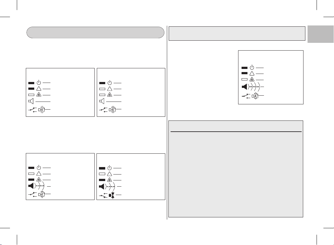
LED verde - acceso
LED giallo - acceso
LED rosso - spento
Buzzer - spento
Relè - disattivato
(Elettrovalvola aperta)
Fig. 2 - Stato operativo “funzio-
namento non operativo”
LED verde - acceso
LED giallo - spento
LED rosso - spento
Buzzer - spento
Relè - disattivato
(Elettrovalvola aperta)
!
Fig. 3 - Stato operativo “normale
funzionamento ”
!
2.u - SEGNALAZIONE PRESENZA DI GAS E ALLARME GAS
Se la concentrazione di gas nell’ambiente supera il valore limite d’intervento,
l’apparecchio segnala tale situazione accendendo il LED rosso di allarme e
contemporaneamente il buzzer emette un suono intermittente (fig. 4).
Se la situazione di allarme presenza gas permane per un tempo di circa 30 secondi, il
relè dell’apparecchio si attiva comandando la chiusura della eventuale elettrovalvola
collegata (fig. 5).
LED verde - acceso
LED giallo - spento
LED rosso - acceso
Buzzer - 1 segnale al sec.
Relè - disattivato
(Elettrovalvola aperta)
Fig. 4 - Stato di “allarme presenza
gas”
!
LED verde - acceso
LED giallo - spento
LED rosso - acceso
Buzzer - 1 segnale al sec.
Relè - attivato
(Elettrovalvola chiusa)
Fig. 5 - Stato di “allarme presenza
gas e attivazione del relè”
!
1s 1s
Quando la concentrazione di gas nell’ambiente si riduce a valori inferiori al valore
limite d’intervento, l’apparecchio ritorna allo stato operativo "normale
funzionamento" e tutte le segnalazioni di allarme cessano, il relè si disattiva (fig. 3).
3.u SEGNALAZIONE GUASTI-
Il LED giallo acceso fisso contem-
poraneamente all’emissione di brevi
segnali acustici del buzzer, indicano
sempre uno stato di guasto o
malfunzionamento dell’apparecchio,
rilevato dal suo sistema di
autodiagnosi (fig. 6).
LED verde - acceso
LED giallo - acceso
LED rosso - spento
Buzzer -
!
Fig. 6 - Segnalazione guasti e
malfunzionamenti
ATTENZIONE!: in caso di segnalazione di stato di “guasto o
malfunzionamento” chiamare l’installatore.
Relè - disattivato
(Elettrovalvola aperta)
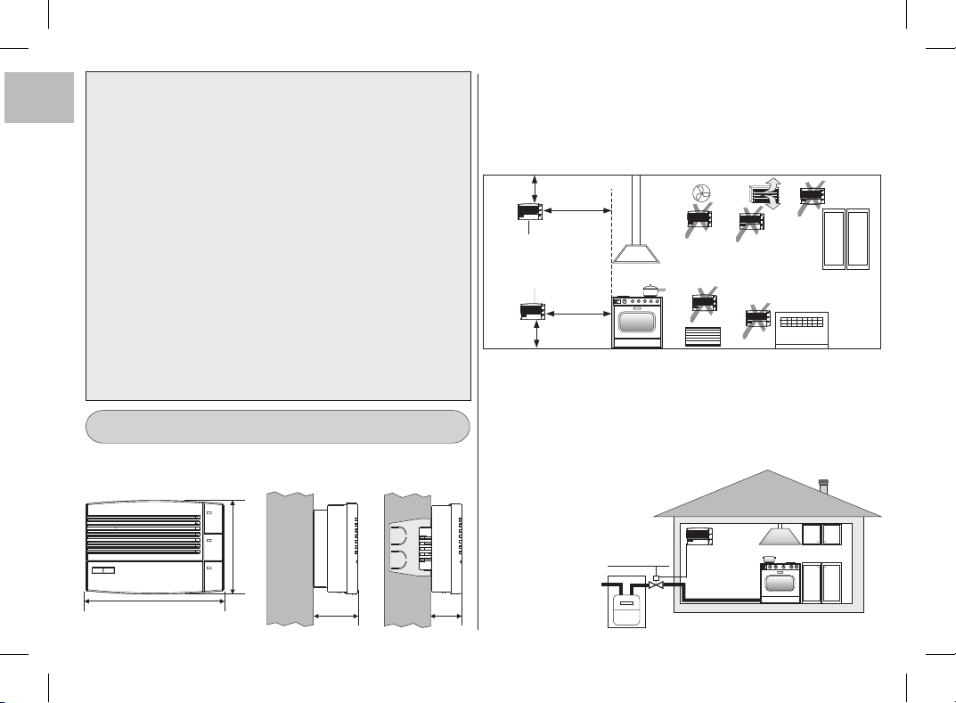
ATTENZIONE! IN CASO DI ALLARME
• ESTINGUERE TUTTE LE FIAMME LIBERE, INCLUSI I MATERIALI
FUMANTI.
• SPEGNERE TUTTI GLI APPARECCHI A GAS.
• CHIUDERE IL RUBINETTO DEL CONTATORE DEL GAS O DELLA
BOMBOLA GPL.
• NON ACCENDERE O SPEGNERE LUCI; NON AZIONARE APPARECCHI
O DISPOSITIVI ALIMENTATI ELETTRICAMENTE.
• NON USARE IL TELEFONO NELL'EDIFICIO CON SOSPETTA PRESENZA
DI GAS.
• APRIRE PORTE E FINESTRE PER AUMENTARE LA VENTILAZIONE
DELL’AMBIENTE.
Se l’allarme cessa è necessario individuare la causa che l’ha provocato e
provvedere di conseguenza.
Se l’allarme continua e la causa di presenza di gas non è individuabile o
eliminabile, abbandonare l’immobile e, dall’esterno, avvisare il servizio di
emergenza.
1s 1s
Brevi segnali
acustici
IT