Huberg RIVELGAS PLUS User manual

User Manual
VERSION 3.0

Form creation date: 01.04.2008 - SpKa
Document creation date: 03.10.2019- RC
2 /21
Data creazione modulo: 01.04.2008 - SpKa
Data creazione documento: 04.06.2019- PG
O
O
U
UR
R
P
PR
RO
OD
DU
UC
CT
TS
S
G
GA
AS
S
S
SA
AF
FE
ET
TY
Y
The professional instrument for
the detection and localization
of gas leaks for CH4 e C3H8
with Bluetooth and GPS.
There is also a version with an
Ethane sensor.
Set of probes for all
purposes to use with
HUBERG instruments:
carpet probe, sucker
probe, flexible probe,
hand held probe and
extendible probe.
The new portable instrument
for gas leak detection and
localization of gas leaks for
CH4 e C3H8 and for toxic gas
(O2, CO, H2S)
Portable instrument for
verifying the calibration
and the flow rate.
Instrument for the personal
safety, for HC (CH4 e C3H8)
and toxic gases (O2, CO,
H2S).
Portable instrument for
the detection and
localization of micro
gas leaks (CH4 e
C3H8) and for
personal safety (O2,
CO, H2S).
Portable instrument for the
detection of methane and
propane.
The portable gas
chromatograph for the
measurement and
analysis of odorants in
gas distribution
networks.
Explosion-proof vacuum
aspiration pump to drain
residual gas from the ground.
Instrument for the
measurement of THT in
network.
Special vehicles for preventive and systematic
gas leak survey in real-time (selectivity IR
methane detection, GPS on board). System
controlled by computer and all the survey can
be connect to the company cartographical
system.

Form creation date: 01.04.2008 - SpKa
Document creation date: 03.10.2019- RC
3 /21

Form creation date: 01.04.2008 - SpKa
Document creation date: 03.10.2019- RC
4 /21
Index
USER MANUAL .................................................................................................................................................................... 1
1 GENERAL DESCRIPTION ....................................................................................................................................... 5
2 DEVICE LAYOUT................................................................................................................................................... 6
2.1 KEYBOARD AND DISPLAY LAYOUT ......................................................................................................... 7
3 FUNCTIONING ..................................................................................................................................................... 8
3.1 TURNING ON ................................................................................................................................... 8
3.2 SWITCHING PROCESS MODE ............................................................................................................... 9
3.3 TURNING OFF .................................................................................................................................. 9
3.4 BACKLIGHT ...................................................................................................................................... 9
3.5 ALARM ........................................................................................................................................... 9
3.6 TOXIC GASES .................................................................................................................................. 10
3.7 AUTOZERO .................................................................................................................................... 10
3.8 SAVE DATA (OPTIONAL) ................................................................................................................ 10
3.9 MENU .......................................................................................................................................... 11
3.10 POFF ........................................................................................................................................... 11
4 BATTERY CHARGE ............................................................................................................................................. 13
5 MAINTENANCE AND PERIODICAL CALIBRATION ............................................................................................... 14
6 WARRANTY ....................................................................................................................................................... 14
7 APPENDIX A – SAFE USE OF THE INSTRUMENT ...................................................................................................... 17
8 Appendix B - Information on Disposal for Users of Waste Electrical & Electronic Equipment (private households)
19

Form creation date: 01.04.2008 - SpKa
Document creation date: 03.10.2019- RC
5 /21
1 GENERAL DESCRIPTION
RIVELGAS plus / EX-PEX plus / Rivelgas Combi are a new family of portable devices for localization of
gas leak and for personal safety. Depending on the device model, they are used either to check pipes, gas
leak detection or for personal safety. It was conceived to be light for portability, and easy to use.
Measured gas concentration is shown on the display. Different scales are available according to the
different models of device: PPM, LEL and VOL.
Alarm threshold can be set by user navigating menu options. Other informations are shown directly
on the display (eg. Battery level, pump status, buzzer status, etc). Power is supplied by NiMH batteries,
which guarantee between 8 to 14 hours of working in nominal conditions, depending on the model (see
datasheet) and can be recharged using the proper battery charger.
The electronics were developed, certified and manufactured according to European Ex directive and
and in compliance with international specifications for safety in environments with explosion risk.
In hazardous environment, the user must take care of the EN 1127-1:2007 (Explosive atmospheres.
Explosion prevention and protection. Basic concepts and methodology ) and the BGR 132 (German
directive :“Vermeidung von elektrostatischer Aufladung”) .
Warning: battery has to be charged in a safe place.

Form creation date: 01.04.2008 - SpKa
Document creation date: 03.10.2019- RC
6/21
2 DEVICE LAYOUT
Fig. 1
1. Sensor (if present)
2. Flexible pipe (if present)
3. Alarm led
4. Buzzer
5. LCD Display
6. Battery charger connector
7. Keyboard
8. Gas output
Some parts models could be different depending on the models.

Form creation date: 01.04.2008 - SpKa
Document creation date: 03.10.2019- RC
7/21
2.1 Keyboard and display layout
Fig. 2
The device has a keyboard with three keys in order to enter the menu.
KEY “OK/START” is used to:
1. turn on/off the device
2. enable/disable backlight of display
3. confirm/look through menu.
KEY “Up/menu” is used to:
1. enter the menu
2. increase set values.
KEY “Down” is used to:
1. decrease set values.
2. Save measured data (Optional)
3. Start the pump again when it is in POFF

Form creation date: 01.04.2008 - SpKa
Document creation date: 03.10.2019- RC
8/21
3 FUNCTIONING
3.1 Turning on
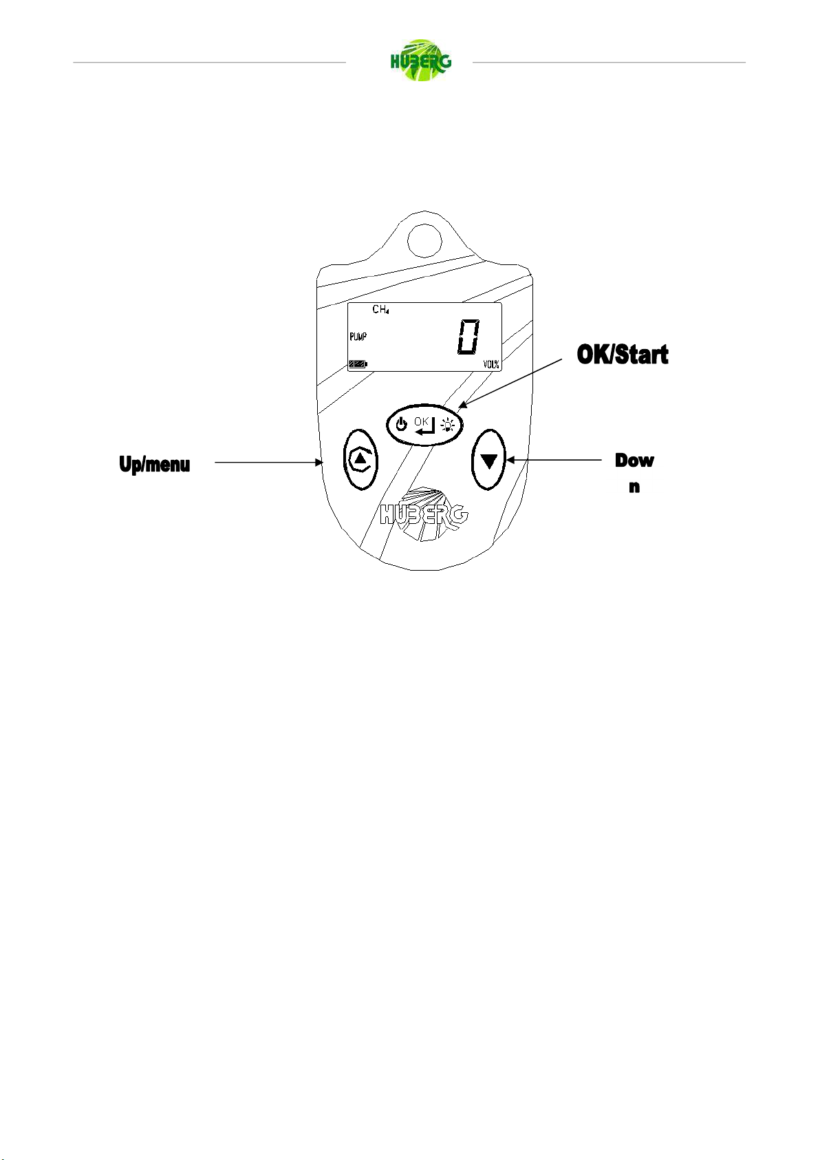
In order to turn on the device, press “OK/Start” key until display shows “On”, then release the key.
After switching on the instrument, and before operational use, the instrument performs these check
tests:
Display lights on to test proper functioning.
The word “SOFt” appears on screen, followed by the software release version number (eg.:
“2.0”).
The word “Sn” appears on screen, followed by the instrument’s serial number (eg.: “7734”).
The word “tAr” appears on screen, followed by the month and year of date of last calibration
(eg.: “11” and “2009” meaning November and 2009 respectively).
Multi-process instruments only (mono-process instruments skip to next step): a scrollable
menu appears on screen, with the process abbreviations
“EXPL”, used for personal safety 100%, diffusion mode
“1” and “VOL” symbol, for Rivelgas Plus 1% with pump
“100” and “VOL” symbol, for Rivelgas Plus 100% with pump
“AUTO”, for RIVELGAS plus 1% - 100% with pump
“OFF”, to turn off the instrument without activating any process.
“GAS TYPE” for multigas instrument
To choose the desired process, scroll the menu with “Down” key and then press “Ok”. Note: available
processes may differ through different device models.
The word “CAL” appears on screen, which means that the instrument has started and auto
calibration step. Auto calibration steps include:
oPump powered processes only: pump stops and restart, to check proper pump
functioning.
oMoving dashed lines appear on screen
oLed blinks, to check proper led functioning
oBuzzer beeps, which means end of auto calibration steps.

Form creation date: 01.04.2008 - SpKa
Document creation date: 03.10.2019- RC
9/21
oIn case the instrument notices sensor malfunctioning, the word “S Er” appears on
screen, and buzzer beeps for 5 seconds, before the instrument switches off.
Device is ready to use and measure is shown.
WARNING: in order to have a correct calibration of the device, it has to be turn on in a place with no
gas.
3.2 Switching process mode
Multi-process instruments only: to switch current instrument process, device must be turned off and
on.
3.3 Turning off
To turn off the instrument, press “OK/Start” key until the end of counter 4 – 3 – 2 – 1 – OFF. If the
key is released before “OFF”, turning off process is stopped.
Device turns off automatically when batteries are discharged, after showing “C-OFF” on display.
3.4 Backlight
To turn on or off backlight, press “OK/Start” key: if the light is off, it will be turned on and vice versa.
3.5 Alarm
After turning on, the instrument measures continuously gas concentrations in medium. When the
measure exceeds alarm threshold, leds flash and buzzer sounds.
The device has two alarm thresholds: one called system alarm (not modifiable by user) and one
called user alarm, set by user. Device sets itself in alarm condition when one of the two alarm thresholds
is reached. When user alarm is exceeded, buzzer can be turned off entering menu and disabling buzzer

Form creation date: 01.04.2008 - SpKa
Document creation date: 03.10.2019- RC
10/21
(system alarm cannot be turned off). Led alarm will flash independently. When system alarm is reached,
buzzer will sound and it cannot be turned off. Led alarm will flash.
For Ex-Pex 09 model: once measurement exceeds system threshold (generally 2,2%VOL), the display
will show a blinking value of 2,2% (indicating that true measurement may fall above that value), and
buzzer will sound with higher frequency.
3.6 Toxic gases
For devices with toxic gas sensor, the display shows alternatively gas or toxic gas concentrations. If
one of these will exceed alarm threshold, the display shows only the one which is over threshold. If the
other gas will exceed its threshold too, display will show again both gases switching alternatively.
3.7 Autozero
It is possible reset the zero of device only if gas measurement falls under 2000ppm, by pressing
“Up/Menu” key and then “Down” key. “AU-0” is shown on display when applied.
3.8 Save data (OPTIONAL)
On request in the instrument of Rivelgas Family have the ability to save measured values, and
download and store them on PC through appropriate software for later processing.
To save the value seen on display, you have to press “Down” key. “SAUE” word will appear on
display, followed by a number, which represents memory position. This implies the value was
successfully stored. Otherwise, if memory is full, the word “FULL” will appear on display, and the new
value will not be stored. Memory sizes vary between models.
In order to manage device’s memory, you should use the “Data Download Software for Ex-
pex+/Rivelgas+”.
3.9 Menu
To enter the menu, press “Up/Menu” key. A little wrench is shown on left side of display.

Form creation date: 01.04.2008 - SpKa
Document creation date: 03.10.2019- RC
11/21
3.10 PoFF
In the instruments with pump if there is an occlusion of the tube the instrument block the pump in
order to protect the instrument. In order to start the pump again you must click on “Down” key.

Form creation date: 01.04.2008 - SpKa
Document creation date: 03.10.2019- RC
12/21
“SCAL” writing is displayed showing
the selected scale. User can choose
ppm/vol or lel/vol scale. For
“GAS” is shown and below selected gas
symbol is shown. If the instrument is calibrated
only for Methane this entry is not displayed.
When “Up/Menu” key or “Down” key are
pressed, gas switches to other configuration
(f.e. C3h8)
“b OFF” is shown if the buzzer is off or
“b ON” if it is on. When “Up/Menu” key or
“Down” key are pressed, writing changes
in “b ON” or “b OFF” if the buzzer was off
or on respectively. This is in order to silent
the buzzer when user alarm threshold is
exceed.
“ALL” writing and then alarm threshold
are shown
Description
Confirm and
exit menu
Confirm and
show next entry
Confirm and
show next entry
Confirm and
show next entry
OK/Start
Change
Change
Change
Increase
threshold
value
Up/Menu
Change
Change
Change
Decrease
threshold
value
Down
Only for RVG+ 01, 02, 04,
05, 06 and 09 and for
COMBI 01, 02, 04, 05, 06
and 10
Only for RIVELGAS
plus/Combi and EX-PEX
plus with more than one
calibration gas (CH4 and
C3h8)
Optional

Form creation date: 01.04.2008 - SpKa
Document creation date: 03.10.2019- RC
13/21
4 BATTERY CHARGE
To charge batteries, switch off the instrument and insert it in the charger support (see fig. 3). A LED
will indicate battery charge state.
Led flashes once per second: it means that it is charging batteries in fast-charge mode.
Led flashes twice per second: it means that it is charging in maintaining/trickle charge mode.
Maintaining-charging is never stopped and it permits to have full charged batteries in order to have
always the maximum device autonomy in operational situation.
Fig. 3
When the docking support is connected to the net, the led blinks two times quickly.
IMPORTANT: batteries has to be charged in safe places and without gas.
IMPORTANT: in case of unused device for long time, the device may not power on because of battery
inactivity. could. If this happens, charge the device for at least 16 hours.

Form creation date: 01.04.2008 - SpKa
Document creation date: 03.10.2019- RC
14/21
5 MAINTENANCE AND PERIODICAL CALIBRATION
For a proper operation and good reliability of the device, QED Environmental Systems Limited
suggests to control and calibrate the instrument periodically, and at least, once a year.
It is reminded that QED Environmental Systems Limited releases a calibration certificate (ISO 9001)
after each instrument calibration.
6 WARRANTY
The device is guaranteed against production defects according to law.
During warranty, QED Environmental Systems Limited will repair every defect in fabrication.
Warranty does not cover damages if the device has been used improperly. Warranty will lose validity if
repairs are not completed by QED Environmental Systems Limited or an authorized service distributor.
This guarantee is valid in all countries where QED Environmental Systems Limited and/or an authorized
agent are distributing RIVELGAS. QED Environmental Systems Limited gives no warranty on the
instrument calibration.
IMPORTANT
Please read the instructions carefully before using the instrument to make it work perfectly. No guarantee is granted if the device is not
handled according to the instructions written in this manual. QED Environmental Systems Limited is at your disposal for any further
information you may want concerning use and maintenance of the instrument.
PLEASE NOTE
QED Environmental Systems Limited is constantly committed to develop and improve its products, thus accepts no liability for technical
modifications carried out without notice. For the same reason we take no responsibility for rightness of information and images in this manual.

Form creation date: 01.04.2008 - SpKa
Document creation date: 03.10.2019- RC
15/21

Form creation date: 01.04.2008 - SpKa
Document creation date: 03.10.2019- RC
16/21

Form creation date: 01.04.2008 - SpKa
Document creation date: 03.10.2019- RC
17/21
7 7 APPENDIX A – SAFE USE OF THE INSTRUMENT
INTRODUCTION
This safety instruction is for installing, working and for the maintains of the gas leak detector
instrument RIVELGAS/EXPEX type and for use it in areas with potentially explosive atmospheres. The
equipment covered by these instructions is characterized by the following marking:
II 2G Ex ib d IIC T4 Gb
The information contained in these safety instructions must be followed in addition to the warnings
in the user manual supplied to the customer.
GENERAL
Instrumentation equipped with battery and sensors for the detection of gas leaks. Used for the
detection of leaks on the gas meters and in the distribution gas network, and finally how to use it for
personal safety.
INSTALLATION
Suitability of equipment into installation site
In the case of use in areas with danger of explosion must verify that the type of detector is suitable at
the classification of the area and at the flammable substances in the system. The essential requirements
of security against the risk of explosion in dangerous areas are established by the European Directive
2014/34/EU (in respect of equipment) and 1999/92/CE of 16 December 1999 (as regards facilities). The
criteria for classifying areas at risk of explosion are explained in the norm EN60079-10. The technical
requirements of electrical installations in dangerous areas are established in the EN60079-14.
In the label on the instrument, in addition to functional data, there are also a referred to the
references to the notified responsible for certification.

Form creation date: 01.04.2008 - SpKa
Document creation date: 03.10.2019- RC
18/21
Security Summary
II 2 G
Instrument for detecting the presence of gases or vapors of category 2 suitable
for zone 1 with redundancy for zone 2
Ex ia d
Instrument with
intrinsically safe circuits
and chamber of
analysis for Gas
with
explosion-proof enclosure
IIC
Equipment
for gasses of group IIB and IIA
T4
Temperature class
of equipment (surface temperature)
CE
Mark of conformity to
the applicable European Directives
Mark
of conformity for Directive
2014/34/EU
CESIxxATEXyyy
Name
of the
laboratory
that issued the
CE
certificate;
xx
= Year
of issue;
yyy
=
number of the certificate.
XXXX
Number
of the Notified Organization
conducting the
surveillance
system
production
Notes:
a) The devices for Group IIB are suitable also for group IIA;
b) Equipment with temperature class T4 are also suitable for all the substances with higher class
temperature (T3, T2, T1);
Other precautions for the usage
The charging of the batteries must be in a safe place with the appropriate external adapter.
Do not open the instrument by unauthorized personnel, the opening of which invalidate the
certification.
TESTING AND MAINTENANCE
The checks and maintenance of certified equipment should be performed according to the criteria of
the standard EN60079-17.
REPAIR
In the event of malfunction or damage, it is recommended to send the equipment to QED
Environmental Systems Limited or an authorized service distributor who will repair it.

Form creation date: 01.04.2008 - SpKa
Document creation date: 03.10.2019- RC
19/21
8 APPENDIX B - INFORMATION ON DISPOSAL FOR USERS OF WASTE
ELECTRICAL & ELECTRONIC EQUIPMENT (PRIVATE HOUSEHOLDS)
This symbol on the product(s) and / or accompanying documents means
that used electrical and electronic products should not be mixed with general
household waste. For proper treatment, recovery and recycling, please take
this product(s) to designated collection points where it will be accepted free
of charge.
Alternatively, in some countries you may be able to return your products
to your local retailer upon purchase of an equivalent new product.
Disposing of this product correctly will help save valuable resources and
prevent any potential negative effects on human health and the
environment, which could otherwise arise from inappropriate waste
handling.
Please contact your local authority for further details of your nearest designated collection point.
Penalties may be applicable for incorrect disposal of this waste, in accordance with you national
legislation.
For business users in the European Union
If you wish to discard electrical and electronic equipment, please contact your dealer or supplier for
further information.
Information on Disposal in other Countries outside the European Union
This symbol is only valid in the European Union. If you wish to discard this product please contact
your local authorities or dealer and ask for the correct method of disposal.

Form creation date: 01.04.2008 - SpKa
Document creation date: 03.10.2019- RC
20/21
www.huberg.com
This manual suits for next models
2
Table of contents
Other Huberg Gas Detector manuals
Popular Gas Detector manuals by other brands

Tokyo Gas Engineering Solutions Corporation
Tokyo Gas Engineering Solutions Corporation LaserMethane SMART LM2B03N-SBA operating instructions

Vighnaharta
Vighnaharta TrueSafe TS12CLR user manual

New Cosmos Electric
New Cosmos Electric KS-7D instruction manual

Sensitron
Sensitron MULTISCAN++/S1-32B Installation and use manual

Gas Clip Technologies
Gas Clip Technologies Multi Gas Clip Infrared quick start guide

BEINAT
BEINAT GSH246 Series manual