Gas-Tec GSP-501FT User manual

Instruction manual
Automatic Air Sampling Pump
GSP-501FT
Important Notices
Please read this manual thoroughly before using this product.
Keep this manual with this product.
Gastec Corporation
8-8-6 Fukayanaka, Ayase-City, Kanagawa, 252-1195
Japan
TEL.0467-79-3910 FAX.0467-79-3979
IM23GSP501FTE1

1
Table of Contents
1. Introduction
…………………………………………………………………………
2
2. For Safe Operations
…………………………………………………………………
2
3. List of Components
…………………………………………………………………
4
4. Design and Basic Features
……………………………………………………………
5
4.1 Names and Functions
……………………………………………………………
5
4.2 Description of the LCD and Operating Buttons
…………………………………
7
5. Before Use
……………………………………………………………………………
9
5.1 Prepare the Power Supply
………………………………………………………
9
5.1.1 Power Supply
…………………………………………………………
9
5.1.2 How to Install and Replace the AA Batteries
…………………………
9
5.1.3 Relationship between Battery Level Indicator and Sampling Time
……
11
5.2 Flow Rate Conversion Temperature
……………………………………………
12
6. Setting and Operations
………………………………………………………………
13
6.1 Connect Sampling media, tubing, and the Pump
…………………………………
13
6.2 Sampling Mode and Setting Ranges
……………………………………………
14
6.3 Timer Mode
……………………………………………………………………
15
6.4 Volume Mode
……………………………………………………………………
18
6.5 Program Mode
…………………………………………………………………
22
6.5.1 How to Save and Change the Program
…………………………………
22
6.5.2 Sampling by Program Mode
……………………………………………
24
6.6 Repeat Sampling with the Previous Sampling Setting
…………………………
27
6.7 Display of Sampling Information during Sampling Operation
…………………
29
6.8 Display of Setting Information during Sampling Operation
……………………
29
6.9 Stop the Sampling Operation
…………………………………………………
29
6.10 Auto Power Off
………………………………………………………………
29
6.11 Clogging
………………………………………………………………………
30
6.12 Intermittent Operation
………………………………………………………
30
7. Flow Calibration
……………………………………………………………………
31
7.1 About Flow Calibration
………………………………………………………
31
7.2 Calibration Mode
………………………………………………………………
31
7.3 Setting of Flow Rate Conversion Temperature
…………………………………
32
7.4 Setting of the Flow Rate Conversion Temperature of the Calibrator
……………
34
7.5 Zero Point Adjustment
…………………………………………………………
36
7.6 Leak Check
……………………………………………………………………
37
7.7 Flow Calibration Procedures
……………………………………………………
40
8. Maintenance and Inspection
…………………………………………………………
43
8.1 Replacing the Dust Filter and O-ring
…………………………………………
43
8.2 Checking the Total Operating Time of the Air Pump
…………………………
44
9. Troubleshooting
………………………………………………………………………
45
10. Specification
…………………………………………………………………………
49
11. Repair and Warranty
…………………………………………………………………
51
11.1 Repair
…………………………………………………………………………
51
11.2 PRODUCT WARRANTY AND DISCLAIMER
………………………………
51
11.3 Recommended Time for Maintenance Parts Replacement
……………………
52
12. Declaration of Conformity
…………………………………………………………
53

2
1. Introduction
Be sure to read the manual before using the product.
Thank you for purchasing our Automatic Air Sampling Pump GSP-501FT.
Please read and understand the manual completely before using this sampling pump.
Also, after reading, keep the manual in a place where it can be referred to at any time.
About this manual
Do not use this product until you understand the manual completely.
When lending or giving this product to a third party, be sure to hand over the manual with this
product.
If the manual is lost or damaged, contact Gastec or your Gastec representative promptly.
This manual contains "2. For Safe Operations" to ensure safe operation. Be sure to read this
section before using this product.
Copyright Notice
The copyright of this document is owned by Gastec Corporation. Therefore, unauthorized
reproduction or duplication in whole or in part is strictly prohibited.
2. For Safe Operations
To use this product properly, be sure to observe the following precautions. The precautions are
critical for safety.
This product should be used by specialists with knowledge of environmental measurements.
This product is an automatic air sampling pump. Do not use the product for purposes other than
air sampling of various Gastec gas detector tubes, sorbent tubes, etc.
Gastec Corporation shall not take responsibility for any accidents that occur in
situations that are contrary to the above items.
The precautions in this manual are classified by the following indications according to the
magnitude of the danger or damage and the degree of the imminence.
The shape, size, and position of the figures and illustrations may be different from the actual
product.
Symbol marks with the following definitions are used to ensure proper and safe use of the
product.
Warning
This means that death or serious bodily injuries may result if not observed.
Caution
This means that minor or moderate bodily injuries may result if not observed.
Note
This means operational tips for proper use of the product to prevent functional
failures.

3
Warning
This product is NOT approved as explosion-proof. Do not use this product in hazardous
locations.
△Note
Ensure to perform an inspection before use to ensure that the product operates properly.
Avoid water entering in air routing. The suction of water may damage the sampling train (air
pump, flow sensor, etc.).
Do not block the air outlet port. Flow resistance may cause errors in the product flow rate
and integrated volume.
Do not use this product in high temperatures. Malfunction or mechanical failure may result.
This product is not waterproof. Avoid using this product where it may be exposed to water.
Mechanical failure may result.
Dropping or other significant impacts may cause mechanical failure.
Do not use electromagnetic wave generation devices such as professional radios and amateur
radios within 30cm from this product. If electromagnetic wave generation devices are used
near this product, errors may occur in the measured flow rate.
Do not disassemble or modify the product. The safety and quality of the product cannot be
guaranteed.
Be sure to turn off the power before replacing the battery. Mechanical failure may result.
Do not store the product where it may be exposed to direct sunlight.
Do not store the product where the temperature is above 50°C (122°F) or below -10°C (14°F).
Do not store the product in an extremely dry (humidity 10% or less) or high humidity (90%
or higher).
Do not store the product where it may be exposed to water, steam, sand, or dust.
If the product will not be used for a long time (one month or more), remove the batteries. If
The product is stored with batteries installed may cause battery drain and mechanical failure
due to battery leakage.

4
3. List of Components
When opening the package please check that all the following items are present.
Item
Product code
Quantity
①
Model GSP-501FT Unit
1
②
Detector Tube Adapter
GSP300-13
1
③
AA Alkaline Batteries
(Panasonic Corporation LR06)
2
④
Dust Filter (5 pcs.)
1
⑤
Tube Tip Holder
722
1
Instruction Manual
1

5
4. Design and Basic Features
4.1 Names and Functions

6
①
Suction Inlet
Connect the detector tube or the sorbent tube using the
attached detector tube adapter or tubing. (The outer
diameter of the inlet is Φ6mm)
②
LCD
Displays the remaining battery power, each measured
value, each set value, current operation mode, previous
records, error information, etc.
In normal mode, the backlight turns on for 10 seconds
when any of the buttons is operated. In calibration mode,
the backlight stays on.
③
Keypad
The pump is operated using six buttons.
For details, see "4.2 Description of the LCD and
Operating Buttons".
④
Status Lamp
The light colour and flashing indicate the operation status.
⑤
Battery Chamber/Battery
Chamber Cover
Set two AA alkaline batteries or AA nickel-metal hydride
batteries in the battery chamber. The battery chamber
cover is opened and closed by sliding it while pressing it
with your finger when replacing the batteries.
⑥
Air Outlet Port
This is the outlet of the sampled air. Connect the tubing
when you want to guide the sampled gas away from this
pump. (The outer diameter: Φ 6.4mm)
⑦
Screw Hole for Attaching a
Tripod
Screw hole for fixing this pump on a tripod.

7
4.2 Description of the LCD and Operating Buttons
●LCD
①
Setting
The bar turns on while each set value is displayed or set.
②
Timer
The bar turns on when setting or operating in timer mode.
③
Constant volume
The bar turns on when setting or operating in Volume Mode.
④
Program
The bar turns on when setting or operating in program mode.
⑤
Program
Number
The number of the saved program turns on when setting or
operating in the program mode.
It flashes while the program is being selected.
⑥
Battery Level
Indicator
(AA Batteries)
The remaining battery power in the battery chamber is displayed in
five levels.
Refer to "5.1.3 Relationship between Battery Level Indicator and
Sampling Time" for remaining battery power.
⑦
Unit
The unit is displayed according to the displayed values.
⑧
Set Value/
Measured value
Each set value is displayed during setting, and each measured value
is displayed during operation. The value being set blinks during
setting.
"FLOW": Display of set instantaneous flow rate/measured
instantaneous flow rate
"TIME": Display of set sampling time/measured sampling time

8
"INTG": Display of set integrated volume /measured integrated
volume
"STBY": Display of set standby time/measured standby time
●Operating Buttons
A
Power Button
Press this button to turn on the power. To turn off the power, press
and hold this button for 2 seconds or longer.
B
Mode Button
Switches mode to the Timer Mode, Volume Mode, Program Mode,
or Previous Sampling Results.
C
Select Button
Switches the items to be changed (instantaneous flow rate,
sampling time, integrated volume, and standby time) in order.
Press this button during pump operation to check the current
sampling operation setting.
D
Increase Button
Press this button to increase the setting value.
(In the program mode, the registration number is switched).
E
Decrease Button
Press this button to decrease the setting value.
(In the program mode, the registration number is switched).
F
START/STOP
Button
Press this button to start and stop (forced termination) the sampling
operation.

9
5. Before use
5.1 Prepare the Power Supply
●5.1.1 Power Supply
The following batteries can be used for GSP-501FT:
Two AA alkaline batteries (accessories)
or
Two AA nickel-metal hydride batteries
△Note
The AA nickel-metal hydride batteries do not come with this product.
This product does not charge the AA nickel-metal hydride batteries.
It is recommended to use AA nickel-metal hydride batteries when the flow rate is high and
the suction load is high, or when the product is used at low temperatures.
●5.1.2 How to Install and Replace AA Batteries
△Note
Ensure to turn off the power before installing or removing the batteries. Mechanical failure
may result.
①
Slide the battery chamber cover toward the rear
side while pressing it, and then open the battery
chamber cover.
②
[When replacing the batteries]
Tilt the body to remove the two AA batteries from
the battery chamber.

10
③
Insert the AA batteries according to the “+” and “-”
indications engraved on the back of the battery
cover.
④
Close the battery chamber cover, and slide it
toward the front side while pressing it until the
cover is locked.
※After locked, confirm if the battery chamber
cover is locked by sliding it toward the back side
without pressing it.
△Note
Note that the power will not be turned on if the battery is installed in the wrong direction.
Check if the battery cover is locked before use. The cover may open due to impact or
vibration, which may interfere with energization and cause unexpected power failure.
If the electrode is dirty, wipe it with a dry cloth before use. Otherwise, this may interfere with
energization, and the power may not be turned on.

11
●5.1.3 Relationship between Battery Level Indicator and Sampling Time
The battery level indicator on GSP-501FT screen indicates the remaining battery power in five levels.
The indication of the battery level indicator and the sampling time are shown below.
Table 1. Relationship between battery level indicator and the sampling time (2 AA alkaline
batteries(Panasonic Corporation LR06)) [typical example]
Sampling condition
Sampling time (hours)
Flow rate
(mL/min)
Load
(kPa)
50
30 ※1
14
11
8
5
2
100
1.5
28
19
13
7
3
100
20 ※2
15
11
9
5
2
200
2
23
16
12
6
3
500
10
5
4
3
2
1
※1:An example of using an Ethylene oxide Detector Tube 163TP
※2:An example of using a Formaldehyde Detector tube 91TP
Table 2. Relationship between battery level indicator and the sampling time (2 AA nickel-metal
hydride batteries) [typical example]
Sampling condition
Sampling time (hours)
Flow rate
(mL/min)
Load
(kPa)
50
30 ※1
15
13
5
1
0.3
100
1.5
29
17
7
2
0.5
100
20 ※2
17
14
5
2
0.3
200
2
23
20
10
4
1.2
500
10
6.4
6
5
1
0.3
△Note
The values in Tables 1 & 2 are typical examples at a temperature of 25°C and atmospheric
pressure of 1 atm. Please note that these values are not guaranteed values. In low-
temperature environments, the sampling time may be shorter than the above tables.
The values in Table 2 are for reference only and vary depending on the manufacturer and
model number of the AA nickel-metal hydride batteries.
When the battery indicator is " ", the battery is running out. Replace the batteries.
If the battery runs out during the sampling operation, the integrated volume and sample
time immediately before the pump stops are recorded as the previous sampling result.

12
5.2 Flow Rate Conversion Temperature
This pump displays the flow rate, adjusts the pump output, and calculates the integrated volume by
converting it to a volume flow at 20°C or 25°C, 101.3 kPa, regardless of the environmental
temperature, as long as it is within the operating temperature range. The set flow rate conversion
temperature is displayed when starting up the pump (factory default conversion temperature: 25°C).
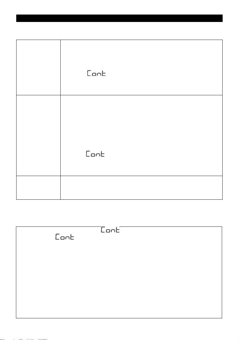
<How to check the flow rate conversion temperature>
Press the "Power Button" to turn on the power.
When activated, the followings are displayed
in order.
①All segments light up (for 2 seconds)
②
Flow Rate Conversion Temperature (for 2
seconds)
③Previous Sampling Results
※Check at the timing of ②above.
↓
(When the flow rate conversion
temperature is 25°C)
Conversion temperature is selectable between 20°C and 25°C.
To change the conversion temperature, refer to "7.3 Setting of Flow Rate Conversion Temperature ".

13
6. Settings and Operations
6.1 Connect Sampling media, tubing, and the pump
Connect the sampling media or Gastec detector tube to the suction inlet using the supplied detector
tube adapter or another tubing before the sampling operation. Connect a tubing prepared by the user
to the air outlet to guide the exhaust away from the pump when necessary.
△Note
Before connecting the detector tube adapter or tubing, check that there is no damage or dust
on the inner wall. Leakage may occur, which may interfere with accurate sampling.
If the suction load is suddenly reduced, the flow rate may not stabilize in some cases (such
as a continuous flow rate variation of 20% or more of the set flow rate). Make sure that the
suction load does not fluctuate suddenly. If the flow rate becomes unstable, stop sampling
once and restart.
Do not block the air outlet port. Flow resistance may cause errors in the instantaneous flow
rate and integrated volume.
The outflow rate from the air outlet port is out of the guaranteed flow rate accuracy.
Also, be careful of the following items regarding placing the pump.
△Note
Select a place with little airflow and little fluctuation of atmospheric pressure and install the
pump with the inclination of the left and right sides within ±10°. If the left or right inclination
is large, the measured flow rate error becomes large.
Place the pump in a stable position. Shock or
vibration can cause errors in flow rate
measurements.
When the suction load is heavy, the pump may move due to vibration depending on the
conditions. When placing the pump on a table, etc., take measures to prevent from dropping.
When used with the tripod, take measures to prevent the tripod from falling over. Otherwise,
mechanical failure may result due to a fall.
For personal sampling purposes, use the dedicated belt loop pump holder (optional product).
14
6.2 Sampling Mode and Setting Ranges
There are three sampling modes: Timer mode, Volume Mode, and Program mode.
Timer mode
After the set time has elapsed, the sampling operation automatically stops.
Select this mode to prioritize the ending time.
[Items to be set and selectable range]
●Flow rate: 50~500 mL/min
●Sampling time: 1 min. to 30 hr.
※Select " " if you wish to sample for a time that exceeds the
selectable range. Stop manually or continue to sample until the battery runs
out.
●Standby time: 0 min to 24 h
Volume Mode
When the integrated volume reaches the set value, the sampling operation
automatically stops.
Select this mode to prioritize the integrated volume.
[Items to be set and selectable range]
●Flow rate: 10~500 mL/min
※When set to 10~49 mL/min, the pump runs intermittently with the flow
rate of 50mL/min. (See "6.12 Intermittent Operation" for details.)
●Volume : 0.010~900.0 L
※The range where the sampling time is within 30 hours
※Select " " if you wish to sample with the integrated volume that
exceeds the selectable range. Stop manually or continue to sample until the
battery runs out.
●Standby time: 0 min to 24 h
Program mode
The sampling setting (Timer mode or Volume Mode) is saved in advance,
and the setting is read out to perform sampling.
This is useful when using the same sampling setting repeatedly.
The maximum number of sampling settings that can be stored is 5.
※Sampling can be performed with the same setting as the previous one by starting the pump while
"Previous Sampling Setting" or "Previous Sampling Result" are displayed.
△Note
The operation is the same when "
" is set for the sampling time in the Timer mode
and when " " is set for the integration flow rate in the Volume Mode.
Even if the flow rate can be set, the actual flow rate may not reach the set flow rate depending
on the load of the sampling media. Refer to "Constant flow rate operating range" in "10.
Specifications" for the maxim load for each set flow rate.
Even if the sampling time and integrated volume can be set, depending on the remaining
battery power, the battery may run out and stop during sampling. Refer to "5.1.3 Relationship
between Battery Level Indicator and Sampling Time" for details.
When the sampling time is less than 5 minutes, the effect of the error from the start of
sampling till the flow becomes stable is large. Therefore, the measured integrated volume in
the case of the timer mode and the measured sampling time in the case of the Volume Mode
may deviate from the range of ±5% of each calculated value.

15
①
When the pump is turned on by pressing the
"POWER Button"
, the flow rate conversion
temperature is displayed for 2 seconds, and then
the sampling results in the previous operation are
displayed.
※When turned on firstly after purchase, the
followings are displayed
Mode: Timer
FLOW: ---
TIME: 0:00
INTG: 0.000L
STBY: ---
Previous sampling results (above is
when purchased)
②
Press "MODE Button” to select the Timer mode.
Press
③
Check that the set value of " Instantaneous flow
rate" is blinking, and
set the desired
instantaneous flow rate with the "Increase
Button" and "Decrease Button". Press and hold
to make fast forward.
[Setting range]
50~500mL/min
※The setting increment is 1mL/min.
(Example) Flow rate: 100 mL/min
↓
Press or
6.3 Timer Mode

16
④
To set the sampling time, press the "SELECT
Button", to make the "Time" setting value blink,
and set the desired sampling
time with the
"INCREASE Button" and "DECREASE
Button”. Press and hold to make fast forward.
[setting range] 0:01 to 30:00 (1 min to 30 h)
※The setting increment is one-minute.
※When the instantaneous flow rate and
sampling time are set, the integrated volume is
automatically calculated,
and the value is
displayed at the "Integrated volume" position.
※Set to " " for continuous sampling.
Setting procedure
When 0:01 is displayed, press "DECREASE
Button” once.
When 30:00 is displayed
, press
"INCREASE Button” once.
(When "Time" is set to " ", "
" is also displayed
at the
"Integrated volume” position)
Press
↓
(Example) Sampling time: 10 min.
↓
Press or
⑤
To set the standby time, press "SELECT Button"
to make the "Standby" setting value blink, then
set the desired standby time with the
"INCREASE Button" and "DECREASE
Button". Press and hold to make fast forward.
[setting range] 0:00 to 24:00 (0 min to 24 h)
※The setting increment is one-minute.
Press
↓
(Example) Standby time: 5 min.
↓
Press or
⑥
Check that the instantaneous flow rate, sampling
time, integrated volume, and standby time are set
correctly.

17
⑦
When the sampling is ready, press and hold the
"START/STOP Button”. The bar at the "SET"
segment disappears and the status lamp flashes
in green, and the sampling operation starts.
※If the standby time is set, the followings are
displayed,
"FLOW": ---
"TIME": ---
"INTG":---
and the sampling operation starts when the
remaining standby time becomes "0:00".
Press and Hold
↓
Pump running
On standby
⑧
After the set sampling time has elapsed, the
sampling
operation is completed and the
sampling result is displayed.

18
⑨
The screen is switched by pressing the "SELECT
Button" and the settings (mode, instantaneous
flow rate, sampling time, integrated volume, and
standby time) for the completed sampling
operation are displayed.
Press
↓
⑩
Press and hold the "POWER Button" to turn off
the power.
Press and Hold
△Note
To repeat sampling with the same settings, press and hold the "Start/Stop Button" in the state
described in ⑧and ⑨above to start the sampling operation.
6.4 Volume Mode
△Note
The integrated volume rate cannot be set to beyond 30 hours of sampling.
See the settable range in the graph below.
Example)
When the instantaneous flow rate is set to 10 mL/min (intermittent run)
Min: 0.01L Max: 18 L (=10 mL/min x 30 h)

19
When the instantaneous flow rate is set to 500 mL/min
Min: 0.01L Max: 900 L (=500mL/min×30 h)
①
When the pump is turned on by pressing the
"POWER Button"
, the flow rate conversion
temperature is displayed for 2 seconds, and then the
sampling results in the
previous operation are
displayed.
Previous sampling result
②
Press "MODE Button" to select the Volume Mode.
Press twice
↓
③
Check that the set value of "Instantaneous flow rate"
is blinking, and set the desired instantaneous flow
rate with the "INCREASE Button" and
"DECREASE Button". Press and hold to make fast
forward.
[Setting range]
10~500mL/min
※The setting increment is 1mL/min.
※When the instantaneous flow rate is set at 10 to
49mL/min, the pump runs intermittently with the
flow rate of 50mL/min. Refer to "6.12 Intermittent
Operation" for details.
(Example) Flow rate: 100 mL/min
↓
Press or
Table of contents
Other Gas-Tec Water Pump manuals


