Gardenline GLSP1002 User manual

Operating Instructions
N16188
Anleitung GLSP 1002_SPK7:Anleitung GLSP 1002_SPK7 27.06.2008 11:25 Uhr Seite 1

After Sales Support TEL: 1300 130 579 WEB: www.rossmac.com
2
Dirty Water Pump
What your 1 year warranty means
Great care has gone into the manufacture of this product and it should therefore provide you with years of
good service when used properly. In the event of product failure within its intended use over the course of the
first year after the date of purchase, we will remedy the problem as quickly as possible once it has been
brought to our attention. In the unlikely event of such an occurrence, or if you require any information about
the product please contact us via our after sales support services, details of which can be found in this manual
and on the product itself.
Anleitung GLSP 1002_SPK7:Anleitung GLSP 1002_SPK7 27.06.2008 11:25 Uhr Seite 2

After Sales Support TEL: 1300 130 579 WEB: www.rossmac.com
3
1
Table of contents
1. Safety instructions page 4
2. Layout page 4
3. Installation page 4
4. Mains connection page 5
5. Areas of application page 5
6. Starting up page 5
7. Maintenance instructions page 5
8. Setting the ON/OFF switching point page 6
9. Technical data page 6
10. Performance data page 6
10. Waste disposal page 6
12. Ordering replacement parts page 6
13. Troubleshooting page 7
Anleitung GLSP 1002_SPK7:Anleitung GLSP 1002_SPK7 27.06.2008 11:25 Uhr Seite 3

After Sales Support TEL: 1300 130 579 WEB: www.rossmac.com
4
Before you put the dirty water pump into operation,
carefully read the following safety regulations and the
operating instructions.
If you give the equipment to any other persons, give
them the operating instructions as well.
Keep these instructions in a safe place.
Packaging
The unit is supplied in packaging to prevent it from
being damaged in transit. The raw materials in this
packaging can be reused or recycled.
1. Safety instructions
Caution!
In stagnant water bodies, garden ponds,
swimming ponds and their surrounding areas the
pump may only be used with an earth-leakage
circuit breaker with an actuating rated current of
up to 30 mA (acc. to VDE 0100 part 702 and 738).
The pump is not designed for use in swimming
pools and paddling pools of any kind or other
bodies of water in which people or animals may
be present during operation.
It is prohibited to operate the pump if a person or
animal is in the danger area.
Ask your electrician!
●Before starting to run your new pump, please have
the following items checked by an expert:
- Ground connection
- Zero conductor
●Safety circuit breaker switch must correspond
to the safety regulations of the power plants
and they must work faultlessly.
●The electrical connections must be protected from
moisture.
●If there is danger of flooding, the electrical
connections must be taken to higher ground.
●Circulation of aggressive fluids, as well as the
circulation of abrasive materials must be avoided
at all costs.
●The pump must be protected from frost.
●The pump must be protected from running dry.
●Access on the part of children should also be
prevented with appropriate measures.
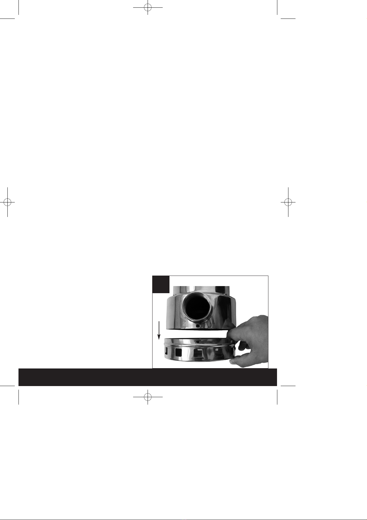
2. Layout (Fig. 1)
1 Handle
2 Integrated cable rewind
3 Universal hose connection
4 Venting
5 Floating switch
6 Cable holder
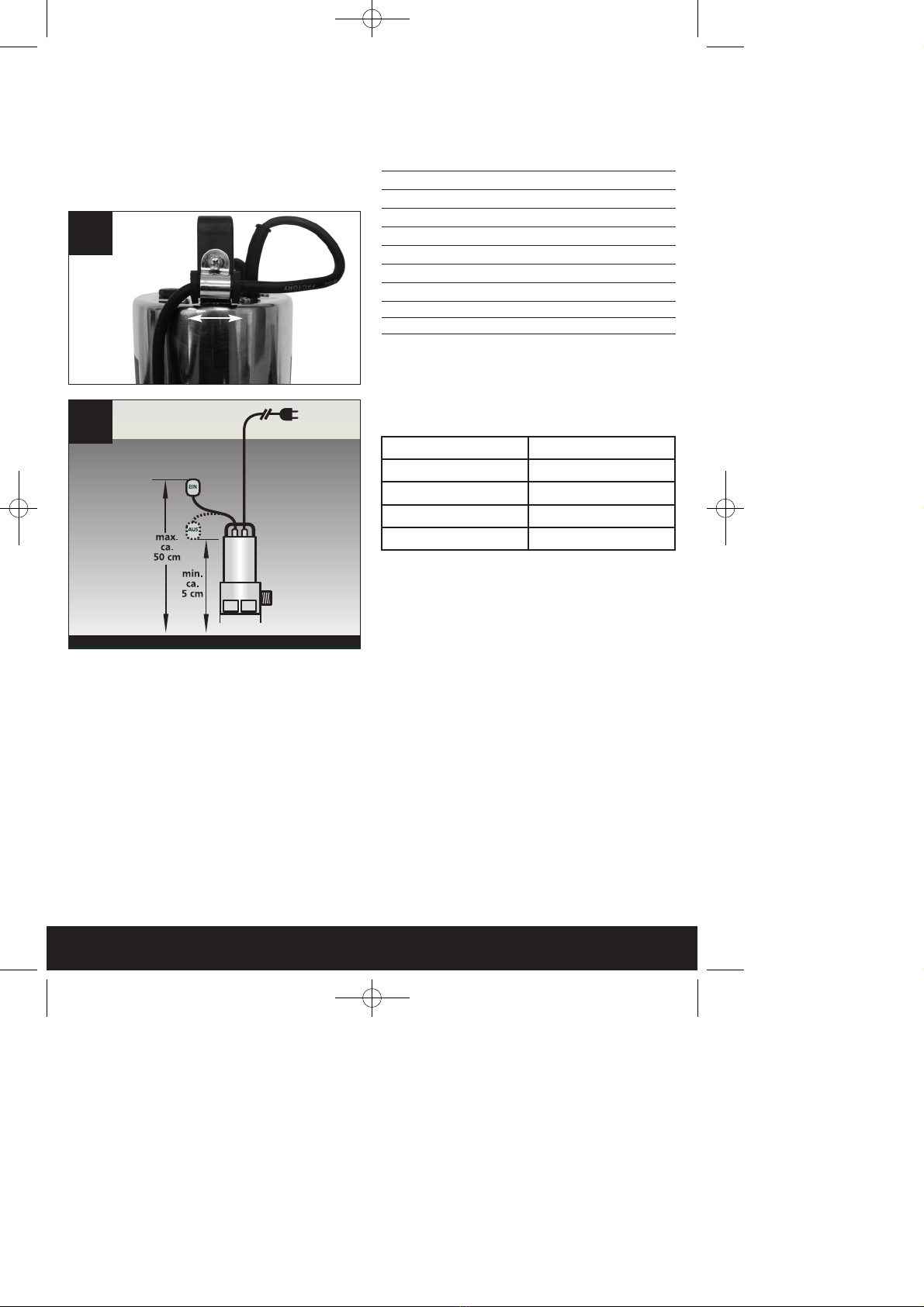
3. Installation (Fig. 2)
The pump is installed as follows:
●In a stationary position with fixed pipeline
or
●In a stationary position with a flexible hose pipe.
You should never install the pump by suspending it
unsupported from its delivery pipe or power cable.
The pump must be suspended from the specially
provided handle or be placed on the bottom of the
shaft. To guarantee that the pump works properly,
the bottom of the shaft must be kept free of sludge
and dirt of all kinds.
If the water level becomes too low, any sludge in the
shaft will dry out quickly and stop the pump from
starting up. It is necessary, therefore, to check the
submersible motor pump regularly (by carrying out
start-up tests).
The float is adjusted in a way that the pump can
immediately be started
The pump shaft should have minimum dimensions of
40 x 40 x 50 cm, so that the floating switch can move
freely.
2
Anleitung GLSP 1002_SPK7:Anleitung GLSP 1002_SPK7 27.06.2008 11:25 Uhr Seite 4

After Sales Support TEL: 1300 130 579 WEB: www.rossmac.com
5
4. Mains supply
Your new pump is equipped with a shock-proof plug
according to regulations. The pump is designed to be
connected to a 240 V ~ 50 Hz safety socket.
Make sure that the socket is sufficiently secured
(min. 6 Amp.) and is in excellent condition. Introduce
the plug into the socket and the pump is ready to go.
Important Note!
If the mains cable or plug suffers any damage from
external action, repairs to the cable are prohibited.
5. Areas of use
This pump is used primarily as a cellar pump. When
installed in a shaft, this pump provides protection
from flooding.
They are also used wherever water has to be moved
from one place to another, e.g. in the home,
agriculture, horticulture, plumbing and many other
applications.
This pump is not for commercial use.
Your pump is designated for the circulation of water
with a maximum temperature of 35° C.
This pump may not be used for other fluids,
especially motor fuels, cleaning fluids, and other
chemical products!
6. Setting to work
After having read these instructions carefully, you
can set your pump to work, reconsidering the
following items:
●Check if the pump rests on the ground of the
shaft.
●Check if pressure cord has been attached
properly .
●Check if electrical connection is 240 V ~ 50 Hz.
●Check if socket is in good condition.
●Make sure that water and humidity can never
come to the mains supply.
●Avoid pump running dry.
7. Maintenance guidelines
This pump is an approved, maintenance-free high
quality product, which is subject to severe final
controls.
We recommend, regular inspection and maintenance
to ensure long equipment life and uninterrupted
operation.
Important! Note!
●Remove the mains plug before all maintenance
work.
●In the event that the pump is often transported in
the course of operation, it should be
cleaned out with clear water after every use.
●In case of stationary installation, the function of
the floating switch should be checked every 3
months.
●All fibrous particles which may have built-up inside
the pump housing should be removed with a water
jet.
●Every 3 months the shaft ground and walls should
be cleaned from mud.
●Remove deposits on the floater with clear water.
Cleaning the impeller
If excessive deposits collect in the pump case, you
must dismantle the bottom part of the pump as
follows:
1. Undo the 4 screws from the bottom of the intake
cage.
2. Remove the intake cage from the pump case.
3. Clean the impeller with clear water.
Important! Do not put down or rest the pump on
the impeller!
4. Assemble in reverse order
3
Anleitung GLSP 1002_SPK7:Anleitung GLSP 1002_SPK7 27.06.2008 11:25 Uhr Seite 5

After Sales Support TEL: 1300 130 579 WEB: www.rossmac.com
6
8. Setting the ON/OFF switching point
(Fig. 4+5)
The ON/OFF switching point can be infinitely
adjusted with the height adjustment facility.
Before you put the pump into operation, please check
the following:
●The float switch must be installed so that the level
of the ON operating point and the level of the OFF
operating point can be reached easily and with
little force. To check this, place the pump in a
vessel filled with water, raise the float switch
carefully by hand and then lower it again. As you
do so, note whether the pump switches on and off.
●Make sure that the distance between the float
switch head and the latching holder is not too
small. Proper operation is not guaranteed if the
gap is too small.
●When you set the float switch, make sure that it
does not touch the base before the pump switches
off. Caution! Risk of running dry.
9. Technical Data
Power supply 240V ~ 50Hz
Power consumption 1,000 Watt
Delivery rate max.. 20.000 L/h
Delivery height max 8 m
Immersion depth max. 5 m
Water temperature max. 35°C
Hose connection 1 1/2“ threaded end
Foreign bodies up to dia. 20 mm
Switching point height: ON max. approx. 50 cm
Switching point height: OFF min. approx. 5 cm
10. Performance data
11. Disposal and recycling
The unit and its accessories are made of various
types of material, such as metal and plastic.
Defective components must be disposed of as
special waste. Ask your dealer or your local council.
12. Ordering replacement parts
Please quote the following data when ordering
replacement parts:
앬Type of machine
앬Article number of the machine
앬Identification number of the machine
앬Replacement part number of the part required
4
5
Delivery head Delivery rate
2 m max.: 18,200 l/h
4 m max.: 14,800 l/h
6 m max.: 10,400 l/h
8 m max.: 7,170 l/h
Anleitung GLSP 1002_SPK7:Anleitung GLSP 1002_SPK7 27.06.2008 11:25 Uhr Seite 6

After Sales Support TEL: 1300 130 579 WEB: www.rossmac.com
7
13. Troubleshooting
Problem
Pump does not start
No flow
Pump does not switch off
Insufficient flow
Pump switches off after short
operating period
Causes
– No mains supply
– Float switch does not activate
pump
– Inlet sieve is clogged
– Pressure hose is bent
– Float cannot sink down
– Inlet sieve is clogged
– Reduced pumping capacity by
dirty and abrasive water
– Thermal cutout stops pump
due to dirty water
– Water too hot. Thermal-cutout
stops pump
Solutions
– Check mains supply
– Adjust float to a higher
position
– Clean inlet sieve water jet
– Reset hose
– Place pump properly on shaft
ground
– Clean inlet sieve
– Clean pump and replace
worn-out parts
– Remove mains plug. Clean
pump and shaft
– Make sure that a water
temperature of max. 35°C is
not exceeded
Anleitung GLSP 1002_SPK7:Anleitung GLSP 1002_SPK7 27.06.2008 11:25 Uhr Seite 7

After Sales Support TEL: 1300 130 579 WEB: www.rossmac.com
EH 06/2008 (01)
The reprinting or reproduction by any other means, in whole or in part,
of documentation and papers accompanying products is permitted only
with the express consent of ISC GmbH. Technical changes subject to change
Never place any electric tools in your household refuse.
Seek advice on correct disposal from local waste authorities.
Anleitung GLSP 1002_SPK7:Anleitung GLSP 1002_SPK7 27.06.2008 11:25 Uhr Seite 8
This manual suits for next models
1
Table of contents
Other Gardenline Water Pump manuals
Popular Water Pump manuals by other brands

Graco
Graco E-Flo EC1140 Instructions-parts list

Crane
Crane BARNES SITHE 3SCM Installation and operation manual

Ebsray
Ebsray E Series Installation, operation & maintenance instructions

Oase
Oase NEPTUN 600 operating instructions

Central Machinery
Central Machinery CENTRAL MACHINERY 92274 Assembly and operating instructions

Unitec
Unitec 10942 instruction manual

Tallas Pumps
Tallas Pumps P1 330W Instruction for installation and maintenance

Flowserve
Flowserve 6LR-18A manual

Crane
Crane BARNES EH HT Series Installation and operation manual

DP
DP DPHM Installation and operating instructions

Lowara
Lowara DOMO Quick start up guide

Graco
Graco 222-832 Instructions-parts list