HYDRAULIC VARIABLE DISPLACEMENT PUMP
INSTALLATION GUIDE
Dynaset
O
y
|
Menotie
3,
FI-33470
Y
löjär
vi,
Finland
|
tel:
+358
3
3488
200
|
[email protected] |
ww
w
.dynaset.com
6
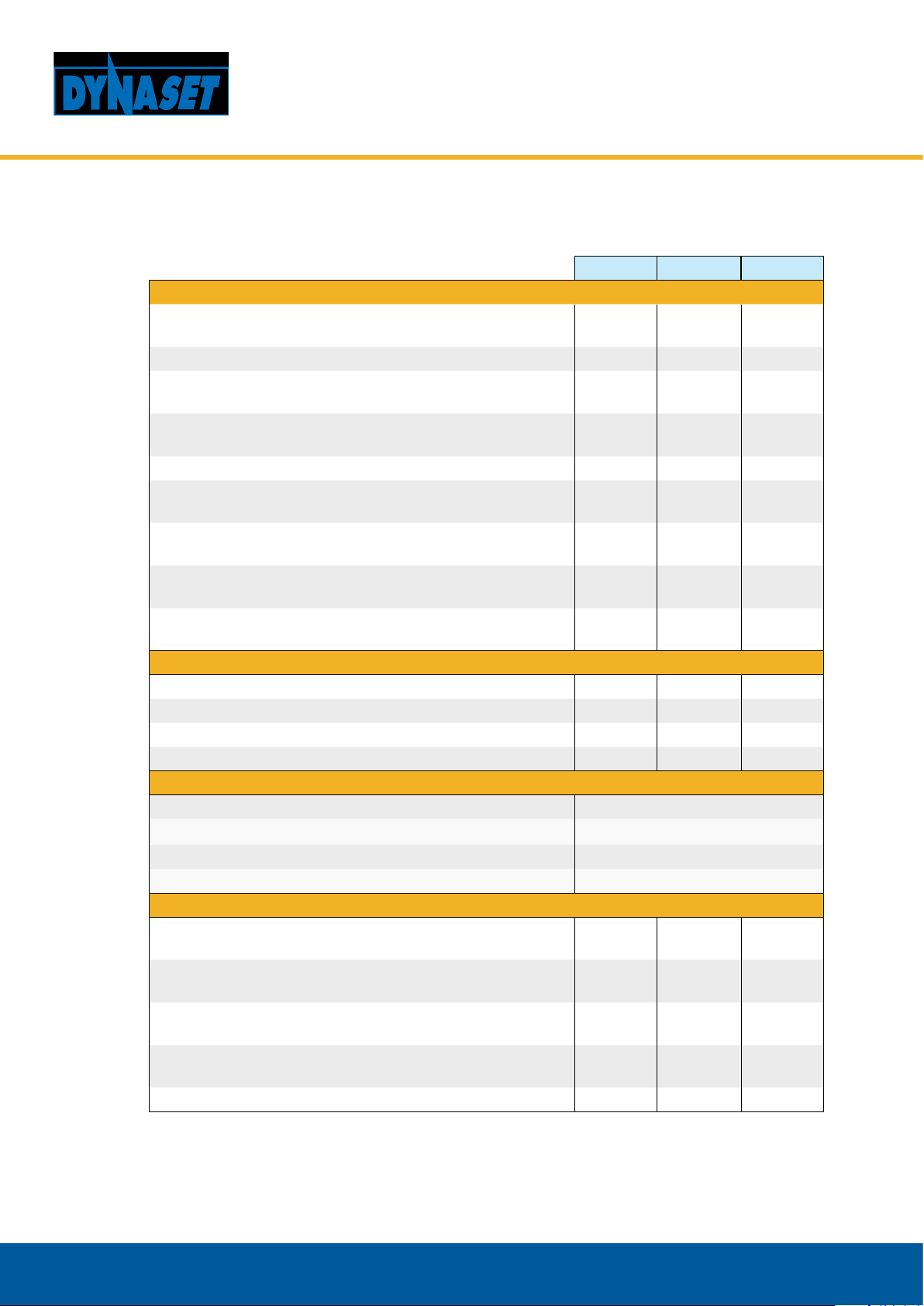
4. INSTALLATION MEASUREMENTS
60 90 110
Flange DIN ISO 7653 DIN ISO 7653 DIN ISO 7653
Axle DIN ISO 14 B8x32x35 DIN ISO 14 B8x32x35 DIN ISO 14 B8x32x35
amm (in) 50 (1.97) 50 (1.97) 50 (1.97)
bmm (in) 25 (0.98) 28 (1.10) 27,5 (1.08)
cmm (in) 32 (1.26) 32 (1.26) 32 (1.26)
dmm (in) 18 (0.71) 18 (0.71) 18 (0.71)
emm (in) 55 (2.17) 55 (2.17) 54,85 (2.16)
fmm (in) 9 (0.35) 9 (0.35) 9 (0.35)
gmm (in) 15 (0.59) 15 (0.59) 15 (0.59)
hmm (in) 100 (3.94) 106 (4.17) 112 (4.41)
imm (in) 253,5 (9.94) 277.5(10.93) 279,5 (13.07)
jmm (in) 95,25 (3.75) 95,25 (3.75) 45,1 (1.77)
kmm (in) 91,25 (3.59) 94 (3,7) 91 (3,58)
lmm (in) 86 (3.39) 89,5 (3.52) 95 (3.74)
mmm (in) 98,5 (3.88) 106 (4.17) 111 (4.37)
nmm (in) 102 (4.02) 101 (3.98) 106 (4.17)
omm (in) 80 (3.15) 80 (3.15) 80 (3.15)
pmm (in) 98,5 (3.88) 106 (4.17) 111 (4.37)
qmm (in) 115 (4.53) 120 (4.72) 127 (5.00)
r Ømm 80 -0,03
-0,06 80 -0,03
-0,08 80 -0,03
-0,08
s - M8 M8 M8
t Ømm (in) 13 (0.5) 13 (0.5) 13 (0.5)
umm(in) 65 - 109 (2.56 - 4.29)*
vmm(in) 38mm(1 1/2"), 42 mm, 50mm(2"), 64mm(2 1/2"), 76(3")*
*Dierent ange size options available depending on the required ow rate.
Measurements may vary if pump is equipped with additional options, suchs as valves or different flanges.