manuals.online logo
Brands
  1. Home
  2. •
  3. Brands
  4. •
  5. Samoa
  6. •
  7. Water Pump
  8. •
  9. Samoa 340120 Operating manual

Samoa 340120 Operating manual

1
R. 06/20 834 808
SAMOA Industrial, S.A. · Pol. Ind. Porceyo, I-14 · Camino del Fontán, 831 · 33392 - Gijón - Spain · Tel.: +34 985 381 488 · www.samoaindustrial.com
2020_06_18-09:00
3:1 RATIO AIR OPERATED HIGH VOLUME OIL PUMPS PUMPMASTER 4
BOMBAS NEUMÁTICAS DE ACEITE PUMPMASTER 4, RATIO 3:1
DRUCKLUFTBETRIEBENE ÖLPUMPE PUMPMASTER 4 ÜBERSETZUNG 3:1
PROPULSORA PNEUMÁTICA PARA ÓLEO LUBRIFICANTE PUMPMASTER 4, RATEIO 3:1
ПНЕВМАТИЧЕСКИЕ МАСЛЯНЫЕ НАСОСЫ PUMPMASTER 4 ДЛЯ ТЯЖЕЛЫХ УСЛОВИЙ,
КОЭФФИЦИЕНТ СЖАТИЯ 3:1
Parts and technical service guide
Guía de servicio técnico y recambio
Bedienungsanleitung und Teileliste
Manual de Serviços Técnicos e Reposições
Руководство по техническому обслуживанию и деталям
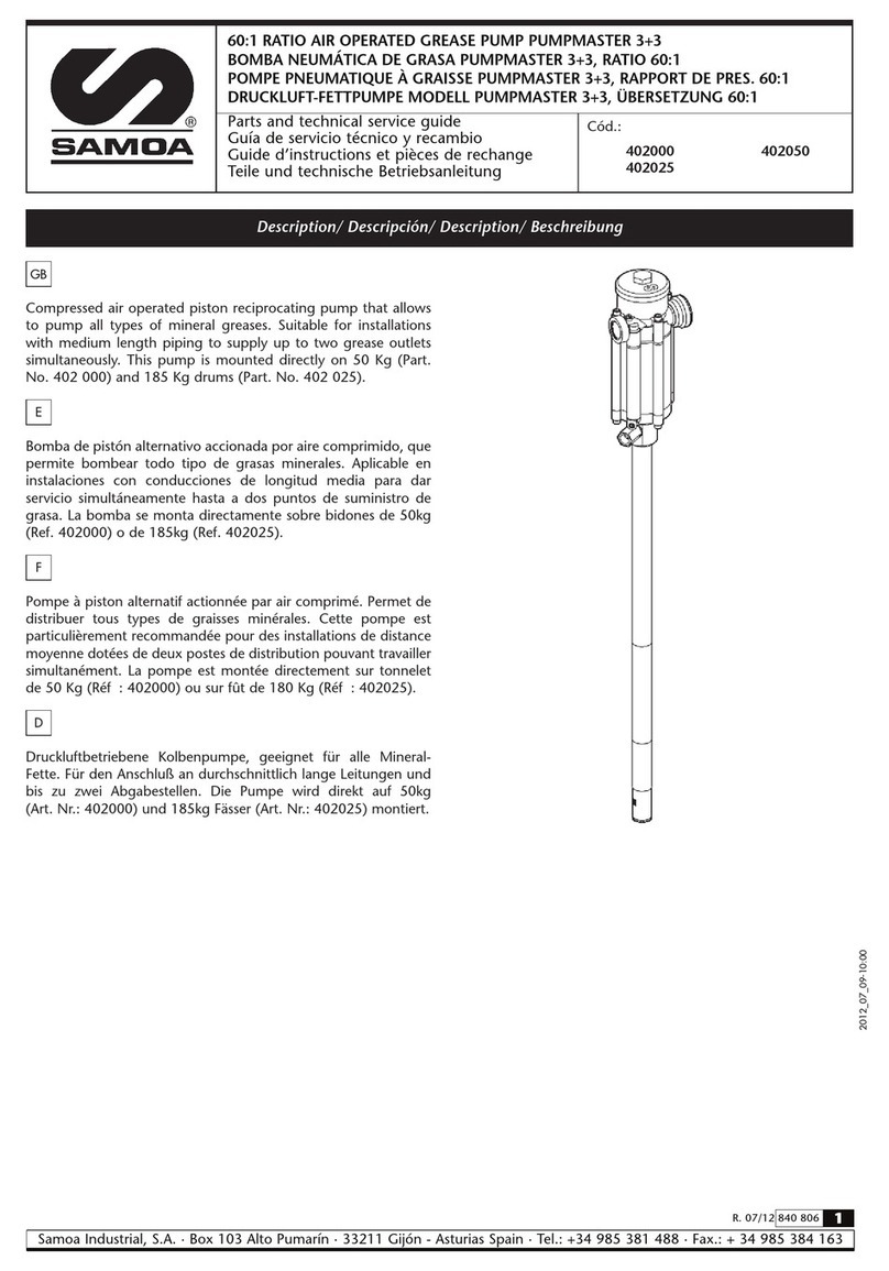
Description / Descripción / Beschreibung / Descrição da Bomba / Описание
Compressed air operated piston reciprocating medium pressure
pumps. Suitable for the transfer of heavy viscosity oil and
distribution of oil through pipe works, hose reels and meters.
High output allows simultaneous operation when used with
multi outlet systems. These pumps can be supplied as separate
components or as complete systems with all the elements
necessary for its installation. These pumps may be mounted on
drums, tanks or wall, using the appropriate accessories.
EN
Bombas de pistón alternativo accionadas por aire comprimido
de media presión para transvasar aceites viscosos o distribución
de aceite a través de conducciones, incluso suministrando fluido
en varias salidas provistas de enrolladores y contadores. Las
bombas pueden ser suministradas como componentes separados
o en forma de sistemas completos con todos los elementos
precisos para su instalación. Han sido concebidas para montaje
sobre bidón, cisterna o mural, utilizando los accesorios de
aspiración de fluido apropiados.
ES
Part No. / Cód. / Art. Nr. / Cód. /
Номер по каталогу:
340120 341120
Fig. 1
Die PumpMaster 4 DP 3:1 plus ist eine doppelwirkende
Druckluftkolbenpumpe zur Förderung von hochviskosen Ölen in
stationären bzw. fahrbaren Einheiten sowie in Anlagen mit
Rohrsystem und mehreren Abgabestellen, die gleichzeitig im
Einsatz sind.
Die Pumpen sind geeignet für Fass-, Wand- oder
Fahrwagenmontage.
Die Pumpen können einzeln als Komponenten oder als komplettes
System mit allem für die Montage notwendigem Zubehör
geliefert werden.
DE
Propulsora de pistão alterativo acionada por ar comprimido de
média pressão para transferência óleo lubrificante de alta
viscosidade e abastecimento de óleo de condutores, inclusive o
abastecimento em vários pontos providos de carreteis e
medidores. As propulsoras podem ser usadas com acessórios
opcionais ou em forma de sistemas completos com todos os
acessórios necessários para cada utilização. São adaptáveis a
unidades móveis, recipientes, tambores, reservatórios ou parede,
sendo utilizados os equipamentos de sucção apropriados para
cada tipo de aplicação.
Поршневые насосы среднего давления возвратно-поступательного
действия с приводом сжатым воздухом. Предназначены для
перекачки высоковязких масел и раздачи масла через трубопроводы,
катушки со шлангами и счетчики. Высокая производительность
позволяет использовать насос для обслуживания нескольких
одновременно работающих точек раздачи. Насосы этого типа могут
поставляться в виде отдельных компонентов или комплектных
систем со всеми необходимыми для установки элементами. При
помощи соответствующих принадлежностей насосы могут
устанавливаться на бочках, баках или стенах.
PT RU
Рис. 1
2834 808 R. 06/20
SAMOA Industrial, S.A. · Pol. Ind. Porceyo, I-14 · Camino del Fontán, 831 · 33392 - Gijón - Spain · Tel.: +34 985 381 488 · www.samoaindustrial.com
2020_06_18-09:00
Installation / Instalación / Montage / Instalaçåo / Монтаж
Die Pumpe kann direkt auf dem Faß oder auf der Wandkonsole
befestigt werden (Bild 2).
• Dazu die Sternschraube (836150) lösen, die untere Mutter
(736152) herausziehen und in der 2"-Öffnung am Fass oder
der Wandhalterung verschrauben.
• Sternschraube (836150) und Klemmstück (836400) am
Saugrohr positionieren.
• Danach die Pumpe durch die Öffnung am Fass oder der
Halterung einführen und mit der Sternschraube in der
gewünschten Höhe befestigen.
Насосы этого типа могут устанавливаться непосредственно
на бочки, баки или в настенный кронштейн с соединительным
отверстием 2” (рис. 2).
• Ослабить звёздчатую гайку (836150) переходника, чтобы
снять расположенную ниже гайку (736152), и вкрутить
переходник в отверстие 2” в бочке или кронштейне.
• Установить звёздчатую гайку (836150) и внутреннюю
деталь (836400) на всасывающую трубу.
• Вставить насос в отверстие и закрепить на требуемой
высоте, затянув звёздчатую гайку.
DE
RU
836150
836400
736152
Fig. 2
These pumps can be mounted directly on drums, tanks, or on a
wall bracket fitted with a 2" bung (fig. 2).
• Loose the star nut (836150) of the bung adaptor to remove
the inferior nut (736152), and screw this into the 2" bung
opening of the drum or bracket.
• Place the star nut (836150) and the ring (836400) on the
suction tube.
• Introduce the pump through the opening and fasten the
assemble at the desired height by tightening the star nut.
EN ES
Las bombas pueden ser montadas directamente sobre
bidones, cisternas o sobre un soporte mural que dispongan
de rosca 2" BSP H (fig. 2).
• Afloje la tuerca en estrella (836150) del adaptador para extraer la
parte inferior del mismo (736152) y rósquela en el brocal de 2"
del bidón o del soporte.
• Coloque la tuerca en estrella (836150) y el anillo (836400) del
adaptador en el tubo.
• Introduzca la bomba por el brocal y apriete el conjunto a la
altura deseada.
PT
A propulsora é adaptável a tambores com capacidade para
200 l, podem ser adaptadas à parede, usando o suporte de
parede apropriado (figura 2). Possuem adaptadores 2” BSP,
que se encaixam perfeitamente ao orifício do tambor ou do
suporte (figura 2).
Para instalar a propulsora:
• Afrouxar a porca em formato de estrela (836150) ddo adaptador
para retirar a parte inferior (736152) e Rosquear no bocal do
tambor ou rosca 2" do suporte de parede a parte roscado do
adaptador.
• Colocar a porca estrela (836150) e a parte inferior do
adaptador (836400) no tubo de sucção da propulsora.
• Introduzir a bomba no bocal do tambor ou suporte de parede
e apertar o conjunto do adaptador com a propulsora na altura
desejada.
Рис. 2
3
R. 06/20 834 808
SAMOA Industrial, S.A. · Pol. Ind. Porceyo, I-14 · Camino del Fontán, 831 · 33392 - Gijón - Spain · Tel.: +34 985 381 488 · www.samoaindustrial.com
2020_06_18-09:00
See figure 3 for a typical installation with all the recommended
accessories for the pump to operate correctly.
NOTE: The compressed air supply must be between 40 – 140 psi
(3 and 10 bar), being 90 psi (6 bar) recommended pressure. An
air closing valve must be installed, in order to be able to close
the compressed air line at the end of the day (If the air inlet not
is closed and there is a leakage in some point of the oil outlet
circuit, the pump will start automatically, emptying the
container).
EN ES
A título informativo, se muestra en la figura 3 una instalación
típica con todos los elementos recomendados para su correcto
funcionamiento.
NOTA: La presión de alimentación de aire debe estar comprendida
entre 3 y 10 bar (40 y 140 psi) siendo 6 bar (90 psi) la presión
recomendada. Es aconsejable instalar, asimismo, una válvula de
cierre para poder cerrar la alimentación de aire al final de la
jornada. (En caso de roturas o fugas en la salida de aceite, si la
alimentación de aire no está cerrada, la bomba se pondría en
marcha automáticamente, pudiendo vaciarse completamente el
depósito).
Bild 3 zeigt den Anschluss mit allen empfohlenen Teilen, die für
eine einwandfreie Funktion erforderlich sind.
ACHTUNG: der Luftdruck muss zwischen 3 und 10 bar (40 und
140 psi) betragen, ideal ist ein Druck von 6 bar (90 psi). Es ist
ratsam, ein Absperrventil einzubauen, damit die Luftzufuhr
jederzeit abgestellt werden kann, insbesondere bei Arbeitsschluss.
(Ist die Luftzufuhr nicht geschlossen, kann es bei einem Leck im
Öl-kreislauf um automatischen Start der Pumpe und zur völligen
Entleerung der Tank kommen).
DE
RU
Para titulo informativo, como mostra a figura 3, ilustramos uma
instalação típica com todos os elementos recomendados para o
correto funcionamento da propulsora.
NOTA: A pressão de alimentação de ar deve estar calibrada
entre 3 e 10 bar (40 a 140 psi), sendo 3-10 bar (40-140 psi) a
pressão recomendada é de 80 psi. Mesmo assim é recomendado
instalar o filtro regulador de ar, para poder regular e fechar a
alimentação de ar no final de cada dia de trabalho (no caso de
rupturas ou vazamentos na saída do óleo, se a alimentação de ar
não estiver fechada, a bomba se coloca em funcionamento
automaticamente, podendo esvaziar completamente o deposito
de óleo).
PT
Fig. 3
На рис. 3 показан пример стандартной установки насоса со всеми
рекомендованными принадлежностями. Данная установка
гарантирует правильную работу насоса.
ПРИМЕЧАНИЕ: Давление подачи сжатого воздуха должна быть в пределах от 3 до 10 бар (40 - 140 фунтов/кв. дюйм), рекомендуемое
давление - 6 бар (90 фунтов/кв. дюйм).
Следует установить отсечной воздушный клапан для перекрытия линии подачи сжатого воздуха в конце рабочей смены. (Если впуск воздуха
не закрыт и есть утечка в какой-либо точке контура выпуска масла, насос автоматически запускается, опорожняя ёмкость с маслом).
Typical installation / Conexión tipo de la bomba / Installationsbeispiel / Tipos de conexões para instalação /
Стандартная установка
Рис. 3
4834 808 R. 06/20
SAMOA Industrial, S.A. · Pol. Ind. Porceyo, I-14 · Camino del Fontán, 831 · 33392 - Gijón - Spain · Tel.: +34 985 381 488 · www.samoaindustrial.com
2020_06_18-09:00
Pos. Description Descripción Beschreibung Part No. / Cód. / Art. Nr.
AAir closing valve Válvula de cierre de aire Luftventil 950319
BFilter Regulator Filtro Regulador Druckregler/Filter 241501
CAir hose Manguera de aire Luftschlauch 247710
DQuick coupling Enchufe rápido Luftkupplung 253138
EConnection nipple Conector rápido Liftnippel 259038
F3:1 Pump PM4 (stubby) Bomba PM4 3:1 (corta) 3:1 Pumpe PM4 (Kurz) 340120
GPressure relieve valve Válvula de descarga Überdruckventil 609007
HOil hose Manguera de aceite Ölschlauch 362301
IOil closing valve Válvula de cierre de aceite Kugelhahn 950303
JBung adaptor Adaptador deslizante Fassverschraubung 360002
KWall bracket Soporte mural Wandhalter 360102
LSuction attachment Conjunto de succión Saugeinheit 367000
EN ES DE
Operation / Modo de empleo / Inbetriebnahme / Modo de operação da propulsora / Эксплуатация
This pump is self–priming. To prime it the first time, you must
connect the air supply to the pump and slowly increase the air
pressure from 0 to the desired pressure using a pressure
regulator, while keeping the outlet valve (ex. an oil control gun)
opened. Once oil starts to come out through the oil gun / guns,
the pump is primed.
NOTE: It is important that the foot valve does not get in contact
with dirty areas, such as a workshop floor, because it may enter
dirt or foreign particles that can damage the seals.
EN ES
Esta bomba es auto-cebante. Para cebarla la primera vez, es
conveniente conectar el aire a la bomba incrementando la presión
lentamente desde 0 bar a la presión deseada con el regulador de
presión, manteniendo la válvula de salida (ej. una pistola de
aceite) abierta. Cuando el aceite empieza salir de la pistola / las
pistolas, la bomba está cebada.
NOTA: Es importante que la válvula de pie no esté en contacto
con zonas sucias, tales como el suelo de un taller, porque puede
entrar virutas o partículas que podrían llegar a dañar las juntas.
Die Pumpe ist selbstansaugend. Zum ersten Starten die
Luftzufuhr anschliessen und den Druck mit Hilfe des Mano-
meters langsam von 0 auf den benötigten Druck erhöhen. Dabei
soll der Ölauslauf geöffnet sein (z. B. die Auslauf-pistole
geöffnet). Sobald Öl austritt, ist die Pumpe einsatzbereit.
ACHTUNG: Es ist sehr wichtig darauf zu achten, dass das
Fussventil der Pumpe nicht in Kontakt mit Schmutz bzw.
Schmutzpartikeln kommt. Dies könnte zu ernsthaften
Beschädigungen an den Dichtungen führen.
DE
RU
Pos. / Поз Descrição Наименование Cód. / Номер детали.
AA Registro para fechamento da linha de ar Отсечной воздушный клапан 950319
BFiltro Regulador de Ar Воздушный фильтр + регулятор 241501
CMangueira Воздушный шланг 247710
DEngate Rapido Быстроразъемная муфта 253138
EConector para engate rápido Пневматический ниппель 259038
FPropulsora PM4 3:1 (corta) Насос PM4 (короткий), коэффициент сжатия 3:1 340120
GVálvula de alivio Разгрузочный клапан давления 609007
HMangueira para abastecimento Шланг для масла 362301
IVálvula de abastecimento Шаровой кран 950303
JAdaptador para tambor Переходник для крышки насоса 360002
KSuporte de parede Настенный кронштейн 360102
LMangote para sucção Узел для перекачки масла 367000
PT RU
Esta bomba é auto-ferrante. Para a primeira vez, é conveniente
ligar o ar à bomba aumentando lentamente a pressão de 0 bar até
à pressão desejada com o regulador de pressão, mantendo a
válvula de saída (por exemplo, uma pistola de óleo) aberta.
Quando o óleo começa a sair da pistola, a bomba é escorvada.
NOTA: É importante que a válvula de pé da propulsora não esteja
em contato com áreas que contenham sujeira, como o chão de
oficinas, porque partículas da sujeira podem ser aspiradas juntamente
com o óleo danificando as juntas e outros mecanismos da propulsora.
PT
Typical installation / Conexión tipo de la bomba / Installationsbeispiel / Tipos de conexões para instalação /
Стандартная установка
Это насос самозаливающегося типа. Для первой заливки
необходимо подсоединить подачу воздуха к насосу и с
помощью регулятора давления постепенно увеличивать
давление воздуха от 0 до требуемой величины, сохраняя
при этом выпускной клапан (например, на масляном шприце)
открытым. Заливка насоса будет закончена, когда масло
начнет выходить из шприца или шприцев.
ПРИМЕЧАНИЕ: Важно, чтобы в нижний клапан не
попадала грязь или инородные частицы с пола, поскольку
это может привести к загрязнению клапана и повреждению
уплотнений.
5
R. 06/20 834 808
SAMOA Industrial, S.A. · Pol. Ind. Porceyo, I-14 · Camino del Fontán, 831 · 33392 - Gijón - Spain · Tel.: +34 985 381 488 · www.samoaindustrial.com
2020_06_18-09:00
Repair and cleaning procedure / Procedimientos de reparación y limpieza /
Reparatur- und Reinigungsanleitung / Procedimentos de reparo e limpeza / Ремонт и очистка
Separate the air motor from the pump / Como separar el motor de aire de la bomba / Trennen von Luftmotor und
Pumpe / Como separar o motor de ar da bomba / Отсоединение пневматического двигателя от насоса
WARNING: Before starting any kind of maintenance or repair,
disconnect the compressed air supply and open a downstream
valve to relieve the oil pressure.
ATENCIÓN: Antes de empezar cualquier tipo de mantenimiento
o reparación, desconecte el aire de alimentación y accione la
válvula de salida para soltar la presión del aceite.
EN ES
Achtung: Vor Beginn jeglicher Arbeiten am Gerät die Luftzufuhr
abschalten und das Auslaufventil öffnen, um den Öldruck
abzubauen.
DE
1. Attach the pump to a vice in horizontal position, grabbing it
by the pump body.
2. To unscrew the suction tube (735204-S/735303-) from the
pump body, use a 40 mm wrench on the hexagon of the
foot valve body (42) (fig. 4). Pull first clockwise to break the
sealing, and then counter clockwise to loosen and remove
the tube assembly.
3. Remove the pin (29) situated in the upper part of the
connecting rod (30) (fig. 5) and unscrew the rod from the air
piston (10).
EN ES
1. Fije la bomba en una mordaza agarrando por el cuerpo de la
bomba con la bomba en posición horizontal.
2. Para desenroscar el tubo de aspiración (735204-S/735303-L)
del cuerpo de la bomba, use llave fija de 40 mm en el cuerpo
válvula de pie (42) (fig. 4). Tire primero contra las agujas del
reloj para romper el sellador y luego hacia el otro sentido para
desenroscar y quite el conjunto tubo de aspiración.
3. Extraiga el pasador (29) situado en la parte superior del eje
válvula impulsión (30) (fig. 5) y desenrosque el eje del
vástago (10).
1. Die Pumpe waagerecht auf einer Werkbank in den
Schraubstock spannen und am Pumpkörper fixieren.
2. Zum Abschrauben des Saugrohres (735204-S/735303) vom
Pumpenkörper zuerst das Rohr lösen (gegen den
Uhrzeigersinn) und danach komplett unter leichtem Drehen
(im Uhrzeigersinn) herausziehen.
Dazu mit einem 40-mm Schrauben-schlüssel in den Kerben
am Fussventil-Körper (42) ansetzen. (Bild 4).
3. Den Stift (29) im unteren Teil der Verbindungsstange (30)
entfernen (Bild 5) und von der Luftkolbenstange (10) lösen.
DE
RU
Fig. 4 Fig. 5
ATENÇÃO: Antes de começar qualquer tipo de manutenção,
desconectar o engate rápido da propulsora e acionar o bico de
abastecimento para eliminar a pressão do óleo.
ВНИМАНИЕ: Перед началом любого технического обслуживания или ремонта отключить подачу сжатого воздуха и открыть
клапан на выходе для сброса давления масла.
PT
RU
1. Fixar bomba em uma morsa, prendendo o corpo da
propulsora na posição horizontal.
2. Para desrosquear o tubo de sucção (735204-S/735303) do
corpo da propulsora, usar uma chave fixa de 40 mm no
corpo da válvula de pé (42) (figura 4). Primeiro puxar o tubo
para baixo para retirar o selamento entre o tubo e o corpo,
depois girar no sentido horário para desrosquear e retirar o
tubo de sucção.
3. Retirar o passador elástico (29) localizado na parte superior
do eixo da válvula de impulsão (30) (figura 5) e desrosquear
o eixo do pistão (10).
PT
1. Закрепить насос в тисках в горизонтальном положении и зажать так, чтобы губки тисков уперлись в зажимные
площадки на корпусе насоса.
2. Чтобы выкрутить всасывающую трубу (28) из корпуса насоса, установить 40-миллиметровый гаечный ключ на
шестигранник корпуса нижнего клапана (43-44) (рис. 4). Повернуть сначала по часовой стрелке, чтобы разорвать
уплотнение, затем против часовой стрелки для ослабления и снятия трубы.
3. Извлечь штифт (29), расположенный в верхней части соединительного штока (30) (рис. 5), и отвинтить шток от
пневматического поршня (10).
Рис. 4 Рис. 5
6834 808 R. 06/20
SAMOA Industrial, S.A. · Pol. Ind. Porceyo, I-14 · Camino del Fontán, 831 · 33392 - Gijón - Spain · Tel.: +34 985 381 488 · www.samoaindustrial.com
2020_06_18-09:00
Repair and cleaning procedure / Procedimientos de reparación y limpieza /
Reparatur- und Reinigungsanleitung / Procedimentos de reparo e limpeza / Ремонт и очистка
Foot valve / Válvula de pie / Fussventil / Válvula de Pé / Обратный клапан
1. Attach the suction tube assembly to the vice and unscrew
the foot valve body (42) from the suction tube.
2. Unscrew the nut (43) and clean the washer (40) and the valve
body (42), replace in case of damage. Assemble the pump
following the previous instructions, reversing each step.
EN ES
DE
1. Fije el conjunto tubo de succión en la mordaza y desenrosque
el cuerpo válvula de pie (42) del tubo de succión.
2. Desenrosque la tuerca (43) y limpie la arandela (40) y el
cuerpo válvula (42), en caso de deterioro sustitúyalos. Vuelva
a montar en orden inverso.
1. Das komplette Saugrohr in den Schraubstock spannen und
das Fussventil (42) vom Saugrohr abschrauben.
2. Mutter (43) lösen und Scheibe (40) und Fussventil (42)
reinigen, falls beschädigt erzetzen. Gemäss dieser Anleitung
den Zusammenbau Schritt für Schritt in umgekehrter
Reihenfolge durchführen.
39
40
41
42
43
Fig. 6
29
30
31
32
33
34
35
36
37
38 Fig. 7
Impulsion valve / Válvula de impulsión / Oberes Ventil / Válvula superior / Верхний клапан
1. Unscrew the valve seat (38) from the valve body (32) and
remove the washer (35), the oil plunger (34), the washer
(33), the ball (37) and the spring (36).
2. Clean these parts carefully. In case of damage, replace the
affected parts.
3. Assemble the pump following the previous instructions,
reversing each step.
EN
ES
DE
1. Desenrosque el asiento válvula (38) del cuerpo válvula (32) y
quite la arandela (35), el collarín (34), la arandela (33), la
bola (37) y el muelle (36).
2. Limpie estas piezas cuidadosamente. En caso de deterioro,
sustituya los elementos afectados.
3. Vuelva a montar en orden inverso.
1. Den Ventilsitz (38) vom Ventilkörper (32) abschrauben und
die Unterlegscheibe (35), den Öl-Kolben (34), den Ring (33),
die Kugel (37) und die Feder (36) entfernen.
2. Diese Teile sorgfältig säubern. Beschädigte Teile ersetzen.
3. Gemäss dieser Anleitung den Zusammenbau Schritt für
Schritt in umgekehrter Reihenfolge durchführen. Dichtung
für das Gewinde am Ventilsitz (38) verwenden.
PT RU
1. Fixar o tubo de sucção na morsa e desrosquear o corpo da
válvula de pé (42) do tubo de sucção.
2. Desrosquear a porca (43) e limpar a arruela (40) e o corpo da
válvula (42).
3. Voltar a montar na ordem contraria dos passos acima.
1. Осторожно установить узел всасывающей трубы в тиски
и отвинтить корпус нижнего клапана (42) от трубы.
2. Открутить гайку (43) и очистить шайбу (40) и корпус
клапана (42). Заменить в случае повреждения. Собрать
насос следуя вышеописанным инструкциям в обратной
последовательности.
Рис. 6
Рис. 7
7
R. 06/20 834 808
SAMOA Industrial, S.A. · Pol. Ind. Porceyo, I-14 · Camino del Fontán, 831 · 33392 - Gijón - Spain · Tel.: +34 985 381 488 · www.samoaindustrial.com
2020_06_18-09:00
PT
1. Fixar o tubo de sucção na morsa e desrosquear o corpo da
válvula de pé (42) do tubo de sucção.
2. Desrosquear a porca (43) e limpar a arruela (40) e o corpo
da válvula (42).
3. Voltar a montar na ordem contraria dos passos acima.
Repair and cleaning procedure / Procedimientos de reparación y limpieza /
Reparatur- und Reinigungsanleitung / Procedimentos de reparo e limpeza / Ремонт и очистка
Packing set / Conjunto empaquetadura / Dichtung / Conjunto das vedações / Установка уплотнений
1. Follow the procedure for the air motor until the air piston
(10) is outside the air motor body.
2. Remove the circlip (22) and the packing set (21) from the air
motor body. Replace in case of damage.
3. Assemble the pump following the previous instructions,
reversing each step.
NOTE: The packing set is directional and must be mounted with
the seals positioned as shown in fig. 12.
EN ES
DE
1. Siga el procedimiento del motor de aire hasta haber extraído
el vástago (10) del cuerpo motor.
2. Quite el anillo de seguridad (22) y el conjunto empaquetadura
(21) del cuerpo motor de aire. Sustituya en caso de deterioro.
3. Vuelva a montar en orden inverso.
NOTA: El conjunto empaquetadura debe ser montada con las
juntas según fig. 12.
1. Den Anweisungen zur Zerlegung des Luftmotors folgen, bis
der Kolben (10) ausserhalb des Luftmotors ist.
2. Den Sprengring (22) und den Dichtungssatz (21) vom
Luftmotor-Körper lösen. Beschädigte Teile ersetzen (Bild 11).
3. Der Zusammenbau erfolgt gem. dieser Anweisungen Schritt
für Schritt in umgekehrter Reihenfolge.
ACHTUNG: Beim Einbau des Dichtungssatzes muss die richtige
Reihenfolge eingehalten werden. Dies wird in Bild 12 gezeigt.
21
22
Fig. 11
Fig. 12
RU
1. Отвинтить седло клапана (38) от корпуса клапана (32) и
снять шайбу (35), маслосъемное кольцо (34), шайбу (33),
шар (37) и пружину (36).
2. Тщательно очистить эти детали. При необходимости
заменить поврежденные детали.
3. Произвести сборку насоса, следуя вышеописанным
инструкциям в обратной последовательности.
PT
RU
1. Seguir os procimentos de manutenção do motor de ar até
ter retirado o pistão (10) do corpo do motor.
2. Retirar o anel de segurança (22) e o conjunto de vedação
(21) do corpo do motor de ar.
Substituir as peças se danificadas.
3. Voltar a montar a valvula usando os passos acima na ordem
contraria.
NOTA: o conjunto de vedação (21) deve ser montado com as
vedações segundo a figura 12.
1. Выполнять процедуру, описанную для пневмодвигателя,
пока пневматический поршень (10) не выйдет из корпуса
двигателя.
2. Снять стопорное кольцо (22) и комплект уплотнений (21)
(рис. 10) с корпуса пневмодвигателя. Заменить в случае
повреждения.
3. Произвести сборку насоса, следуя вышеописанным
инструкциям в обратной последовательности.
ПРИМЕЧАНИЕ: Комплект уплотнений устанавливается
в строго определенном положении. См. положение
уплотнений при установке на рис. 12.
Impulsion valve / Válvula de impulsión / Oberes Ventil / Válvula superior / Верхний клапан
Рис. 11
Рис. 12
8834 808 R. 06/20
SAMOA Industrial, S.A. · Pol. Ind. Porceyo, I-14 · Camino del Fontán, 831 · 33392 - Gijón - Spain · Tel.: +34 985 381 488 · www.samoaindustrial.com
2020_06_18-09:00
3
4
Fig. 8
10
10
19
940333
Repair and cleaning procedure / Procedimientos de reparación y limpieza /
Reparatur- und Reinigungsanleitung / Procedimentos de reparo e limpeza / Ремонт и очистка
1. Fix the air motor body in a suitable way and unscrew the air
motor screw (940333) then remove it slowly.
2. Check the upper spring (3) and the spring stop (4) inside the
air motor dolly (1). Replace in case of damage.
3. Dismount the lower o-ring (20) and muffler (19) and pull up
the inverting set until the hole in pump piston (10) gets
visible in the opening where the muffler was dismounted.
Introduce a steel rod (8 mm) in the hole to lock the piston.
4. Use a prepared 17mm wrench (see fig. 9) to disassemble the
inverting set (5).
5. Remove the piston (10) and disassemble the circlip (11), the
washer (12) and the seal (13) (fig. 10). Check the piston for
scratches and replace damaged parts.
6. Assemble the pump following the previous instructions,
reversing each step.
EN
Inverting set and air motor / Conjunto inversor y motor de aire /
Umkehrschalter und Luftmotor / Conjunto do inversor de ar / Реверсивный механизм и пневмомотор
ES
1. Afloje los tornillos 940333 y extraiga la cazoleta tirando
lentamente hacia arriba.
2. Verifique el muelle superior (3) y el tope muelle (4) en la
cazoleta. Sustituya en caso de deterioro.
3. Desmonte la junta tórica inferior (20) y el silenciador (19)
y tire del conjunto inversor hacia arriba hasta que el
agujero en el vástago (10) quede visible en la apertura
donde el silenciador fue quitado. Introduzca una varilla
acerada (8 mm) en el agujero del pistón para bloquear el
mismo.
4. Desenrosque el conjunto inversor (5) con una llave fija de
17 mm preparada (fig. 9).
5. Quite el vástago (10) y desmonte el anillo de seguridad (11),
la arandela (12) y el collarín (13) (fig. 10). Verifique que el
vástago no esté rayado y sustituya piezas deterioradas.
6. Vuelva a montar en orden contrario.
Рис. 8
9
R. 06/20 834 808
SAMOA Industrial, S.A. · Pol. Ind. Porceyo, I-14 · Camino del Fontán, 831 · 33392 - Gijón - Spain · Tel.: +34 985 381 488 · www.samoaindustrial.com
2020_06_18-09:00
Repair and cleaning procedure / Procedimientos de reparación y limpieza /
Reparatur- und Reinigungsanleitung / Procedimentos de reparo e limpeza / Ремонт и очистка
1. Den Luftmotor sichern um den Deckel (Schrauben 940333)
zu entfernen.
2. Die obere Feder (3) und die Federhalterung (4) innerhalb des
Deckels überprüfen. Falls beschädigt, ersetzen.
3. Die untere O-Ring (20) und den Dämpfer (19) entfernen und
den Umkehrschalter soweit herausziehen, bis die Öffnung im
Pumpkolben (10) sichtbar wird, aus der der Dämpfer
entfernt wurde. Eine 8 mm Stahlstange in dieses Loch
einführen, um den Kolben zu blockieren.
4. Mit einem vorbereiteten 17 mm-Schraubenschlüssel (Bild 9),
wird der Umkehrschalter (5) abgeschraubt.
5. Den Kolben (10) entfernen und den Sprengring (11), die
Beilagscheibe (12) und die Dichtung (13) zerlegen (Bild 10)
Kolben auf Kratzer prüfen. Evtl. beschädigte Teile ersetzen.
6. Gemäss dieser Anleitung den Zusammenbau Schritt für
Schritt in umgekehrter Reihenfolge durchführen.
1. Надлежащим образом закрепить корпус пневматического
двигателя, открутить и осторожно извлечь винт
пневмодвигателя (940333).
2. Проверить верхнюю пружину (3) и пружинный упор (4)
внутри крышки пневмодвигателя (1). Заменить в случае
повреждения.
3. Снять нижнее стопорное кольцо (20), глушитель (19) и
продвинуть реверсивный переключатель так, чтобы в
том месте, где был установлен глушитель, показалось
отверстие в поршне насоса (10). Вставить стальной
стержень (8 мм) в отверстие, чтобы зафиксировать
поршень.
4. С помощью заранее подготовленного 17-миллиметрового
гаечного ключа (см. рис. 9) открутить реверсивный
механизм (5).
5. Снять поршень (10), затем стопорное кольцо (11), шайбу
(12) и уплотнение (13) (рис. 10). Проверить поршень на
наличие царапин и заменить поврежденные детали.
6. Произвести сборку насоса, следуя вышеописанным
инструкциям в обратной последовательности.
DE
RU
5
10
11
12
13
Fig. 9
Fig. 10
1. Afrouxar os parafusos e retirar a tampa superior, puxando
para cima.
2. Verificar a mola superior (3) e o assento da mola (4) na
tampa. Substituir estas peças se necessario.
3. Desmontar o anel de segurança inferior (20) e o silenciador
(19), tirar o conjunto do inversor puxando para cima até
que o orificio do pistão (10) estija visivel, para que o
conjunto do silenciador seja desmontado. Introduzir uma
vareta de aço (8 mm) no orificio para retirar o pistão.
4. Usar uma chave fixa 17 mm (figura 9) para separar o cojunto
do inversor (5).
5. Remover o pistão (10) e desmontar o anel elastico (11), a
vedação (12) e o retentor (13) (figura 10). Analisar o pistão
e substituir as peças que estiverem danificadas.
6. Montar o conjunto do inversor no sentido contrario aos
passos acima.
PT
Inverting set and air motor / Conjunto inversor y motor de aire /
Umkehrschalter und Luftmotor / Conjunto do inversor de ar / Реверсивный механизм и пневмомотор
Рис. 9
Рис. 10
10 834 808 R. 06/20
SAMOA Industrial, S.A. · Pol. Ind. Porceyo, I-14 · Camino del Fontán, 831 · 33392 - Gijón - Spain · Tel.: +34 985 381 488 · www.samoaindustrial.com
2020_06_18-09:00
Troubleshooting / Anomalías y sus soluciones / Probleme und deren Lösungen /
Problemas e Soluções / Поиск и устранение неисправностей
EN
ES
Symptoms Possible Reasons Solutions
The pump is not working or there is
no oil delivery.
Not enough air supply pressure. Increase the air supply pressure.
Some outlet line component is clogged or
closed. Clean or open the outlet circuit.
The pump begins to operate very fast. The drum/tank is empty or the oil level is
beneath the suction tube inlet.
Replace the drum/fill the tank or lower the
suction tube until the inlet reaches the oil
level.
The pump keeps on operating
although the oil outlet is closed.
There is an oil leakage in some point of the
outlet circuit. Verify and tighten or repair.
Impurities in the upper valve or in the foot
valve (fig. 6-7). Dismount and clean. Replace in case of
damage.
Oil leakage through the air outlet
muffler. Oil has by-passed to the air motor caused
by worn or damaged packing set (21). Replace the packing set (21).
Air leakage through the air outlet
muffler.
The piston seal (13) is worn or damaged. Dismount and clean. Replace in case of
damage.
The air motor dolly is scratched. Replace air motor dolly.
The air piston rod (10) is scratched. Replace the piston rod (10).
The reversing set (5) is worn or damaged. Replace the reversing set (5).
Diminution of the oil delivery. Impurities in the upper valve or in the foot
valve (fig. 6-7). Dismount and clean. Replace in case of
damage.
The pump operates one cycle and
stops. The top reversing spring (3) is damaged. Replace the top reversing spring (3).
Síntomas Posibles causas Soluciones
La bomba no funciona o no hay
entrega de aceite. Presión de suministro de aire no adecuada. Incremente la presión de suministro de aire.
Algún elemento del circuito de salida está
obstruido o cerrado. Limpie o abra el circuito de salida.
La bomba empieza a bombear
mucho más deprisa. El bidón esta vacío o el nivel de la aceite
esta por debajo de la entrada de la bomba. Sustituya el bidón o cale el tubo de succión
hasta llegar al nivel del aceite.
La bomba sigue funcionando aunque
se cierre la salida de aceite. Existe fuga de aceite en algún punto del
circuito de salida. Verifique y apriete o repare.
Suciedad en la válvula superior o en la
válvula de pie (fig. 6-7). Desmonte y limpie las válvulas. En caso de
deterioro, sustitúyalas.
Perdida de aceite por el silenciador
del escape de aire. Ha pasado aceite al motor de aire causado
por deterioro del conjunto empaquetadura
(21).
Sustituya el conjunto empaquetadura (21).
Perdida de aire por el silenciador del
escape de aire. El collarín del vástago (13) está deteriorado. Sustituya el collarín del vástago.
La cazoleta del motor de aire está rayada. Sustituya la cazoleta.
El vástago (10) está rayado. Sustituya el vástago (10).
El conjunto inversor (5) está desgastado. Sustituya el conjunto inversor (5).
Disminución de caudal entrega de
aceite. Suciedad en la válvula superior o en la
válvula de pie (fig. 6-7). Desmonte y limpie las válvulas. En caso de
deterioro, sustitúyalas.
La bomba empieza a funcionar, pero
para después de un ciclo. Rotura del muelle inversor superior (3). Sustituya el muelle inversor superior (3).
11
R. 06/20 834 808
SAMOA Industrial, S.A. · Pol. Ind. Porceyo, I-14 · Camino del Fontán, 831 · 33392 - Gijón - Spain · Tel.: +34 985 381 488 · www.samoaindustrial.com
2020_06_18-09:00
DE
Troubleshooting / Anomalías y sus soluciones / Probleme und deren Lösungen /
Problemas e Soluções / Поиск и устранение неисправностей
Symptome mögl. Ursache Lösungen
Die Pumpe fördert nicht oder es
kommt kein Öl.
Zu wenig Druck. Druck erhöhen.
Eine Auslaufleitung ist verstopft oder
geschlossen. Auslauf öffnen oder reinigen.
Die Pumpe beginnt sehr schnell zu
arbeiten. Das Fass ist leer oder der Ölpegel liegt unter
der Ansaugöffnung. Fass wechseln oder Saugrohr tiefer setzen.
Die Pumpe arbeitet weiter, obwohl
der Ölauslauf geschlossen ist.
Ölleitung undicht. Prüfen, Anschlüsse nachziehen, defekte Teile
auswechseln.
Schmutz am oberen Ventil oder am
Fussventil. Entfernen, reinigen, defekte Teile ersetzen.
Ölverlust am Schalldämpfer. Öl gelangt in den Luftmotor, weil die
Dichtungen abgenutzt oder defekt sind. Dichtungssatz ersetzen. (21)
Luftverlust am Schalldämpfer.
Die Kolbendichtung (13) ist abgenutzt oder
beschädigt. Entfernen, reinigen, defekte Teile ersetzen.
Der Luftmotor-Deckel ist verkratzt. Ersetzen.
Die Kolbenstange (10) ist zerkratzt. Ersetzen.
Das Rückschlagventil (5) ist abgenutzt oder
defekt. Ersetzen.
Verminderte Ölzufuhr. Schmutz am oberen Ventil oder am
Fussventil. Zerlegen und reinigen, ggf. ersetzen.
Die Pumpe arbeitet nur einen
Arbeitsgang. Die obere Feder im Rückschlagventil (3) ist
beschädigt. Ersetzen.
PT
Problema Causas Possíveis Solução
A propulsora não funciona ou o
abastecimento de óleo não esta
acontecendo.
Pressão de ar não está adequada. Aumentar a pressão de ar.
Algum elemento na linha de saída está
obstruído ou fechado.
Verificar os elementos da linha de
abastecimento (mangueira e válvulas
de óleo).
Die Pumpe beginnt sehr schnell zu
arbeiten.
O tambor ou reservatório esta vazio ou o
nível de óleo esta abaixo da válvula de pé
da propulsora.
Substituir o tambor de óleo ou encher
o reservatório até o nível do óleo alcançar a
válvula da propulsora, ou toda a
capacidade.
A propulsora continua funcionando
quando a válvula de saída esta
desativada.
Há vazamento em algum ponto na linha de
saída.
Verificar as conexões da mangueira, a
válvula de controle de óleo e fazer a
manutenção ou a substituição caso
estejam com problema.
Sujeira na válvula superior ou na válvula de pé. Desmontar e limpar as válvulas, ou
substitui-las em caso de estarem danificadas.
Vazamento de óleo através do
silenciador de ar. O óleo esta passando através da motor de
ar, causou danos no conjunto de vedação. Substituir o conjunto de vedação (21).
Vazamento de ar pelo silenciador.
O retentor do pistão (13) esta danificado. Substituir o pistão.
A carcaça do motor de ar esta danificada. Substituir a carcaça.
O pistão está deteriorado. Substituir o pistão.
O conjunto do inversor (5) esta desgastado. Substituir o conjunto do inversor.
Diminuição da vazão no
abastecimento de óleo. Sujeira na válvula superior ou na
válvula de pé. Desmontar e limpar as válvulas.
Substitui-las no caso de estarem danificadas.
A propulsora para de funcionar após
um ciclo de trabalho. Ruptura na mola do inversor superior (3). Substituir a mola do inversor superior.
12 834 808 R. 06/20
SAMOA Industrial, S.A. · Pol. Ind. Porceyo, I-14 · Camino del Fontán, 831 · 33392 - Gijón - Spain · Tel.: +34 985 381 488 · www.samoaindustrial.com
2020_06_18-09:00
Dimensions / Dimensiones / Abressungen / Dimensões / Размеры
EN ES DE
B
A
C
D
3/8"
3/4"
1/4"
3/4"
Model / Modelo /
Modell / Modelo /
Модель A (mm) B (mm) C (mm) D (mm) Weight / Peso /
Gewicht / Peso / Вес
340 120 585 385 52 200 5,7 kg
341 120 1295 385 52 910 7,7 kg
PT RU
(* for 340120 only)
(* solo para la bomba 340120)
(* nur für 340120)
(* solo pa propulsora 340120)
(* только для 340120)
Troubleshooting / Anomalías y sus soluciones / Probleme und deren Lösungen /
Problemas e Soluções / Поиск и устранение неисправностей
Симптом Возможные причины Способ устранения
Насос не работает или
нет подачи масла.
Недостаточное давление подачи воздуха. Увеличить давление подачи воздуха.
Какой-либо компонент выпускной линии засорен или закрыт. Очистить или открыть выходной контур.
Насос начинает работать
очень быстро.
В бочке или ёмкости отсутствует масло или
поверхность масла находится ниже уровня входного
отверстия всасывающей трубы.
Поставить новую бочку с маслом/заполнить ёмкость
или опустить всасывающую трубу так, чтобы входное
отверстие находилось ниже уровня масла.
Насос продолжает
работать, хотя выход
масла закрыт.
Утечка масла в какой-либо точке выходного контура. Проверить и затянуть соединения, или
отремонтировать.
Загрязнение в верхнем или нижнем клапане (рис. 6-7). Разобрать и очистить клапан. Заменить клапан в
случае повреждения.
Утечка масла через
глушитель шума выпуска
воздуха.
Попадание масла в пневматический двигатель
вследствие износа или повреждения уплотнительного
комплекта (21).
Заменить уплотнительный комплект.
Утечка воздуха через
глушитель шума выпуска.
Износ или повреждение уплотнения поршня (13). Разобрать и очистить. Заменить в случае
повреждения.
Повреждение крышки пневматического двигателя. Заменить крышку пневматического двигателя.
Повреждение поршня насоса (10). Заменить шток поршня.
Износ или повреждение узла реверсирования (5). Заменить узел реверсирования.
Уменьшение подачи
масла. Загрязнение в верхнем или нижнем клапане (рис. 6-7). Разобрать и очистить клапан. Заменить клапан в
случае повреждения.
Ход пневматического
поршня. Повреждение верхней возвратной пружины (3). Заменить верхнюю возвратную пружину.
RU
13
R. 06/20 834 808
SAMOA Industrial, S.A. · Pol. Ind. Porceyo, I-14 · Camino del Fontán, 831 · 33392 - Gijón - Spain · Tel.: +34 985 381 488 · www.samoaindustrial.com
2020_06_18-09:00
Technical data / Datos técnicos / Technische Daten / Características Técnicas / Технические данны
EN ES DE
Maximum Air pressure Presión de aire máxima Max. Luftdruck 10 bar (140 psi)
Minimum air pressure Presión de aire mínima Min. Luftdruck 3 bar (40 psi)
Maximum delivery Caudal máximo Max. Förderleistung 42 l/min
Air inlet thread Rosca entrada aire Luftanschluss 3/8" (H) / (F)
Oil outlet thread Rosca salida aceite Druckseite 3/4" (H) / (F)
Air piston diameter Diámetro pistón de aire Luftmotor 88 mm (3,5")
Air piston stroke Recorrido del pistón de aire Kolbenhub 75 mm (3")
Pressão máxima de ar Максимальное давление воздуха 10 bar (140 psi) / 10 бар (140 фунтов/кв.дюйм)
Pressão mínima de ar Минимальное давление воздуха 3 bar (40 psi) / 3 бар (40 фунтов/кв.дюйм)
Vazão máxima Максимальная производительность 42 l/min / 42 л/мин
Conexão de entrada de ar Соединение на входе воздуха 3/8" (H) / (F)
Conexão de saída do óleo Соединение на выходе масла 3/4" (H) / (F)
Diâmetro do motor de ar Диаметр пневматического поршня 88 mm (3,5")
Curso do pistão ar Ход пневматического поршня 75 mm (3")
PT RU
Ex. Ej. Beispiel Ej. Характеристика
Air pressure Presión de aire Eingangsdruck Pressão de ar Давление воздуха 6 bar (6 бар)
Backpressure Presión de salida Ausgangsdruck Pressão de saída Противодавление 11 bar (11 бар)
Outlet flow Salida de fluido Abgabe Saída do fluido Скорость потока 20 l/min (20 л/мин)
Air consuption Consumo de aire Luftverbrauch Consumo de ar Потребление воздуха 400 l/min (400 л/мин)
Cycles/min Ciclos/min Hub/min Ciclos/min Циклов/мин 215
SAE 30 - 23 ºC
l/min
0 50403010 20
012345678
0
25
20
15
10
5
0
50
150
100
250
200
300
350
9 10 11 12 13
Nl/min
SCFM
Nl/min
SCFM
5
10
15
10
15
18
20
5
Nl/min
SCFM
20
22
23
23,8
5
10
15
16
16,7
675
640
650
600
550
450
500
350
400
150
100
50
200
250
300
560
540
550
500
510
520
530
450
250
300
350
400
50
100
200
450
350
400
300
50
100
150
200
250
475
70 140 180 215 240 275 290260
6 bar - 90 psi
7 bar - 100 psi
5 bar - 70 psi
BAR
PSI
Gal / min 90 psi
6 bar
100 psi
7 bar
70 psi
5 bar
Cycles / minute - Ciclos/minuto -
Hub/min - Ciclos / minuto - цикл/мин
AIR CONSUMPTION / CONSUMO DE AIRE /
LUFTVERBRAUCH / CONSUMO DE AR / РАСХОД ВОЗДУХА
Fluid pressure
Presión del fluido
Pression du fluide
Mediendruck
Pressão fluido
Давление жидкости
90 фунтов/
кв.дюйм
6 бар
100 фунтов/
кв.дюйм
7 бар
70 фунтов/
кв.дюйм
5 бар
л/мин
гал/мин
бар
фунтов/
кв.дюйм
14 834 808 R. 06/20
SAMOA Industrial, S.A. · Pol. Ind. Porceyo, I-14 · Camino del Fontán, 831 · 33392 - Gijón - Spain · Tel.: +34 985 381 488 · www.samoaindustrial.com
2020_06_18-09:00
EN ES DE
PT
Repair kit/ Kit de reparación / Reparatursatz
Part No. / Cód. /
Art. Nr. Pos. Description Descripción Beschreibung
734953 1, 2, 2x(19), 2x(20), 2x(45) Muffler and filter kit Kit silencioso y filtros Schalldämpfer und Filter
Satz
734963 11, 12, 13, 14, 21, 22, 29,
31, 34, 41, 44 Air and oil packing kit Kit empaquetadura Luft– und Öl-Dichtungsatz
734955 3, 4, 5, 6, 7, 8, 9, 14 Motor repair kit Kit reparación Luftmotor Reparatursatz
734964 10, 14, 29, 44 Major repair kit
central bar Kit de reparación
vástago Reparatursatz Zentralteil
734957 16, 17 Discharge valve kit Kit válvula de descarga Abgabeventil
360001 23, 24, 25 Bung adaptor kit Kit adaptador Adapter-Kit
340 120
734965 29, 30-38 Piston Kit Kit pistón Kolbensatz
735205 39, 40, 41, 42, 43 Foot valve Válvula de pie Fussventil Satz
341 120
734966 29, 30-38 Piston Kit Kit pistón Kolbensatz
735304 39, 40, 42, 43 Foot valve Válvula de pie Fussventil Satz
RU
Reparo / Ремкомплект
Art. Nr. / Cód Pos. Descripción Описание
734953 1, 2, 2x(19), 2x(20), 2x(45) Conjunto silencioso e filtros Комплект для глушителя и
фильтра
734963 11, 12, 13, 14, 21, 22, 29,
31, 34, 41, 44 Conjunto de vedação Комплект пневматических и
масляных уплотнений
734955 3, 4, 5, 6, 7, 8, 9, 14 Conjunto de reparo Комплект для капитального
ремонта пневмодвигателя
734964 10, 14, 29, 44 Conjunto de reparo de retentor
do pistão Комплект для штока поршня
734957 16, 17 Válvula de alivio Комплект для переходника на
бочку
360001 23, 24, 25 Kit adaptador Комплект переходников
340 120
734965 29, 30-38 Conjunto do pistão Комплект для поршня
735205 39, 40, 41, 42, 43 Válvula de saída Комплект для нижнего клапана
341 120
734966 29, 30-38 Conjunto do pistão Комплект для поршня
735304 39, 40, 42, 43 Válvula de saída Комплект для нижнего клапана
Repair Kits and spare parts/ Kits de reparación y piezas de recambio / Ersatzteilliste /
Peças de Reposição / Список запасных частей
15
R. 06/20 834 808
SAMOA Industrial, S.A. · Pol. Ind. Porceyo, I-14 · Camino del Fontán, 831 · 33392 - Gijón - Spain · Tel.: +34 985 381 488 · www.samoaindustrial.com
2020_06_18-09:00
Repair Kits and spare parts/ Kits de reparación y piezas de recambio / Ersatzteilliste /
Peças de Reposição / Список запасных частей
45
Kit nº
360001
Kit nº
734957
17
Kit nº
№ комплекта
Kit nº
№ комплекта
Kit nº
№ комплекта
Kit nº
№ комплекта
Kit nº
№ комплекта
Kit nº
№ комплекта
Kit nº / № комплекта
Kit nº
№ комплекта
Kit nº
№ комплекта
Kit nº
№ комплекта
Kit nº
№ комплекта
16 834 808 R. 06/20
SAMOA Industrial, S.A. · Pol. Ind. Porceyo, I-14 · Camino del Fontán, 831 · 33392 - Gijón - Spain · Tel.: +34 985 381 488 · www.samoaindustrial.com
2020_06_18-09:00
For SAMOA INDUSTRIAL, S.A.
Por SAMOA INDUSTRIAL, S.A.
Für SAMOA INDUSTRIAL, S.A.
Por Samoa Industrial, S.A.
Pedro E. Prallong Álvarez
Production Director
Director de Producción
Diretor de Produção
Produktionsleiter
EC conformity declaration / Declaration CE de conformidad /
EG-Konformitätserklärung / Declaração de Conformidade
SAMOA INDUSTRIAL, S.A., Pol. Ind. Porceyo, I-14 · Camino
del Fontán, 831 · 33392 - Gijón - Spain, declares that this
product conforms with the EU Directive:
2006/42/EC
EN
SAMOA INDUSTRIAL, S.A.,Pol. Ind. Porceyo, I-14 · Camino
del Fontán, 831 · 33392 - Gijón - España, declara que este
producto cumple con la Directiva de la Unión Europea:
2006/42/CE
ES
SAMOA INDUSTRIAL, S.A.,Pol. Ind. Porceyo, I-14 · Camino
del Fontán, 831 · 33392 - Gijón - Spanien, bestätigt hiermit,
dass dieses Produkt der EG-Richtlinie(n):
2006/42/EG
entspricht.
DE
SAMOA INDUSTRIAL, S.A.,Pol. Ind. Porceyo, I-14 · Porceyo,
1-14. Caminho de Fontán, 831 * 33392 – Gijón – Espanha,
declara que os produtos 9043-P e 9043 cumprem as diretrizes
da União Europeia:
2006/42/EG
PT
Сертификат соответствия:
№ ТС RU C-ES.АБ58.В.01839, срок действия с 28.07.2017 по
27.07.2020, выдан органом по сертификации продукции «М-ФОНД»
ООО «Агентство по экспертизе и испытаниям продукции»; Адрес
125167, Россия, г. Москва, ул. Викторенко, дом 16, стр. 1. Телефон:
+74951501658, e-mail: [email protected]. Аттестат аккредитации
№RA.RU.11АБ58 от 07.04.2016 года.
Дата производства указана на маркировке изделия
Транспортировка
Изделие должно транспортироваться в заводской упаковке для
защиты от повреждений и влаги.
Хранение
Изделие должно храниться запакованным, в хорошо
проветриваемом и сухом помещении.
Утилизация
Выполняйте национальные правила утилизации и переработки
отслужившего оборудования, упаковки и принадлежностей.
RU

This manual suits for next models

1

Other Samoa Water Pump manuals

Samoa Larius SUPER NOVA 45:1 Operating instructions

Samoa

Samoa Larius SUPER NOVA 45:1 Operating instructions

Samoa LARIUS VEGA 5:1 Operating instructions

Samoa

Samoa LARIUS VEGA 5:1 Operating instructions

Samoa PM35 User manual

Samoa

Samoa PM35 User manual

Samoa PM100 Operating manual

Samoa

Samoa PM100 Operating manual

Samoa PM45 User manual

Samoa

Samoa PM45 User manual

Samoa LARIUS MIRO Operating instructions

Samoa

Samoa LARIUS MIRO Operating instructions

Samoa LARIUS GIOTTO User manual

Samoa

Samoa LARIUS GIOTTO User manual

Samoa 561610 Operating manual

Samoa

Samoa 561610 Operating manual

Samoa PUMPMASTER 3+3 Operating manual

Samoa

Samoa PUMPMASTER 3+3 Operating manual

Samoa 535810 Operating manual

Samoa

Samoa 535810 Operating manual

Samoa LARIUS MIRO Operating instructions

Samoa

Samoa LARIUS MIRO Operating instructions

Samoa PM35 Operating manual

Samoa

Samoa PM35 Operating manual

Samoa Larius P31 2:1 Operating instructions

Samoa

Samoa Larius P31 2:1 Operating instructions

Samoa NOVA 10:1 User manual

Samoa

Samoa NOVA 10:1 User manual

Samoa 402000 Operating manual

Samoa

Samoa 402000 Operating manual

Samoa 108000 Operating manual

Samoa

Samoa 108000 Operating manual

Samoa LARIUS GHIBLI 3:1 Operating instructions

Samoa

Samoa LARIUS GHIBLI 3:1 Operating instructions

Samoa Larius Zeus Series User manual

Samoa

Samoa Larius Zeus Series User manual

Samoa DC20 Series Operating manual

Samoa

Samoa DC20 Series Operating manual

Samoa Larius Vega 13:1 Operating instructions

Samoa

Samoa Larius Vega 13:1 Operating instructions

Samoa PUMPMASTER 6 Operating manual

Samoa

Samoa PUMPMASTER 6 Operating manual

Samoa 300 006 How to use

Samoa

Samoa 300 006 How to use

Samoa LARIUS SIRIO 32:1 Operating instructions

Samoa

Samoa LARIUS SIRIO 32:1 Operating instructions

Samoa 150 000 Operating manual

Samoa

Samoa 150 000 Operating manual

Popular Water Pump manuals by other brands

Warren rupp WR10 operating instructions

Warren rupp

Warren rupp WR10 operating instructions

Milton Roy MAXROY Series Actuator Capacity Control Manual

Milton Roy

Milton Roy MAXROY Series Actuator Capacity Control Manual

AL-KO TBP 6000/7 Original instructions for use

AL-KO

AL-KO TBP 6000/7 Original instructions for use

FPS IGP-A Series owner's manual

FPS

FPS IGP-A Series owner's manual

ARO 650888 Series Operator's manual

ARO

ARO 650888 Series Operator's manual

Husky 072-0030H Use and care guide

Husky

Husky 072-0030H Use and care guide

AMT 4895 Specifications information and repair parts manual

AMT

AMT 4895 Specifications information and repair parts manual

Secoh ATB WATER ATB-80 instruction manual

Secoh

Secoh ATB WATER ATB-80 instruction manual

Gormann-Rupp Pumps AMT 2820-98 Specifications information and repair parts manual

Gormann-Rupp Pumps

Gormann-Rupp Pumps AMT 2820-98 Specifications information and repair parts manual

STA-RITE 300E Series owner's manual

STA-RITE

STA-RITE 300E Series owner's manual

Graco Fire-Ball 205626 Instructions-parts list

Graco

Graco Fire-Ball 205626 Instructions-parts list

Pentair DKG instruction manual

Pentair

Pentair DKG instruction manual

BOC Edwards Seiko Seiki STP603 Series instruction manual

BOC Edwards

BOC Edwards Seiko Seiki STP603 Series instruction manual

KSB Amacan S 800-535 Installation & operating manual

KSB

KSB Amacan S 800-535 Installation & operating manual

Binks DX70 Service manual

Binks

Binks DX70 Service manual

CountyLine CL1800DC owner's manual

CountyLine

CountyLine CL1800DC owner's manual

Pentair JUNG PUMPEN US 62 instruction manual

Pentair

Pentair JUNG PUMPEN US 62 instruction manual

Flomotion Systems 4001V Series Installation and operation manual

Flomotion Systems

Flomotion Systems 4001V Series Installation and operation manual

manuals.online logo
manuals.online logoBrands
  • About & Mission
  • Contact us
  • Privacy Policy
  • Terms and Conditions

Copyright 2025 Manuals.Online. All Rights Reserved.